
Related Manuals for Studio Technologies 214


Summary of Contents for Studio Technologies 214
- Page 1 User Guide Issue 1, July 2014 This User Guide is applicable for serial numbers: M214-00151 and later Copyright © 2014 by Studio Technologies, Inc., all rights reserved www.studio-tech.com 50382-0714, Issue 1...
- Page 2 This page intentionally left blank.
-
Page 3: Table Of Contents
Installation ..............10 Configuration ..............13 Dante™ Configuration ........... 20 Operation ..............20 Technical Notes ............. 25 Specifications ..............30 Appendix A ..............31 Appendix B ..............32 Model 214 User Guide Issue 1, July 2014 Studio Technologies, Inc. Page 3... - Page 4 This page intentionally left blank. Issue 1, July 2014 Model 214 User Guide Page 4 Studio Technologies, Inc.
-
Page 5: Introduction
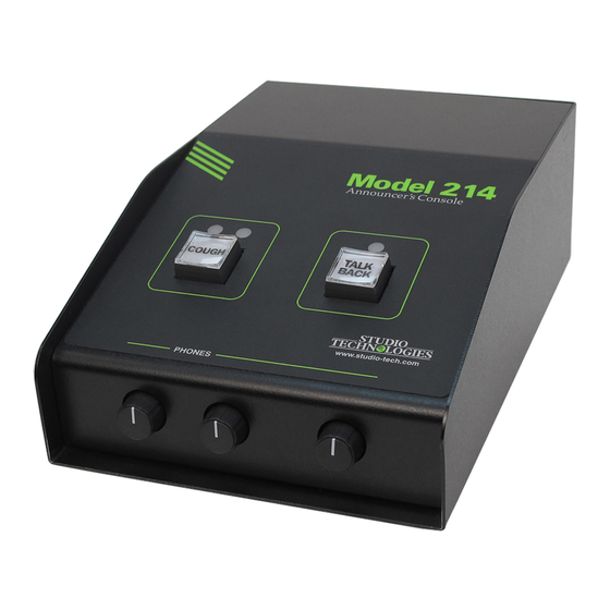
Two pushbutton switches allow the user to control the main and talkback audio output channels. Ease of use, configuration Figure 1. Model 214 front and back views flexibility, and sonic excellence are some of the unit’s highlights. System Features... - Page 6 Model active function for the main output. This 214 by way of a standard 3-pin female XLR mode would be appropriate for an appli- connector. cation such as stadium announcement. An alternate action “latching”...
- Page 7 These choices impact paragraph. The hybrid mode is especially which audio sources are utilized, how the useful when the Model 214 is used in a rotary level controls function, and what production-support application. sidetone action will take place. Four head- phone control configuration modes are of-...
- Page 8 “mix-minus” talent cue plication. This makes selecting the way signal is provided for the user. For appli- in which the Model 214 fits into an ap- cation flexibility the sidetone function can plication a simple matter. For example, be configured from among four choices,...
- Page 9 To support PoE power factory-supplied modules and interface management, the Model 214’s PoE inter- cable kits allows a Model 214 to be opti- face reports to the power sourcing equip- mized to meet the needs of specific ap- ment (PSE) that it’s a class 2 (low power)
-
Page 10: Installation
Model 214’s circuit board. Console Products Accessible using 3-pin “header” connec- The Model 214 is just one in a series of tors they allow specialized configurations Dante-enabled announcer console prod- to be created. Under software control, the ucts available from Studio Technologies. - Page 11 Microphone interconnection is made been much less. Enough said… by way of a 3-pin female XLR connec- tor which is located on the Model 214’s Headphone Output back panel. The mating connector (male) The Model 214’s headphone output is...
- Page 12 As a “head start” for some applications, volts, correct operation will take place over a clear sheet with a number of commonly a 10 to 18 volt range. The Model 214 re- used pushbutton designations printed on quires 270 milliamperes at 12 volts DC for it is included in the shipping carton.
-
Page 13: Configuration
fice supply stores. A pair of scissors or an X-ACTO (razor) knife will complete the task. Configuration For the Model 214 to support the needs of specific applications a number of operat- ing parameters must be configured. These include microphone preamplifier gain,... - Page 14 Small audio clicks or pops might occur Two pushbutton switches, located on the during gain transitions, but this shouldn’t bottom of the Model 214, are used to set be a major issue as long as associated the gain of the microphone preamplifier...
- Page 15 Model 214 its put connector, is provided as an aid when “smarts.” The software has been carefully using the Model 214. It can also be useful designed to provide a number of different when setting the gain of the Model 214’s ways in which the unit can function.
- Page 16 Low is appropriate will change state. Upon power up the when the Model 214 is to be used in an audio signal on the main output channel environment where the ambient light level will be in its muted state.
- Page 17 The balance (relative level) of both these signals is controlled by the rotary level control located in the center of the front panel. Sidetone audio is assigned to Model 214 User Guide Issue 1, July 2014 Studio Technologies, Inc. Page 17...
- Page 18 4 is controlled by the rotary level con- trol located on the right side of the front panel. The sidetone function will not be active. Figure 8. Headphone minimum level switch settings Issue 1, July 2014 Model 214 User Guide Page 18 Studio Technologies, Inc.
- Page 19 Model 214 unless they select it to do so Figure 10. System mode settings using the pushbutton switches. • When selected to the on-air mode, the...
-
Page 20: Dante Configuration
When selected for the correct applica- and two receive). tion, the production mode can prove to The Model 214 has a default Dante device be very useful. But it’s not appropriate name of ST-M214 and a unique suffix. The for on-air use! suffix identifies the specific Model 214... - Page 21 10 seconds after the unit begins Controller software application. Normal op- operation the display will stop lighting. This eration of the Model 214 can now begin. is a power saving measure. The display will again light after either or both of the push- Initial Operation buttons are pressed.
- Page 22 It will slowly light on and control the audio signals on the main and off green when the Model 214 is part of a talkback output channels. The way each Dante network and is serving as a clock operates depends on the selected configu-...
- Page 23 Main Output vis-à-vis talkback pushbutton. To clarify, when the Model 214 is set to either of the produc- Talkback Activity tion modes, the red LED will never light; This short section applies only in the case the green LED will light whenever micro- where the Model 214’s system mode is...
- Page 24 (50%) position of its rotation range. This is back output channel is normally muted. intended to serve as an aid to Model 214 The audio signal will become active users. In an ideal installation, setting the...
-
Page 25: Technical Notes
“XLR style” connectors. The spare con- Technical Notes nector locations are specifically included so that a Model 214 can be customized to meet the many specific needs that arise in Phantom Power broadcast and related audio applications. - Page 26 Switchcraft® 6-pin arrangement. Other headers, on 0.1-inch centers, are wired in connectors, such as the etherCON pro- parallel with some of the Model 214’s con- tected RJ45 and 3-conductor ¼-inch jack, nectors. This “no solder” solution makes can be also be installed. The 4-40 thread-...
- Page 27 “on-air” Most of the 3-position headers on the lights, and muting loudspeaker systems. Model 214’s main circuit board assembly To utilize the relay contacts does require are located close to their related input or the talents of a qualified technician. This output connectors.
- Page 28 12 volt DC source. a USB flash drive. The flash drive doesn’t have to be empty (blank) but must be in the 6. The Model 214 will run a “boot loader” personal-computer-standard FAT32 for- program that will immediately load the mat.
- Page 29 7. At this time the Model 214 is function- ing with the newly-loaded firmware and the USB flash drive can be removed. But to be conservative, remove power first and then remove the USB flash drive. 8. Apply power to the Model 214 and “read”...
-
Page 30: Specifications
USB: type A receptacle Network Interface: Spare Connector Locations: 2 Type: twisted-pair Ethernet, preferably with Power- Allows Studio Technologies’ cable assemblies or over-Ethernet (PoE) support option modules to be installed. Also compatible with Neutrik NC*D-L-1 connectors (*=3F, 3M, 5M, 6F, Data Rate: 100 Mb/s (10 Mb/s Ethernet not 6FS, etc.). - Page 31 Appendix A Attached to the bottom of the unit is a security panel with text that provides a summary of the configurable parameters and related information. Model 214 User Guide Issue 1, July 2014 Studio Technologies, Inc. Page 31...
- Page 32 Appendix B The following list provides details on the 3-pin header connectors located on the Model 214’s printed circuit board. Shown are both reference numbers and associated functions. P2: Microphone Input P10: Remote Switch Inputs Pin 1 common Pin 1 common...
Need help?
Do you have a question about the 214 and is the answer not in the manual?
Questions and answers