Table of Contents
Advertisement
Quick Links
Model 215A
Announcer's Console
User Guide
Issue Preliminary 1, October 2022
This User Guide is applicable for serial numbers
M215A-00151 and later with Main Firmware version 1.00 and later
and STcontroller software application version 3.08.00 and later
Copyright © 2022 by Studio Technologies, Inc., all rights reserved
studio-tech.com
50733-1022, Issue P1
Advertisement
Table of Contents

Related Manuals for Studio Technologies 215A


Summary of Contents for Studio Technologies 215A
- Page 1 This User Guide is applicable for serial numbers M215A-00151 and later with Main Firmware version 1.00 and later and STcontroller software application version 3.08.00 and later Copyright © 2022 by Studio Technologies, Inc., all rights reserved studio-tech.com 50733-1022, Issue P1...
- Page 2 This page intentionally left blank.
-
Page 3: Table Of Contents
Table of Contents Revision History ......................4 Introduction ........................ 5 Getting Started ......................9 Dante Configuration ....................10 Model 215A Configuration ..................12 Operation ........................17 Technical Notes ......................21 Specifications ......................25 Appendix A: STcontroller Default Configuration Values ..........27 Appendix B: 3-Pin Header Connector Details ............ -
Page 4: Revision History
Model 215A ANNOUNCER’S CONSOLE Revision History Issue Preliminary 1, October 2022: • Initial preliminary release. Issue Preliminary 1, October 2022 Model 215A User Guide Page 4 Studio Technologies, Inc. -
Page 5: Introduction
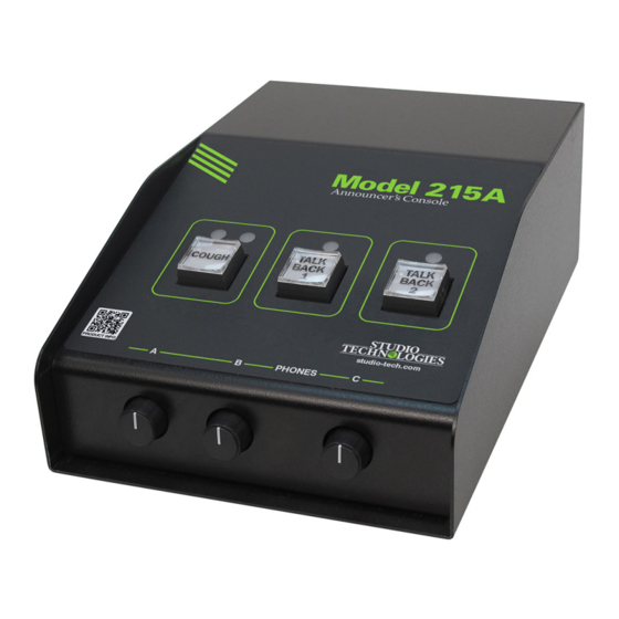
Output Channels and their Operation production personnel. A status LED is associated with each By way of the Dante interface, the Model 215A provides of the talkback pushbutton switches. The three pushbutton a main transmitter (output) channel and two talkback switches utilize gold-plated contacts for reliable long-term transmitter (output) channels. - Page 6 A large part of the Model 215A’s unique power is the ability in roles such as sports-event spotter, musical director, or to configure the operation of the main and talkback func- production assistant.
- Page 7 Rotary control B provides the same function for Dante receiver (input) channels 3 and 4. Audio data is sent to and from the Model 215A using the Rotary control C adjusts the sidetone level. Dante audio-over-Ethernet media networking technology.
- Page 8 Dante audio signal. of P48 phantom power can be enabled if required to support On its input side, the Model 215A allows up to four head- condenser microphones. The four Dante receiver (input) phone cue sources to be received from an audio console,...
-
Page 9: Getting Started
Updating As of the writing date of this guide, the Sennheiser HMD The Model 215A was designed so that in the future its 26-II and HMD 27 headsets are popular for on-air sports capabilities and performance can be easily enhanced. A broadcasting use. -
Page 10: Dante Configuration
12 volts, correct operation will finger-pressure only. No tool is required to replace the cap. take place over a range of 10 to 18 volts. The Model 215A’s If you need to make your own labels the process is quite operating current is modest (less than 300 milliamperes) simple. - Page 11 “console tape,” with its specific static IP address. mode will determine how the Dante receiver (input) chan- If knowledge of a Model 215A’s IP address has been mis- nels will be associated with the three level controls and the placed there is no reset button or other method to easily headphone output channels.
-
Page 12: Model 215A Configuration
Model 215A Configuration The STcontroller software application is used to configure the way in which the Model 215A functions. No DIP switch settings or other local actions are used to configure the unit. This makes it imperative that STcontroller be available for convenient use on a personal computer that’s connected... - Page 13 Dante reference level STcontroller allows selection of the on/off status of the which Studio Technologies considers to be –20 dBFS (this microphone input’s P48 phantom power source. The on/ is 20 dB below the digital maximum of 0 dBFS). Operating...
- Page 14 A dual-color LED, located on the Model 215A’s back panel Mode 3 – Ch1 L Ch2 R / Ch3 L Ch4 R / Sidetone LR: This adjacent to the microphone input connector, is provided as...
- Page 15 (input) channels. If “mix-minus” audio is being supplied wise or its fully clockwise position will cause the associat- to the Model 215A then selecting one of the headphone ed signal to mute. Selecting the Full Mute mode may be source and routing modes which enables sidetone (modes...
- Page 16 Upon Model this mode, the level of the headphone output channels is 215A power up the talkback button will be in its inactive reduced by 18 dB whenever a main or talkback function state and its LED will not be lit.
-
Page 17: Operation
LEDs that provide backlighting for the three pushbutton The Dante aux transmitter (output) channel is available switches. Low is appropriate when the Model 215A is to for special applications and is capable of providing a vari- be used in an environment where the ambient light level is ety of audio signals. - Page 18 (timing reference) is being received. It will slowly light on and off green when the Model 215A is part of a Dante network and is serving as the Leader clock. (This...
- Page 19 If the audio signal was in switch. To clarify, when the Model 215A is set to either of the the “latched-on” state when talkback activity began, once production modes, the red LED will never light;...
- Page 20 (50%) position of its rotation range. sidetone function can be active will depend on the con- This is intended to serve as an aid to Model 215A users. In figuration of the Headphone Output – Audio Sources and an ideal installation, setting the controls to their detent posi- Routing parameter in the STcontroller software application.
-
Page 21: Technical Notes
A USB type A receptacle and associated status LED is Ethernet switches. There are even specialized switches that located on the back panel of the Model 215A. It is labeled are optimized for entertainment-associated applications. FIRMWARE UPDATE and is used only for updating the Refer to the Audinate website (audinate.com) for details... - Page 22 Model 215A’s circuit board. These headers, on 0.1-inch relay contacts for use in specialized applications. The action centers, are wired in parallel with some of the Model 215A’s of each can be configured using the STcontroller software connectors. This “no solder” solution makes customizing application.
- Page 23 If an LED needs to be replaced note that it is typically a 3. Apply power to the Model 215A. Power can be provided polarized device. If upon insertion it does not light, simply by Power-over-Ethernet (PoE) associated with a con-...
- Page 24 Model 215A unit for which you want to restore its defaults. Select the Device tab and then select the Factory Defaults feature. Then click on the OK box. Refer to Appendix A for a list of the Model 215A’s factory default values. Issue Preliminary 1, October 2022...
-
Page 25: Specifications
Sample Rates: 44.1 or 48 kHz Tone: Use: provides support for tone operated (TOX) IFB Pull Up/Down Support: none function on devices such as Studio Technologies’ Model Dante Transmitter (Output) Channels: 4 (Main, 5422A Dante Intercom Audio Engine Talkback 1, Talkback 2, Aux) - Page 26 8.5 inches deep (21.6 cm) Deployment: intended for tabletop applications Weight: 2.4 pounds (1.1 kg) Specifications and information contained in this User Guide subject to change without notice. Issue Preliminary 1, October 2022 Model 215A User Guide Page 26 Studio Technologies, Inc.
-
Page 27: Appendix A: Stcontroller Default Configuration Values
System – Operating Mode: On Air System – Button Backlight Intensity: Low System – Relay Output 1: Off System – Relay Output 2: Off System – Dante Aux Output: Off Model 215A User Guide Issue Preliminary 1, October 2022 Studio Technologies, Inc. Page 27... -
Page 28: Appendix B: 3-Pin Header Connector Details
Model 215A ANNOUNCER’S CONSOLE Appendix B: 3-Pin Header Connector Details The following list provides details on the 3-pin header connectors located on the Model 215A’s printed circuit board. Shown are both reference numbers and associated functions. P2: Microphone Input Pin 1: Common Pin 2: High (+) Pin 3: Low (–)
Need help?
Do you have a question about the 215A and is the answer not in the manual?
Questions and answers