Table of Contents
Advertisement
Quick Links
Model 234 Announcer's Console
User Guide
Issue Preliminary 3, July 2020
This User Guide is applicable for serial numbers
M234-00151 and later with main firmware version 1.02 and later
and STcontroller application version 2.10.00 and later.
Copyright © 2020 by Studio Technologies, Inc., all rights reserved
www.studio-tech.com
50686-0720 Issue Preliminary 3
Advertisement
Table of Contents

Related Manuals for Studio Technologies 234


Summary of Contents for Studio Technologies 234
- Page 1 This User Guide is applicable for serial numbers M234-00151 and later with main firmware version 1.02 and later and STcontroller application version 2.10.00 and later. Copyright © 2020 by Studio Technologies, Inc., all rights reserved www.studio-tech.com 50686-0720 Issue Preliminary 3...
- Page 2 This page intentionally left blank.
-
Page 3: Table Of Contents
Technical Notes ................31 Specifications ................. 37 Appendix A: STcontroller default configuration values ....39 Appendix B: 3-Pin Header Connector Details ........ 40 Appendix C: Model 234 Block Diagram .......... 41 Model 234 User Guide Issue Preliminary 3, July 2020 Studio Technologies, Inc. -
Page 4: Revision History
Issue Preliminary 3, July 2020: • Third preliminary release. Issue Preliminary 2, July 2020: • Second preliminary release. Issue Preliminary 1, June 2020: • Initial preliminary release. Issue Preliminary 3, July 2020 Model 234 User Guide Page 4 Studio Technologies, Inc. -
Page 5: Introduction
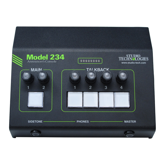
I/O interface or audio console can be supported. The Model 234 was designed to meet two main goals: supporting great audio quality and provid- With a total of six Dante audio inputs and an ing an extensive set of configurable features. - Page 6 ANNOUNCER’S CONSOLE The amount of flexibility provided in the Model connected using a 4-pin XLR connector. A 234 allows it to meet the needs of virtually all broadcast headset or handheld (“stick”) micro- on-air announcer applications. And using the phone can be directly connected to the unit’s Studio Technologies’...
- Page 7 MODEL 234 ANNOUNCER’S CONSOLE additional rotary controls allow adjustment of Audio input signals arrive into the Model 234 sidetone level and the overall level of the ana- by way of seven Dante receiver (input) chan- log headphone output. nels and pass into the Model 234’s 32-bit logic circuitry.
-
Page 8: Getting Started
1000BASE-T interconnections are made by connect an external source of 12 volts DC to way of Neutrik® etherCON RJ45 connectors. power the Model 234. If this is the case then While compatible with standard RJ45 plugs, a power supply would need to be provided etherCON allows a ruggedized and locking separately. - Page 9 One or Two Ethernet Connections An external source of 12 volts DC can be One 1000BASE-T (“GigE”) Ethernet connec- connected to the Model 234 by way of the tion is required for Model 234 operation and 4-pin male XLR connector which is located can provide both the Ethernet data interface on the back panel.
- Page 10 MODEL 234 ANNOUNCER’S CONSOLE redundancy, both PoE and the external source input could be connected to the Model 234 by can be connected at the same time. If both way of the analog microphone output con- PoE and an external 12 volts DC source are nector.
-
Page 11: Dante Configuration
No preamplifier or other active is configured such that it’s routed to the right circuitry impacts the path from the Model 234’s headphone output channel. Refer to the Con- analog microphone input connector to the figuration section later in this guide for details Model 234’s analog microphone output con-... - Page 12 MODEL 234 ANNOUNCER’S CONSOLE The Model 234 is also compatible with the that is being configured. The suffix’s actual Dante Domain Manager (DDM) software alpha and/or numeric characters relate to the application. Refer to DDM documentation MAC address of the unit’s Broadway integrat- for details on what Model 234 and related ed circuit.
-
Page 13: Model 234 Configuration
IP address or addresses. If Switched ensure that only one of the RJ45 knowledge of a Model 234’s IP address has jacks on the back panel is connected to the been misplaced there is no reset button or LAN associated with the Dante devices. - Page 14 Studio Technologies’ devices • Talkback – Button Function that it can control. The one or more Model 234 units to be configured will appear in the • Talkback – Impact on Main Output device list. Use the Identify command to allow •...
- Page 15 50 or 55 dB. first pass through the microphone preamplifier circuitry before it is used by the Model 234. An The “virtual” level meter provided in the audio signal that arrives by way of the Model STcontroller application will typically be used 234’s Dante Mic In receiver (input) channel...
- Page 16 This will typi- will provide a signal present display. Which cally not be an issue as the Model 234 has a configuration is selected will depend on the large amount of analog and digital headroom...
- Page 17 Dante Aux transmitter (output) channel. The Choices are Switched and Always On. microphone input source will, depending on On the Model 234’s back panel is a 3-pin a separate configuration choice, be either the male XLR connector that is labeled Mic Out.
- Page 18 Sidetone is audio from the selected mi- An eight-LED bar-graph level display is pro- crophone input source that is sent to the vided on the front panel of the Model 234. headphone output channels. This can be It can display the level of the selected mi- important, allowing a user to “hear”...
- Page 19 Button, Talkback 2 Button, Talkback 3 Button, 1 receiver (input) channel. Assigning it to the and Talkback 4 Button. left headphone output channel would again be appropriate. Model 234 User Guide Issue Preliminary 3, July 2020 Studio Technologies, Inc. Page 19...
- Page 20 Choices are Left, Right, and Left and Right. red when it’s inactive. Upon Model 234 power The phones routing for Dante Main 2 receiver up the main button will be in its inactive state (input) channel is similar to the routing for the and its red LED will be lit.
- Page 21 Talk mode except that an 18 kHz sine LED will be lit whenever the associated func- wave tone is added (summed) with the micro- tion is active. Upon Model 234 power up the phone audio. It is intended for use in REMI/ Model 234 User Guide Issue Preliminary 3, July 2020 Studio Technologies, Inc.
- Page 22 This might be ap- well as an intercom user station. propriate if a Model 234 is being used as an When 20 kHz Tone is selected and its associ- intercom station or stage manager console.
-
Page 23: Operation
15 dB which should work well for virtually flashing yellow. This call light function allows all applications. As previously mentioned, be- the Model 234 to be integrated into an inter- fore the signal is routed to the headphone out- com application that uses call signals. For... - Page 24 Dante interfaces begin to 234 is not synchronized with a Dante network. function. The various LEDs will then become It will light solid green when the Model 234 is operational, displaying the status of their as- synchronized with a Dante network and an sociated functions.
- Page 25 LED Intensity Microphone Source Selection On the Model 234’s front panel there are LED The Model 234’s microphone input source indicators associated with the five pushbut- can be selected, using STcontroller, to meet ton switches, six rotary encoders, and an the specific needs of an application.
- Page 26 Although a user probably won’t be aware of Model 234’s Dante receiver (input) channel. it, the Model 234 provides a Dante transmit- This is provided such that devices with Dante ter (output) channel designated as Aux. How...
- Page 27 Model it will flash red to indicate that it has been 234 can support. While the product’s title disabled. No voice or tone audio will be con- includes the text “Announcer’s Console,” that nected to the associated Dante transmitter doesn’t cover all the applications in which a...
- Page 28 Listen Mode input levels. A rotary potentiometer, located A unique STcontroller configuration mode al- on the left side of the Model 234’s front panel, lows each talkback input function to be indi- is used to adjust the sidetone level. Another...
- Page 29 Six rotary encoders are provided on the front of the Model 234 will indicate the approximate panel of the Model 234. Two of the encod- position of each of the rotary encoders. There ers are located above the main pushbutton are two ways to display the approximate posi- switch.
- Page 30 To clarify, if an encoder knob is lit when a tone is detected. This is provided so purple then any rotations of the knob will not that the Model 234 can be utilized in intercom be recognized. environments where call light signals are pres- Talkback Impact on Main Output ent.
-
Page 31: Technical Notes
“tally” output to directly light an LED talent cue (IFB) functionality to be created or activate an input on another piece of equip- directly within the Model 234. This can be ex- ment. For example, a 6- or 7-conductor XLR tremely useful in REMI/At-Home applications. - Page 32 Then by using the appropriate ARP command Two spare connector locations, labeled A the required “clues” can be obtained. It’s pos- and B, are provided on the Model 234’s back sible to make a direct connection between a panel. From the factory each contains a blank personal computer and a Model 234.
- Page 33 Ensure that the flex cable is not ing to a connector selected to be installed damaged while the Model 234 is being in a spare location on the Model 234’s back customized. panel. For reference, the wire color for pin 1 is gray, pin 2 is yellow, and pin 3 is blue.
- Page 34 Program audio would IFB controllers or devices such as the Studio enter the Model 234 by way of main input 1. Technologies’ Model 5422 Dante Intercom This would then be routed in STcontroller to Audio Engine.
- Page 35 12 volts DC. (Both must be disconnected revised files into non-volatile memory by way if for some reason dual-powering has been of a standard USB flash drive. The Model 234 implemented.) implements a USB host function and provides Model 234 User Guide Issue Preliminary 3, July 2020 Studio Technologies, Inc.
- Page 36 Model 234 will restart using the newly saved firmware. Restoring Factory Defaults 6. At this time the Model 234 will be function- A command in STcontroller allows the Model ing with the newly loaded firmware and the 234’s configuration selections to be reset to USB flash drive can be removed.
-
Page 37: Specifications
IEEE® 802.3ab (10 and 100 Mb/s not supported) Send Level: –20 dBFS Power-over-Ethernet (PoE): per IEEE 802.3af IFB (Dims Main Audio) Function: (applicable to Model 234’s Primary-PoE network connection only) Activation: in-band tone detection per Tone Detect function Analog Microphone Input:... - Page 38 Analog Microphone Input: 3-pin header located on the analog circuit board Spare Connector Locations: 2 Allows a Studio Technologies’ cable assembly or option module to be installed. Also compatible with Neutrik NC*D-L-1 connectors (*=3F, 3M, 5M, 6F, 6FS, etc.). Configuration: requires Studio Technologies’...
-
Page 39: Appendix A: Stcontroller Default Configuration Values
MODEL 234 ANNOUNCER’S CONSOLE Appendix A: STcontroller Default Model 234 Configuration Values General Menu Page: Microphone Input – Analog Mic In P48: Off Microphone Input – Source: Analog Mic In Microphone Input – Analog Gain: 50 dB System – Signal Present Display: All Inputs System –... -
Page 40: Appendix B: 3-Pin Header Connector Details
ANNOUNCER’S CONSOLE Appendix B: 3-Pin Header Connector Details The following list provides details on the 3-pin header connectors located on the Model 234’s printed circuit boards. Shown are both reference numbers and associated functions. I. Header on the Model 234’s Analog Board:... -
Page 41: Appendix C: Model 234 Block Diagram
MODEL 234 ANNOUNCER’S CONSOLE Appendix C: Model 234 Block Diagram The following block diagram shows a simplified version of the Model 234’s microphone input and microphone output circuitry. Model 234 User Guide Issue Preliminary 3, July 2020 Studio Technologies, Inc.
Need help?
Do you have a question about the 234 and is the answer not in the manual?
Questions and answers