Table of Contents
Advertisement
Quick Links
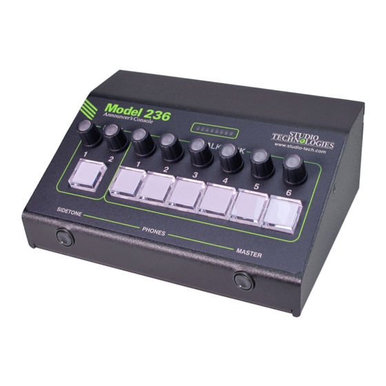
Model 236 Announcer's Console
User Guide
Issue 1, August 2020
This User Guide is applicable for serial numbers
M236-00151 and later with main firmware version 1.02
and STcontroller application version 2.10.00.
Copyright © 2020 by Studio Technologies, Inc., all rights reserved
www.studio-tech.com
50688-0820 Issue 1
Advertisement
Table of Contents

Related Manuals for Studio Technologies 236


Summary of Contents for Studio Technologies 236
- Page 1 User Guide Issue 1, August 2020 This User Guide is applicable for serial numbers M236-00151 and later with main firmware version 1.02 and STcontroller application version 2.10.00. Copyright © 2020 by Studio Technologies, Inc., all rights reserved www.studio-tech.com 50688-0820 Issue 1...
- Page 2 This page intentionally left blank.
-
Page 3: Table Of Contents
Technical Notes ................31 Specifications ................. 37 Appendix A: STcontroller default configuration values ....39 Appendix B: 3-Pin Header Connector Details ........ 40 Appendix C: Model 236 Block Diagram .......... 41 Model 236 User Guide Issue 1, August 2020 Studio Technologies, Inc. -
Page 4: Revision History
MODEL 236 ANNOUNCER’S CONSOLE Revision History Issue 1, August 2020: • Initial release. Issue 1, August 2020 Model 236 User Guide Page 4 Studio Technologies, Inc. -
Page 5: Introduction
I/O output. interface or audio console can be supported. The Model 236 was designed to meet two main With a total of eight Dante audio inputs and an goals: supporting great audio quality and pro- integrated sidetone function, users can eas- viding an extensive set of configurable features. - Page 6 ANNOUNCER’S CONSOLE The amount of flexibility provided in the Model connected using a 4-pin XLR connector. A 236 allows it to meet the needs of virtually all broadcast headset or handheld (“stick”) micro- on-air announcer applications. And using the phone can be directly connected to the unit’s Studio Technologies’...
- Page 7 This may also allow by way of nine Dante receiver (input) chan- the Model 236’s audio channels to support nels and pass into the Model 236’s 32-bit logic SMPTE® ST 2110-30. circuitry. Two channels are associated with Model 236 User Guide Issue 1, August 2020 Studio Technologies, Inc.
-
Page 8: Getting Started
(“GigE”) twisted-pair Ethernet interfaces. The connect an external source of 12 volts DC to 1000BASE-T interconnections are made by power the Model 236. If this is the case then way of Neutrik® etherCON RJ45 connectors. a power supply would need to be obtained While compatible with standard RJ45 plugs, separately. - Page 9 An external source of 12 volts DC can be con- One 1000BASE-T (“GigE”) Ethernet connec- nected to the Model 236 by way of a 4-pin male tion is required for Model 236 operation and XLR connector which is located on the back can provide both the Ethernet data interface panel.
- Page 10 No Model input to be selected. Details on configuration 236 action will impact that signal. If the analog settings will be described later in this guide. microphone output is configured to follow the...
-
Page 11: Dante Configuration
2-conductor (“tip and sleeve”) plug. When such amplification, and conversion to the digital do- a plug is inserted into the Model 236’s head- main. The output signals of an I/O interface’s phone output jack the right headphone output preamplifier channels are typically transported channel will be shorted;... - Page 12 Redundancy Using Dante Controller, the desired Dante The Model 236 allows connection of two Ether- transmitter (output) sources can be routed to net signals. Two RJ45 jacks are located on the nine Dante receiver (input) channels asso- the unit’s back panel and are labeled Primary-...
-
Page 13: Model 236 Configuration
MODEL 236 ANNOUNCER’S CONSOLE typically “crash” the network! (Although some Note that if the Model 236’s network configu- of the latest/most-advanced Ethernet switches ration has been set for Redundant then the will automatically detect and prevent such a Primary and Secondary Dante IP addresses “network bridging”... - Page 14 Studio Technologies’ devices • Talkback – Button Function that it can control. The one or more Model 236 units to be configured will appear in the • Talkback – Impact on Main Output device list. Use the Identify command to allow •...
- Page 15 Choices are 20 to 65 dB in 1-dB steps. The multi-purpose display, located on the When the Model 236’s microphone input front panel of the Model 236, can serve as an source is selected for Analog Mic In the gain 8-segment audio level meter which can be...
- Page 16 The eight rotary encod- Be aware that the Model 236 does not have ers are organized into two groups. One group any form of dynamic-range control. Audio consists of the two rotary encoders associ- “clipping”...
- Page 17 Choices are Switched and Always On. input source will always be present on the Dante Aux transmitter (output) channel. The On the Model 236’s back panel is a 3-pin male microphone input source will, depending on XLR connector that is labeled Mic Out. The...
- Page 18 If a “full mix” microphone level display function be turned off. is being supplied to the Model 236 then local- Remote Inputs / Tally Output – Overview ly provided sidetone won’t be needed and the Off configuration choice should be selected.
- Page 19 Remote Control In 1. the Dante Main 1 receiver (input) channel. A configuration choice allows the signal that arrives on Dante Main 2 to be routed to the Model 236 User Guide Issue 1, August 2020 Studio Technologies, Inc. Page 19...
- Page 20 Upon Model 236 power up the main button will be in its inactive Main – Button Mode state and its red LED will be lit.
- Page 21 Upon tions where a “pilot tone” needs to be sent Model 236 power up the function will be in its along with microphone audio. This is specifi- inactive state and its LED will not be lit.
- Page 22 18 kHz tone. This func- function becomes active. This might be ap- tion can allow a Model 236 to serve as both propriate if a Model 236 is being used in an an announcer’s console and an intercom user intercom station or stage manager console station.
-
Page 23: Operation
As previ- call is detected. This call light function allows ously mentioned, before the talkback signal the Model 236 to be integrated into an inter- is routed to the headphone output it will pass com application that uses high-frequency call through a low-pass filter (LPF) which removes signals. - Page 24 Initial Operation network activity. (The Model 236 has one Dante interface although single and redun- The Model 236 will start to function as soon as dant local area networks (Redundant Dante) a Power-over-Ethernet (PoE) or a 12 volts DC can be connected.) After lighting red and power source is connected.
- Page 25 Microphone Input Signal Active LED and software applications provide a function to Mic Preamp Gain allow specific Model 236 units to be identi- An LED indicator is located on the back panel fied. Both applications include an “eyeball” adjacent to the analog microphone input con- icon that when clicked will activate a specific nector.
- Page 26 Although a user probably won’t be aware of rectly utilized as the Model 236’s microphone it, the Model 236 provides a Dante transmit- source. Each microphone source, analog and ter (output) channel designated as Aux. How...
- Page 27 20 kHz sine ton function will change states. wave tone will be added (summed) with the audio present on all active Model 236 talk- Talkback Button Modes back channels that are configured to either The four talkback buttons can be indepen- the Talk or the Talk with 18 kHz Tone modes.
- Page 28 Model 236’s as both an analog headphone output, provid- selected microphone input source. Exactly how ed on the Model 236’s back panel by way of the sidetone function will operate will depend a 3-conductor ¼-inch jack, and in the form of on the STcontroller configuration setting.
- Page 29 For user assistance, the eight LEDs associated Eight rotary encoders are provided on the with the multi-purpose display on the front of front panel of the Model 236. Two of the rotary the Model 236 will indicate the approximate encoders are located above the main push- position of each of the rotary encoders.
- Page 30 In most cases the er’s function. For the signal level to be dis- Model 236 will be used on-air and the default played on the rotary encoder’s knobs requires mode, Mutes, will be appropriate. When this...
-
Page 31: Technical Notes
This is provided so that Configuration selections in STcontroller allow the Model 236 can be utilized in intercom en- these inputs to mimic the actions of the main vironments where call light signals are pres- and talkback pushbutton switches. - Page 32 The button covers are software application. In the unfortunate event clear with a white translucent lens underneath. that a specific Model 236’s IP address is “lost” As of the time of writing this guide the factory there are several techniques that may prove doesn’t have a recommended method as to...
- Page 33 (6 mm) label be created. Tape material that over the wire prior to soldering a connection! prints white text on a black background would be effective for use with the Model 236. The For details on each header’s reference Brother label cassette number TX-3151, white...
- Page 34 The actual action that creates an IFB “feed” program audio source also being routed to the within the Model 236 is very simple. If a tone left headphone channel would attenuate (“dim”) is detected on the audio signal arriving on the by 15 dB.
- Page 35 The STcontroller software application is used revised files into non-volatile memory by way to display the version numbers of the Model of a standard USB flash drive. The Model 236 236’s three firmware (embedded software) implements a USB host function and provides components.
- Page 36 Then click on the OK box. Refer to Appen- ing with the newly loaded firmware and the USB flash drive can be removed. But to dix A for a list of the Model 236’s factory default be conservative, remove the power source values.
-
Page 37: Specifications
IEEE® 802.3ab (10 and 100 Mb/s not supported) Send Level: –20 dBFS Power-over-Ethernet (PoE): per IEEE 802.3af IFB (Dims Main Audio) Function: (applicable to Model 236’s Primary-PoE network connection only) Activation: in-band tone detection per Tone Detect function Analog Microphone Input:... - Page 38 Analog Microphone Input: 3-pin header located on the analog circuit board Spare Connector Locations: 2 Allows a Studio Technologies’ cable assembly or option module to be installed. Also compatible with Neutrik NC*D-L-1 connectors (*=3F, 3M, 5M, 6F, 6FS, etc.). Configuration: requires Studio Technologies’...
-
Page 39: Appendix A: Stcontroller Default Configuration Values
MODEL 236 ANNOUNCER’S CONSOLE Appendix A: STcontroller Default Model 236 Configuration Values General Menu Page: Microphone Input – Analog Mic In P48: Off Microphone Input – Source: Analog Mic In Microphone Input – Analog Gain: 50 dB System – Signal Present Display: All Inputs System –... -
Page 40: Appendix B: 3-Pin Header Connector Details
ANNOUNCER’S CONSOLE Appendix B: 3-Pin Header Connector Details The following list provides details on the 3-pin header connectors located on the Model 236’s printed circuit boards. Shown are both reference numbers and associated functions. I. Header on the Model 236’s Analog Board:... -
Page 41: Appendix C: Model 236 Block Diagram
MODEL 236 ANNOUNCER’S CONSOLE Appendix C: Model 236 Block Diagram The following block diagram shows a simplified version of the Model 236’s microphone input and microphone output circuitry. Model 236 User Guide Issue 1, August 2020 Studio Technologies, Inc. Page 41...
Need help?
Do you have a question about the 236 and is the answer not in the manual?
Questions and answers