Table of Contents
Advertisement
Quick Links
Advertisement
Table of Contents

Subscribe to Our Youtube Channel
Related Manuals for Cosel TUNS1200F Series


Summary of Contents for Cosel TUNS1200F Series
- Page 1 Application manual TUNS1200F Rev. 1.1E 2021/11/22...
-
Page 2: Table Of Contents
Applications Manual for TUNS1200 Contents Page 1. Pin Assignment Pin Assignment 2. Connection for Standard Use Connection for standard use Input fuse : Input capacitor : Y capacitors and noise filters CY,CX,L11,L12 : Output capacitors Co,C40 : Smoothing capacitor for boost voltage :... -
Page 3: Pin Assignment
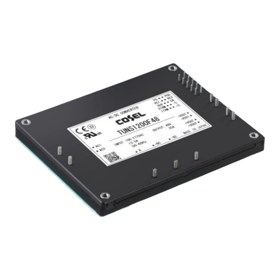
Applications Manual TUNS1200 1. Pin Assignment 2.1 Pin configuration 1.1 Pin Assignment Fig.1.1 Pin Assignment ⑲PG ⑭PGG ⑱RC1 ⑬RC2 ⑰AUX ⑫CB ⑯VTRM ⑪-S ⑮ITRM ⑩+S ①AC1 ⑨ -VOUT ②AC2 ⑧ ⑦ +VOUT ⑥ ③R ④+BC ⑤-BC 4-FG Bottom view Table 1.1 Pin configuration Function Connection... -
Page 4: Connection For Standard Use
Applications Manual TUNS1200 2. Connection for Standard Use 2.1 Pin configuration 2.1 Connection for standard use ■To use the TUNS1200 series, external components should be connected as shown in Fig.2.1. ■The TUNS1200 series should be conduction-cooled. Use a heatsink or fan to dissipate heat. Heatsink Fig.2.1 Connection for... -
Page 5: Input Capacitor: C11
Applications Manual TUNS1200 2.2 Input fuse: F11,F12 ■Fuse is not build-in on input side. In order to protect the unit, install a fuse shown in Table 2.2 in the input circuit. (as shown in Table 2.2) ■When applying for the medical electrical equipment standard, please install F11 and F12. Input voltage Table 2.2 Rated Voltage... -
Page 6: Output Capacitors: Co, C40
Applications Manual TUNS1200 2.4 Y Capacitors and noise filters: CY, CX, L11, L12 ■The TUNS1200 doesn't have noise filter internally Install an external noise filter and capacitor (CY) to reduce conducted noise and stabilize the operation of the power supply. ■Noise filters should be properly designed when the unit must conform to the EMI/EMS standards or when surge voltage may be applied to the unit. -
Page 7: Smoothing Capacitor For Boost Voltage: Cbc
Applications Manual TUNS1200 2.6 Smoothing capacitor for boost voltage: Cbc ■In order to smooth boost voltage, connect Cbc between +BC and -BC. Recommended capacitance of Cbc is shown in Table 2.4. ■If the capacity is not within the allowable external capacity, the module may be damaged. ■When operated below 0ºC, operation may become unstable as boost ripple voltage increases due to ESR characteristics. -
Page 8: Capacitor For Boost Voltage
Applications Manual TUNS1200 2.7 Capacitor for boost voltage :C20,C30 ■Install a film capacitor of 2uF or more into C20 and C30. ■If C20 and C30 are not connected, the power supply or external components could be damaged. ■Ripple current flows in. Check the maximum allowable ripple current of the capacitor when selecting. -
Page 9: Inrush Current Limiting Resistor: Tfr1
Applications Manual TUNS1200 2.8 Inrush current limiting resistor: TFR1 ■Install inrush current limiting resistor(TFR1) between R terminal and +BC terminal. ■If TFR1 is not connected, the power supply will not work. ■The surge capacity is required for TFR1. ■Wirewound resistor with thermal cut-offs type is required. ■Inrush current limiting resistor can be used to limit the primary inrush current. -
Page 10: Holdup Time
Applications Manual TUNS1200 3. Holdup time 2.1 Pin configuration 3.1 Input voltage characteristics of boosted voltage ■The boost voltage varies depending on the input voltage. Fig.3.1 Input voltage (430V) characteristics of boosted voltage (395V) (※1) (365V) Input voltage [VAC] ※1:If you adjust the output voltage to +10% or more, the BC pin voltage will increase. 3.2 Holdup time ■Holdup time is determined by the capacitance of Cbc. -
Page 11: Operation Under Low Temperature Conditions
Applications Manual TUNS1200 4. Operation Under Low Temperature Conditions 2.1 Pin configuration 4.1 Ripple voltage of boost voltage ■At low temperature, ripple voltage of boost voltage increases due to Cbc freezes. Select a capacitor of which ripple voltage of boost voltage does not exceed 30Vp-p on an actual operating condition. - Page 12 Applications Manual TUNS1200 Fig.4.2 Cbc = 780μF_ELXS501VSN391×2 parallel (MIN) Ripple voltage of BC by Ambient temperature AC200V Withstand voltage of Cbc : 500V -20℃ -30℃ -35℃ -40℃ Output current [%] Cbc = 1410μF_ELXS501VSN471×3 parallel (TYP) -20℃ -30℃ -35℃ -40℃ Output current [%] Cbc = 2350μF_ELXS501VSN471×5 parallel (MAX) -20℃...
-
Page 13: Parallel Operation
Applications Manual TUNS1200 5. Parallel operation 2.1 Pin configuration 5.1 Wiring for parallel operation ■Parallel operation is available by connecting the units as shown in Fig 5.1. ■Input capacitor C11, boost voltage circuit capacitor (Cbc, C20, C30) and Inrush current limiting resistor TFR1 cannot be used together. -
Page 14: Output Voltage Adjustment In Parallel Operation(Cv
Applications Manual TUNS1200 5.2 Output voltage adjustment in parallel operation(CV) ■When adjusting the output voltage in parallel operation, connect the VTRM terminals together and adjust them together. ■By connecting the external potentiometer(VR1) as shown in Fig.5.2.,output voltage becomes adjustable. See formula① 2 ×... -
Page 15: Constant Current Adjustment In Parallel Operation(Cc
Applications Manual TUNS1200 5.3 Constant current adjustment in parallel operation(CC) ■By adjusting the voltage of one ITRM, it is possible to adjust the constant current of all power supplies connected in parallel. It is not necessary to connect all ITRM terminals. ■By connecting the external potentiometer(VR2) as shown in Fig.5.4.,constant current becomes adjustable. -
Page 16: N+1 Redundant Operation
Applications Manual TUNS1200 5.4 N+1 redundant operation ■If you add one extra power supply in parallel operation, even if one of the power supplies in your system fails, the remaining power supplies continue to function. ■Use the load current with N power supplies, and keep the current per unit below the rated current x 0.9 or less. -
Page 17: Remote Control
Applications Manual TUNS1200 5.5 Remote control ■ When using remote control in parallel operation, control the remote control terminals of the power supplies in parallel at the same time, as shown in Fig.5.8 and 5.9. Fig.5.8. Ex.1)When the power output terminal and the remote control circuit are not isolated Remote control wiring example 1.1kΩ... -
Page 18: Other Functions
Applications Manual TUNS1200 6. Other functions Pin configuration 6.1 Power Good ■By using PG, it is possible to monitor power supply whether normal operation or abnormal operation. The PG signal is "Low" when the power supply operates correctly. The signal turns to "High" when the power supply stops. ■The PG signal sequence is shown in Fig6.1. -
Page 19: Mounting Method
Applications Manual TUNS1200 7. Mounting method 2.1 Pin configuration 7.1 Mounting method ■When implementing the power supply to the printed circuit board, please fix the power supply to the printed circuit board by screw before the soldering. If it is screwed to the substrate after soldering, there is a possibility of failure by adding mechanical stress to the soldering point and the internal connections of power supply. -
Page 20: Board Layout
Applications Manual TUNS1200 8. Board layout 2.1 Pin configuration 8.1 Consideration for board layout ■ The potential voltage of each terminal is given below. External components that are connected to these terminals should be at same potential voltage. Primary side(Input line) :... - Page 21 Applications Manual TUNS1200 ■When installing the electrolytic capacitor and the power supply on the same surface of the printed circuit board, please pay attention to the distance between the base plate and electrolytic capacitor. Exterior of the electrolytic capacitor is assumed to be the same potential as the negative electrode.
- Page 22 Applications Manual TUNS1200 ① Input fuse : F11 When the fuse is blown out, input voltage would be applied between the terminals of the fuse F11. Please keep the distance of the pattern between the terminals of the fuse more than 3mm if you must be complied safety approvals.
- Page 23 Applications Manual TUNS1200 ⑦ Output capacitors : Co, C40 Connecting the output capacitor (Co,C40) to the power module as close as possible for stable operation and radiation noise reduction. The output line impedance could cause unstable output voltage, which can be reduced by adding the output capacitor close to the load.
-
Page 24: Reference Pcb Layout
Applications Manual TUNS1200 8.2 Reference PCB layout Fig.8.4 Example of the pattern layout (Top view) (a) Example of the pattern and components layout (Top layer) (b) Example of the pattern and components layout (Bottom layer) Primary circuit Primary circuit Secondary circuit (AC input line) (Wiring to BC terminal) A-22... -
Page 25: Thermal Design
■Please refer to the applications manual "9.Thermal Considerations" on our website. Home> Technical Data> Application Guide ♦Power Module Type 9.Thermal Considerations https://en.cosel.co.jp/technical/app_guide/module_type/pdf/thermal_considerations.pdf 9.2 Examples of Convection cooling ■Here is an example of convection cooling with heatsink. ■Please consider this example as a design guideline because it changes by the heat dissipation environment. -
Page 26: Examples Of Forced Air Cooling
Applications Manual TUNS1200 Fig.9.3 Convection cooling 1400 measurement result 1200 1000 100VAC 200VAC 277VAC Ambient temperature [℃] ※Measurement results with TUNS1200F28 9.3 Examples of Forced air cooling ■Here is an example of forced air cooling with heatsink. ■Please consider this example as a design guideline because it changes by the heat dissipation environment. - Page 27 Applications Manual TUNS1200 Fig.9.6 Forced air cooling 100VAC measurement 1400 result 1200 1000 1.0m/s 2.0m/s Ambient temperature [℃] 200VAC 1400 1200 1000 1.0m/s 2.0m/s Ambient temperature [℃] 277VAC 1400 1200 1000 1.0m/s 2.0m/s Ambient temperature [℃] ※Measurement results with TUNS1200F28 A-25...
- Page 28 Applications Manual TUNS1200 Revision history No. date Rev. page content 2021.11.22 1.1E A-23 ~ A-25 「9 Thermal Design」 Addition A-26...
Need help?
Do you have a question about the TUNS1200F Series and is the answer not in the manual?
Questions and answers