Table of Contents
Advertisement
Quick Links
Basic Characteristics Data
LFA
Model
Circuit method
LFA10F
Flyback converter
LFA15F
Flyback converter
LFA30F
Flyback converter
Active fi lter
LFA50F
Flyback converter
Active fi lter
LFA75F
Flyback converter
Active fi lter
LFA100F
Forward converter
Active fi lter
LFA150F
Forward converter
Active fi lter
LFA240F
Forward converter
Active fi lter
LFA300F
Forward converter
*1
The value of input current is at ACIN 100V and rated load.
*2
Refer to Instruction Manual 2.
LFA-20
Basic Characteristics Data
Switching
Input
frequency
current
*1
[kHz]
[A]
100
0.26
100
0.35
130
0.65
60-440
0.67
130
60-440
1.0
130
60
1.3
140
60
2.0
140
60
3.3
140
60
4.1
140
Inrush
PCB/Pattern
current
Material
protection
LF
CEM-3
Thermistor
CEM-3
Thermistor
CEM-3
Thermistor
CEM-3
Thermistor
CEM-3
Thermistor
CEM-3
Thermistor
CEM-3
SCR
CEM-3
SCR
CEM-3
Series/Parallel
operation availability
Single
Double
Series
Parallel
sided
sided
operation
operation
Yes
Yes
No
Yes
Yes
No
Yes
Yes
No
Yes
Yes
No
Yes
Yes
No
Yes
Yes
No
Yes
Yes
No
Yes
Yes
No
Yes
Yes
No
*2
Advertisement
Table of Contents

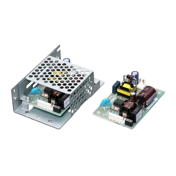
Summary of Contents for Cosel LFA10F
- Page 1 Model Circuit method frequency current current Single Double Series Parallel Material [kHz] protection sided sided operation operation LFA10F Flyback converter 0.26 CEM-3 LFA15F Flyback converter 0.35 Thermistor CEM-3 LFA30F Flyback converter 0.65 Thermistor CEM-3 Active fi lter 60-440 LFA50F 0.67...
-
Page 2: Table Of Contents
Instruction Manual AC-DC Power Supplies Open Frame/ Enclosed Type Function LFA-22 LFA-22 Input voltage range LFA-22 Inrush current limiting LFA-22 Overcurrent protection LFA-22 Overvoltage protection LFA-22 Output voltage adjustment range LFA-23 Output ripple and ripple noise LFA-23 Isolation LFA-23 Reducing standby power Series Operation and Parallel Operation LFA-23 LFA-23... -
Page 3: Function
Please contact us for details. comes intermittent so that the average current will also decrease. ¿ LFA10F, LFA15F, LFA30F, LFA50F, LFA75F, 1.4 Overvoltage protection LFA100F, LFA150F, LFA240F, LFA300F ¡... -
Page 4: Reducing Standby Power Lfa-23
Please make sure that no surrent ex- ¿ LFA10F, LFA15F ceeding the rated current fl ows into a power supply. ¡ A circuit reducing standby power is built in LFA10F and LFA15F. Power (standby power : 0.5W typ) -
Page 5: Assembling And Installation Method
, insert *Please refer to 3.4 if you want to extend the longevity of the ex- the insulation sheet between power supply and metal chassis. pectancy life. Table 3.1 Temperatures of Point A, Point B LFA10F- Mounting Cooling Max temperature... - Page 6 Instruction Manual AC-DC Power Supplies Open Frame/ Enclosed Type Table 3.2 Temperatures of Point A, Point B LFA15F- Table 3.5 Temperatures of Point A, Point B LFA75F- Mounting Cooling Max temperature Mounting Cooling Max temperature Load factor Load factor Point A[C] Point B[C] Point A[C] Point B[C]...
- Page 7 Note: In the hatched area, the specification of Ripple, Ripple Method Method 75% < Io[100% Noise is different from other area. 50% < Io[75% Convection ¿ LFA10F Io[50% 75% < Io[100% 50% < Io[75% (A), (D), (E), (F)mounting (B), (C)mounting Convection...
- Page 8 Instruction Manual AC-DC Power Supplies Open Frame/ Enclosed Type ¿ LFA75F ¿ LFA240F 1 (B)mounting 1 (C)mounting 1 (D), (F)mounting (D)mounting (C)mounting 1 (E), (F)mounting 1 (A), (B)mounting 1 (E)mounting 1 (A)mounting 2 (A) ~ (F) (A) ~ (F) mounting mounting 1Convection 1Convection...
-
Page 9: Mounting Screw Lfa-28
(F) positioning with case cover, tempera- ture / load derating is necessary. For more details, please contact ¡ Expectancy Life. our sales or engineering departments. Table 3.10 Expectancy Life (LFA10F- Mounting Cooling Average ambient Expectancy Life 3.3 Mounting screw... - Page 10 5years A,B,C,D,E,F Forced air Ta = 60C 5years 3years A,B,C,D,E,F Forced air Ta = 50C 5years 3years ¡ Warranty Table 3.14 Expectancy Life (LFA75F- Table 3.19 Warranty (LFA10F- Mounting Cooling Average ambient Expectancy Life Method Method temperature (year) Io[75% 75%<Io[100%...
-
Page 11: Ground
Instruction Manual AC-DC Power Supplies Open Frame/ Enclosed Type Table 3.22 Warranty (LFA50F- Table 3.26 Warranty (LFA240F- Mounting Cooling Average ambient Mounting Cooling Average ambient Warranty Warranty Io[75% 75%<Io[100% Io[75% 75%<Io[100% Method Method temperature (year) Method Method temperature (year) Ta = 40C or less 5years 5years Ta = 30C or less... - Page 12 -Refer to the adjustable range to the table 5.2 and table 5.3. -Option -H units can output the peak current. ¡ LFA10F, LFA15F, LFA30F, LFA50F, LFA75F -Peak load is possible to draw as below. Table 5.2 Output voltage adjustment range...
- Page 13 Instruction Manual AC-DC Power Supplies Open Frame/ Enclosed Type ¿ -R (LFA100F, LFA150F, LFA240F, LFA300F) ¿ -T (LFA240F, LFA300F) -You can control output ON/OFF remotely in Option -R units. To -Option -T units have vertically positioned screws on a terminal do so, connect an external DC power supply and apply a volt- block.
- Page 14 (load side), the output might become the stop or an unstable oper- ation. Please contact us for details when you connect the capaci- tor. ¿ LFA10F, LFA15F ¡ When these power supplies are connected to the input terminal in parallel, the total capacitance between line and line becomes big.


Need help?
Do you have a question about the LFA10F and is the answer not in the manual?
Questions and answers