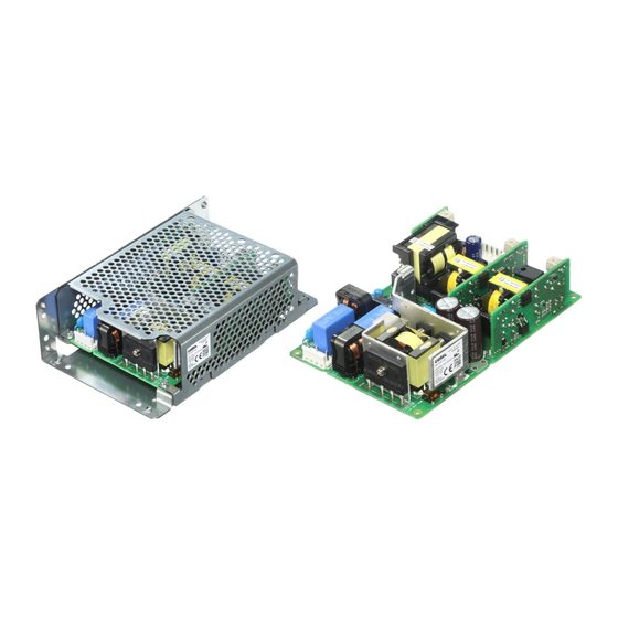
Table of Contents
Advertisement
Quick Links
Basic Characteristics Data
Model
Circuit method
Input module of
Active filter
RBC200F
Output module of
LLC resonant converter
Y, Z
Output module of
Flyback converter
G, H, J, K, L
Output module of
Flyback converter
M, P, Q
*1
The value at ACIN 100V and 200W output.
*2
Series operation is possible only if Slot 2 and Slot 3 are the same module. (Refer to Instruction Manual 3.1)
RB-6
Basic Characteristics Data
Switching
frequency
[kHz]
40 - 220
90 - 180
60 - 120
60 - 120
Input
Inrush
current
current
Material
[A]
protection
2.4
*1
Relay
FR-4
-
-
FR-4
-
-
FR-4
-
-
FR-4
Series/Parallel
PCB/Pattern
operation availability
Single
Double
Series
sided
sided
operation
-
Yes
No
-
Yes
No
-
Yes
Yes
*2
-
Yes
No
Parallel
operation
No
No
No
No
Advertisement
Table of Contents

Summary of Contents for Cosel RBC200F
- Page 1 Input module of Active filter 40 - 220 Relay FR-4 RBC200F Output module of LLC resonant converter 90 - 180 FR-4 Y, Z Output module of Flyback converter 60 - 120 FR-4 G, H, J, K, L...
- Page 2 Instruction Manual AC-DC Power Supplies Configurable Type Configuration - Model Name Construction RB-8 Function RB-9 Input voltage range RB-9 Inrush current limiting RB-9 Overcurrent protection RB-9 Overvoltage protection RB-9 Output voltage adjustment range RB-9 Output ripple and ripple noise RB-9 Isolation RB-9 Start/stop sequence...
- Page 3 (6 digits). Optional codes are not listed on Order Name. <Order Name Example> RBC200F - K J Y - 1 2 3 4 5 6 “1 2 3 4 5 6” is an example of management alphanumeric charac- ter.
-
Page 4: Output Voltage Adjustment Range
Instruction Manual AC-DC Power Supplies Configurable Type 2.5 Output voltage adjustment range 2 Function ¡ To increase an output voltage, turn a built-in potentiometer clock- wise. To decrease the output voltage, turn it counterclockwise. 2.1 Input voltage range ¡ The range is from AC85V to AC264V. (please see SPECIFICA- 2.6 Output ripple and ripple noise TIONS for details). -
Page 5: Series Operation
In case of malfunction (Failure of protection circuit activation), please stop the operation. The combined output voltage of series operation is 48 V. If the combined output voltage exceeds 60V, the safety agency approvals are void. RBC200F RBC200F Load Load Load Fig.3.1 Examples of wiring in series operation... -
Page 6: Installation Method
Instruction Manual AC-DC Power Supplies Configurable Type ¡ There is a possibility that it is not possible to cool enough when the power supply is used by the sealing up space as showing in Figure 4.6. Please use it after confirming the temperature of points 1 through 5 of section 4.1. -
Page 7: Outline Of Options
VH (hibox type) Fig.5.1 Derating curve depends on ambient temperature Output connector (RBC200F-O-SN) (Reference value) Function connector (optional) PH (hibox type) Table 5.4 Expectancy life (RBC200F-O-SN) ¿ -G Installation Cooling Average ambient Expectancy Life [years] - Option -G units are low leakage current type. - Page 8 Instruction Manual AC-DC Power Supplies Configurable Type ¿ -R 5.2 Others - You can control output ON/OFF remotely in Option -R units. To ¡ High voltage exists in the power supply for a few minutes after do so, connect an external DC power supply and apply a volt- input voltage is stopped.


Need help?
Do you have a question about the RBC200F and is the answer not in the manual?
Questions and answers