Hitachi SAMURAI Series Service Manual
Air cooled water chillers and air to water heat pump
Hide thumbs
Also See for SAMURAI Series:
- Service manual (137 pages) ,
- Service manual (140 pages) ,
- Manual (118 pages)

Related Manuals for Hitachi SAMURAI Series


Summary of Contents for Hitachi SAMURAI Series
- Page 1 SAMURAI SERIES AIR COOLED WATER CHILLERS AND AIR TO WATER HEAT PUMP -MODULAR-R134a-SCREW TYPE- Service Manual RCME-(40-70)AH1 RCME-(080-210)/(2-3)AH1 RHME-(40-70)AH1 RHME-(080-210)/(2-3)AH1...
-
Page 3: General Information
Contents C o n t e n t s General information Control Functions Servicing Troubleshooting SMGB0082 rev.1 - 07/2015... - Page 5 General Index General index General information ....................1 General notes ............................2 Safety and applied symbols ........................3 Product guide ............................4 1.3.1 Classification of water chiller models ......................4 1.3.2 Product guide: Air cooled water chillers (RCME) .................... 5 1.3.3 Product guide: Air to water heat pump (RHME) ....................6 Control Functions ...................... 7 2.1 Control functions on the module......................8 2.1.1 Water control ..............................11 2.1.2 Water temperature control ..........................
- Page 6 General Index 2.2.4 Overcurrent protection control ........................48 2.2.5 Defrosting (only for air-cooled heat pump systems (RHME)) ................ 49 2.3 Control of Master/Slave group....................... 52 2.3.1 Summary of control of Master/Slave group ....................52 2.3.2 Setting method .............................. 52 2.3.3 Operation method ............................53 2.3.4 Other functions of the control of Master/Slave group ..................56 2.3.5 Setting items ..............................58 2.3.6 Method for setting and confirmation of operation conditions through the LCD screen ........59 2.4 Run operation ............................61 2.4.1 ...
- Page 7 General Index 3.5.13 Replacement of the pressure relief valve ....................93 3.5.14 Replacement of the sight glass ........................93 3.5.15 Replacement of the crankcase heater (CH) ....................93 3.5.16 Replacement of the stop valve (x3) ......................94 3.5.17 Replacement of the thermistor (Suction, THMs) ..................94 3.5.18 Replacement of the thermistor (Discharge, THMd) ..................95 3.5.19 Replacement of the thermistor (x2) (Evaporation, THMr2) ................. 95 3.5.20 Replacement of the thermistor (Cooler water inlet, THMwi) ................ 96 3.5.21 Thermistor (Cooler water outlet, THMwo2) ....................96 3.5.22 Thermistor (Cooler water outlet, THMwo) ....................97 3.5.23 ...
- Page 8 General Index 4.9 Method for fault diagnosis ........................122 4.10 Troubleshooting by alarm code ......................123 4.11 Analysis and countermeasure of abnormalities................... 153 4.12 Thermistor characteristics ........................160 4.12.1 Thermistor temperature characteristics (All temperature except ambient and discharge gas) ....160 4.12.2 Thermistor temperature characteristics for ambient temperature ............. 160 4.12.3 Thermistor temperature characteristics for discharge gas temperature ............ 160 4.13 Pressure sensor characteristics ......................161 4.13.1 High-pressure sensor ..........................161 4.13.2 ...
- Page 9 1. General information G e n e r a l i n f o r m a t i o n Index General notes ............................2 Safety and applied symbols ........................3 Product guide ............................4 1.3.1 Classification of water chiller models ......................4 1.3.2 ...
-
Page 10: General Notes
1. General information General notes 1.1 General notes © Copyright 2014 HITACHI Air Conditioning Products Europe, S.A.U. – All rights reserved. No part of this publication may be reproduced, copied, filed or transmitted in any shape or form without the permission of HITACHI Air Conditioning Products Europe, S.A.U. Within the policy of continuous improvement of its products, HITACHI Air Conditioning Products Europe, S.A.U. reserves the right to make changes at any time without prior notification and without being compelled to introducing them into products subsequently sold. This document may therefore have been subject to amendments during the life of the product. HITACHI makes every effort to offer correct, up-to-date documentation. Despite this, printing errors cannot be controlled by HITACHI and are not its responsibility. As a result, some of the images or data used to illustrate this document may not refer to specific models. No claims will be accepted based on the data, illustrations and descriptions included in this document. No type of modification must be made to the equipment without prior, written authorisation from the manufacturer. HITACHI pursues a policy of continuing improvement in design and performance of products. The right is therefore reserved to vary specifications without notice. HITACHI cannot anticipate every possible circumstance that might involve a potential hazard. - Page 11 1. General information Safety and applied symbols 1.2 Safety and applied symbols During normal system design work or unit installation, greater attention must be paid in certain situations requiring particular care in order to avoid damage to the unit, the installation or the building or property. Situations that jeopardise the safety of those in the surrounding area or that put the unit itself at risk will be clearly indicated in this manual. To indicate these situations, a series of special symbols will be used to clearly identify these situations. Pay close attention to these symbols and to the messages following them, as your safety and that of others depends on it. D A N G E R • The text following this symbol contains information and instructions relating directly to your safety and physical wellbeing.
-
Page 12: Product Guide
1. General information Product guide 1.3 Product guide 1.3.1 Classification of water chiller models Basic modules Unit type (Modular water chiller): RCM: Air cooled water chiller RHM: Air to water heat pump E = Made in Europe Position-separating hyphen (fixed) Capacity (HP): 40, 50, 60, 70 A = Air cooled H = R134a refrigerant Series 1 R(C/H)M – Factory built modules combinations Unit type (Modular water chiller): Air cooled water chiller Air to water heat pump E = Made in Europe Position-separating hyphen (fixed) Total capacity (HP): 080, 090, 100, 110, 120, 130, 140, 150, 160, 170, 180, 190, 200, 210 Position-separating slash (fixed) - Page 13 1. General information Product guide 1.3.2 Product guide: Air cooled water chillers (RCME) Basic modules 3N~ 400V 50Hz Unit Code RCME-40AH1 8E041341 RCME-50AH1 8E051341 RCME-60AH1 8E061341 RCME-70AH1 8E071341 Factory built modules combinations 3N~ 400V 50Hz Modules of 2 units Code Modules of 3 units Code...
- Page 14 1.3.3 Product guide: Air to water heat pump (RHME) Basic modules 3N~ 400V 50Hz Unit Code RHME-40AH1 9E041341 RHME-50AH1 9E051341 RHME-60AH1 9E061341 RHME-70AH1 9E071341 Factory built modules combinations 3N~ 400V 50Hz Modules of 2 units Code Modules of 3 units Code RHME-080/2AH1 9E080201...
- Page 15 2. Control Functions C o n t r o l F u n c t i o n s Index Control functions on the module......................8 2.1.1 Water control ..............................11 2.1.2 Water temperature control ..........................12 2.1.3 Compressor Control ............................15 2.1.4 Control for recovery from power interruption (Option) ...................
- Page 16 2. Control Functions Control functions on the module 2.1 Control functions on the module List of the main control functions Item Description Slide valve control The outlet water temperature of the chiller unit is detected with a thermistor, and the stroke of slide valve is controlled continuously by time-sharing.
- Page 17 2. Control Functions Control functions on the module Item Description Anti-freezing for In order to prevent freezing caused by a decrease of water temperature in winter or under other low ambient winter temperature conditions, pump operation order is output automatically. (Automatic pump operation) N O T E...
- Page 18 2. Control Functions Control functions on the module Item Description It is possible to determine thermo OFF from the inlet water temperature (return temperature from load) of the chiller unit. It is possible to change the settings of thermo OFF temperature. Thermo OFF judgement due to N O T E...
-
Page 19: Water Control
2. Control Functions Control functions on the module 2.1.1 Water control Outlet water temperature of Chiller Unit is detected by Thermistor, and based on this value, compressor ON/OFF and the most suitable capacity is determined. Following shown the continuous capacity control and change of water temperature. Starting setting (example) Outlet... -
Page 20: Water Temperature Control
2. Control Functions Control functions on the module 2.1.2 Water temperature control 1 Automatic temperature adjustment Compressor run/stop and capacity control are performed by detecting water temperature of the chiller unit with thermistors. Water Temp Set ON/OFF Temperature Difference Stop Temperature Range Item Model Available range... - Page 21 2. Control Functions Control functions on the module 2 Method to change settings a. Water temperature settings This screen is displayed These screens are displayed when unit is setting in when unit is setting in only COOL/HEAT COOL only cool mode cool/heat mode The part with the setting temperature currently enabled is illuminated...
- Page 22 2. Control Functions Control functions on the module b. Setting of other water temperature control settings Continuous control type Display the input window with [INPUT] key Input the setting value with up and down keys Register the input value and close the window by pressing the [ENT] key.
-
Page 23: Compressor Control
2. Control Functions Control functions on the module 2.1.3 Compressor Control 1 Startup control The chiller unit receives an operation order, the cool (hot) water pump starts up, and after interlock is complete and compressor delay time (initial setting: 0.5 minutes) has passed, compressor is started up. In continuous control type, startup takes place in a state in which the slide valve is moved to the smallest load position. - Page 24 2. Control Functions Control functions on the module 4 Setting method of compressor delay time Display the input window with [INPUT] key Input the setting value with up and down keys Register the input value and close the window by pressing the [ENT] key. Also, by pressing the [CAN] key the input value is not registered, and the window is closed SMGB0082 rev.1 - 07/2015...
- Page 25 2. Control Functions Control functions on the module 2.1.4 Control for recovery from power interruption (Option) When this function is enabled, even in the case of power interruptions exceeding 2 seconds in length, operation restarts automatically in the operation mode as before the power failure, once a 3-minute guard has passed. To enable this function, the DIP switch of option C on the settings PCB (PCB ) (DSW5-1#) has to be set to ON.
- Page 26 2. Control Functions Control functions on the module 2.1.5 Prevention of simultaneous startup This function prevents simultaneous startup when supplying power to multiple units (in case that all modules are working individually, not in a master-slave group) In case that multiple chiller units are installed, it may be thought that all of them will start operation simultaneously when 3 minutes have passed after entering in recovery from power interruption.
- Page 27 2. Control Functions Control functions on the module 2.1.7 Anti-Freezing Control for Winter When operation is stopped during winter, the temperature of cold water decreases and may induce freezing of the water- side heat exchanger or the piping system. The outdoor temperature and cold water temperature are detected, to operate the cold water circulation pump automatically, and protect the chiller unit from freezing.
- Page 28 2. Control Functions Control functions on the module 2 Mode II Mode II is used mainly for systems containing multiple chiller units, or those with variable flow. To avoid alteration of the water temperature of the rest of chiller units in operation, the pump is operated with a low water temperature. Load △ Secondary pump Chiller unit Chiller unit Primary pump a.
- Page 29 2. Control Functions Control functions on the module Mode selection method In the case of air-cooled systems N O T E This control is not performed when [Disable] is selected. In this case, please make sure to implement anti-freeze measures on site, such as pump automatic operation or the installation of a heater at the water-side heat exchanger of the chiller unit.
-
Page 30: Demand Control
2. Control Functions Control functions on the module 2.1.8 Control for prevention of wrong operation and wrong settings In the following cases, an alarm is output as wrong operation. 1 Wrong activation of the operation controls A wrong operation alarm is displayed when there is a remote input (including external thermo signal) while the unit is stopped, regardless of "local/remote switch"... - Page 31 2. Control Functions Control functions on the module Current limit function (Power demand control) a. Contents of activation It is possible to operate below a maximum current limitation ratio previously set at the LCD screen. The selection to enable or release the setting value is performed with the order signal from the local control board. Also, the overcurrent protection control is always enabled, even in a state where this function is disabled.
- Page 32 2. Control Functions Control functions on the module c. Time chart Control setting value for overcurrent protection Maximum current Setting value of limitation value current limitation External signal X d. Wiring method Control board of the chiller unit Power Maximum current source of limitation switch the local control...
- Page 33 2. Control Functions Control functions on the module 2.1.10 Forced load up capacity control from external signal It is possible to force load up according to usage purpose. a. Contents of activation It is possible to force load up from the orders of local control panel. b.
- Page 34 2. Control Functions Control functions on the module 2.1.11 2-temperature setting function With respect to the setting temperature of water temperature control, it is possible to set 2 different temperatures, one for cooling and one for heating (only in the case of units with air-cooled heat pump), and select which of these to be used as a setting temperature by means of a remote signal.
- Page 35 2. Control Functions Control functions on the module 2.1.12 External thermo operation from external contact In case of setting the chiller unit to run/stop with the order of an external contact such as that of a (locally supplied) external thermo, capacity control function is disabled and operation is performed at 100% load. This function is mainly oriented to thermal storage operation.
- Page 36 2. Control Functions Control functions on the module Thermo OFF temperature of the main unit remains enabled even during forced load operation. When performing thermal storage from an external thermo, please set the external thermo to activate before the thermo OFF temperature of the main unit.
- Page 37 2. Control Functions Control functions on the module 2.1.13 Water Temperature of the Control Target It is possible to select which water temperature to use for capacity control and thermo OFF judgement, either "Inlet" or "Outlet". Please use the outlet water temperature (factory default setting) in normal conditions. ...
- Page 38 2. Control Functions Control functions on the module 2.1.14 Operation from DC24V contact input Outline The procedure to control operation from the DC24V contact of the local central controller is shown below. • Level input • Pulse input (1 switch) •...
- Page 39 2. Control Functions Control functions on the module b. Setting method In the case of air-cooled systems N O T E • Please do not bundle the additional wiring together with other control circuits, and in particular with wiring for 230V or 400V.
- Page 40 2. Control Functions Control functions on the module Pulse input type 1 a. Signal aspect and basic sequence For wiring Terminal board Section arranged as a local work Run/stop switch (to be prepared locally) Alarm output (DC24V, less than 0.8A) Relay coil for DC24V, etc.
- Page 41 2. Control Functions Control functions on the module b. Setting method In the case of air-cooled systems Select "Pulse" N O T E • Please do not bundle the additional wiring together with other control circuits, and in particular with wiring for 230V or 400V.
- Page 42 2. Control Functions Control functions on the module Pulse input type 2 (external DC24V source) a. Signal aspect and basic sequence For wiring Please remove (ON) signal (OFF) signal (OFF) (ON) Local works - parts to be arranged locally (field supplied) Time chart More than 5 min...
- Page 43 2. Control Functions Control functions on the module 2.1.15 Attachment of snowfall switch (Forced fan operation) In regions with snowfall, when installing a snowfall switch in the context of countermeasures to prevent the accumulation of the snow while the chiller unit is stopped, the snowfall switch has to be wired to terminals [26] and [24] of terminal board TB3 of the control circuit of the electrical box.
- Page 44 2. Control Functions Control functions on the module 2.1.16 Silence priority mode (Night shift) (Only in cooling operation) It is possible to operate with a reduced fan noise, for instance at night. Silence priority mode becomes enabled by the input of non-voltage contact.
- Page 45 2. Control Functions Control functions on the module 2.1.17 Thermo OFF function selection This function prevents thermo OFF of the chiller unit due to sudden changes of temperature or flow. Example of standard settings: Inlet water temperature Outlet water temperature Setting temperature Thermo OFF temperature Stop with 10 continued seconds at thermo OFF temperature Example of thermo OFF judgement extension Inlet water temperature Outlet water temperature 10 minutes...
- Page 46 2. Control Functions Control functions on the module Mode selection method In the case of air-cooled systems Select "10 minutes" 2.1.18 Selection of enabling/disabling of alarm release by means of remote stop The release of an alarm in case that the chiller unit has stopped due to an alarm is achieved by stop control (it is possible to stop both from the stop button of the main unit or from remote stop control). But it is possible to configure this alarm release ...
- Page 47 2. Control Functions Control functions on the module 2.1.19 Limitation setting for pump feedback waiting time Flow at the start of operation of the chiller unit ° Chiller Unit Operation Order Reception Waiting for Pump Feedback ¢ Interlock achieved In case that setting time is Compressor operation after compressor delay £...
- Page 48 2. Control Functions Control functions on the module 2.1.20 Inlet water temperature thermo OFF function Normally thermo OFF judgement is carried out from outlet water temperature, but when enabling this setting, the judgement of thermo OFF is carried out also from inlet water temperature. (Thermo OFF judgement by outlet water temperature is also enabled)(Water temperature control is carried out from outlet water temperature even in case that this function is enabled ) It is effective when there is the need to set thermo OFF with the return water temperature from the load.
- Page 49 2. Control Functions Control functions on the module 2.1.21 Intermitent fan operation The fan operates automatically, to prevent freezing of the fan due to snowfall when the unit is stopped in winter. Starting conditions • Outdoor temperature under 4ºC The fan is operated when all of •...
- Page 50 2. Control Functions Control functions on the module 2.1.22 Switch for confirmation of high pressure cut. (Cooling operation). By switching to this test mode, it is possible to force the activation of high pressure switch device, which simplifies the task of checking the activation of high pressure switch, when it might be necessary for circumstances such as test run. Method of operation Switch for High pressure cut check check test...
- Page 51 2. Control Functions Control functions on the module N O T E • It is disabled when in remote settings. • High pressure rises slowly in circumstances such as right after starting up the compressor (during startup control), and other protection controls may activate first with a certain probability. It is recommended to use this switch in a state where operation capacity is close to 100%.
- Page 52 2. Control Functions Control of the cooling cycle 2.2 Control of the cooling cycle 2.2.1 Compressor Control The compressor mounted on this product is equipped with a system to adjust the amount of discharge (slide valve). The slide valve is installed on the screw rotor, and performs the adjustment of the amount of discharge with the change of bypass amount by hydraulic activation.
-
Page 53: Fan Control
2. Control Functions Control of the cooling cycle 2.2.2 Fan Control 1 Cooling operation This product uses fan revolution control by means of inverter to control high pressure. The target pressure is set from outdoor temperature, and the variation of the number of revolutions is managed by PI control. -
Page 54: Expansion Valve Control
2. Control Functions Control of the cooling cycle 2.2.3 Expansion Valve Control The expansion valve used in this product is an electronic expansion valve. The electronic expansion valve is composed by the main unit and a coil. The control functions of the electronic expansion valve are as shown below. 1 Basic control ... - Page 55 2. Control Functions Control of the cooling cycle 2 Protection controls The basic control follows the contents of section 1, but the following functions are also implemented for the protection of the product. a. Low pressure over-increase prevention control In case of continued operation conditions of low pressure higher than 0.5 MPa, the valve is forced to close and momentarily set somewhat close in comparison with the opening under normal control.
- Page 56 2. Control Functions Control of the cooling cycle Image diagram of 0 (zero) point adjustment If the compressor does not stop in 200 hours Restart after 3 minutes In superheat control Thermo OFF Thermo ON Time If more than 24 hours have passed since the last 0 (zero) point Forced 0 (zero) point adjustment adjustment, then 0 (zero) point adjustment is performed during is performed...
- Page 57 2. Control Functions Control of the cooling cycle 2.2.5 Defrosting (only for air-cooled heat pump systems (RHME)) Outdoor temperature, evaporation temperature and evaporation pressure are detected during heating operation, and in case that an amount of frost formation is detected, the 4-way valve is switched and defrosting operation is conducted in reverse cycle.
- Page 58 2. Control Functions Control of the cooling cycle Defrosting operation flow Fulfilment of conditions to start defrosting Compressor capacity control hold 10 seconds count Fan 0 Hz order. Switching of 4-way valve 10 seconds count Inlet refrigerant temperature of water- side heat exchanger (Tr ≤ 0ºC Compressor load down output (5 seconds output) Tr ≤ 2ºC Compressor load up output (5 seconds output)
- Page 59 2. Control Functions Control of the cooling cycle (From previous page) Fulfilment of conditions to finish defrosting Compressor forced load down output In fan operation Fan 7 Hz order output *Pd: High pressure (COO72CN-3Pd) Pd* ≥ 1.5 MPa 19 seconds have passed since 7 Hz order output Fan maximum frequency operation start Pd* ≤ 1.0 MPa 60 seconds have passed since maximum frequency Switching of 4-way valve...
-
Page 60: Setting Method
2. Control Functions Control of Master/Slave group 2.3 Control of Master/Slave group 2.3.1 Summary of control of Master/Slave group In addition to the operation as a single chiller unit, this product allows the operation of multiple chiller units as a single heat source system. 1 Features •... -
Page 61: Operation Method
2. Control Functions Control of Master/Slave group 2.3.3 Operation method One group composed of multiple modules using the functions to control the number of units is called a "system". 1 Operation Order (Required) Please input "System Operation Order" for the chiller unit set as Unit 1. It is also possible to put the system to operation from the "Local system operation switch"... - Page 62 2. Control Functions Control of Master/Slave group 4 Remote display wiring Output from unit 1 only Output from each unit Notes 〇 System Operation Output from terminal No.23. 〇 System cooling/heating mode Air-chilled heat pump only 〇 Chiller Unit (Module) Operation 〇 Pump Operation 〇...
- Page 63 2. Control Functions Control of Master/Slave group 5 Remote Forced Stop (Alarm Reset) / System Recovery Wiring Connect to each chiller unit to force stop of a chiller unit in operation from a remote location, to reset an alarm, or to return to the system a chiller unit that had been excluded from the target of the control of Master/Slave group. When a chiller unit is stopped because of an alarm, or by a forced stop order, it becomes excluded from the target of the control of Master/Slave group (detached). It is necessary to perform system recovery operation in order to regain ...
- Page 64 2. Control Functions Control of Master/Slave group 6 Forced operation order wiring. (External thermo operation) When connecting forced operation wiring, it is possible to operate a specific chiller unit. (This is possible also during system operation). However, this is only for chiller units which are stopped. Also, in the case of air-cooled heat pump systems, the chiller units to which a forced operation order has been input operate in the state of remote cooling/heating switching signal, so it is necessary to properly connect the cooling/ heating switching wiring as well.
-
Page 65: Cooling Operation
2. Control Functions Control of Master/Slave group 5 About mixing of heat pump machines It is possible to install heat pump units and cooling-only units in the same group. In that case, operation becomes as follows: Cooling operation: All the chiller units become target of the control of number of units. Heating operation Only the heat pump units become target of the control of number of units. -
Page 66: Setting Items
2. Control Functions Control of Master/Slave group 2.3.5 Setting items Inlet water temperature § Number of Units at Startup Water temperature Sets the number of modules to be started up upon Addition ¥ system start-up. Addition Maximum number of operating units Sets the upper limit of the number of modules that can £... - Page 67 2. Control Functions Control of Master/Slave group 2.3.6 Method for setting and confirmation of operation conditions through the LCD screen Conducts the setting of the control of Master/Slave group and confirmation of operation conditions through the LCD screen. [Setting screen of the control of Master/Slave group] In the case of master In the case of slave unit unit (unit 1) setting (units 2 to 8) setting Set the setting temperature difference (when the 1st water temperature setting is enabled) Set the setting temperature difference (when the 2nd water temperature setting is enabled)
- Page 68 2. Control Functions Control of Master/Slave group [Status screen of the control of Master/Slave group] The operation status of each unit is shown by pressing the keys "2" to "8" SMGB0082 rev.1 - 07/2015...
- Page 69 2. Control Functions Run operation 2.4 Run operation 2.4.1 Setting of switches on the setting PCB 1 High pressure check cut button (in cooling operation) By pressing the button during cooling operation, the High pressure cut check operation of the fan stops. It is a button for confirmation No. 1 No. 2 of the activation value of high pressure cut. PSW3 PSW4 Low cut test (in heating operation)
- Page 70 2. Control Functions Run operation 2.4.2 Operation control of the module 1 In the case of remote control Operation order Confirm that the cold (hot) water inlet/outlet valve is fully open Power ON Power ON the pump for cold water circulation Cooling Heating Set the locally installed “Cooling/Heating” switch to “Cooling” Set the locally installed “Cooling/Heating” switch to “Heating” Press the “Run” button Operation of pump for cold (hot) water circulation starts Operation of fan and compressor starts after compressor delay time has passed Stop order Press the “Stop”...
-
Page 71: Time Chart
2. Control Functions Time chart 2.5 Time chart Cooling operation Continous capacity control (Cooling operation) Power source Run control Control Stop control Heating (ON)/Cooling(OFF) Pump feedback Protection device Common (Other than above) Load Thermo Load Load Thermo Load up 2 down Power source display (Main unit) Pump operation Pump operation display (Remote) -
Page 72: Heating Operation
2. Control Functions Time chart Heating operation Continuous capacity control (Heating operation) Start - Stop of operation Power source Run control Control Stop control Heating (ON)/Cooling (OFF) 10 s Pump feedback P r o t e c t i o n device Common (Other than above) Load Thermo Load... -
Page 73: Defrosting Operation
2. Control Functions Time chart Defrosting operation Continuous capacity control (Heating operation) Defrosting during heating operation - Cooling operation after heating opeation stop Power source Run control Control Stop control Heating (ON)/Cooling (OFF) Pump feedback 10 s P r o t e c t i o n device Common (Other than above) Load... - Page 75 3. Servicing S e r v i c i n g Index LCD display for Service Menu ....................... 69 General notes ............................77 Access inside the module for servicing ....................77 Removing covers........................... 78 3.4.1 Unit description .............................. 78 3.4.2 Panels on the left (2 panels) or right side (2 panels)..................79 3.4.3 Front cover (E-Box - compressor side) ......................
- Page 76 3. Servicing Electrical components ........................... 99 3.6.1 Replacement of the electrical box assy ......................99 3.6.2 Open electrical box doors ..........................100 3.6.3 Replacement of lamps and push buttons ....................101 Removal of the PCB’s ............................102 3.6.4 Removal of the LCD screen ........................104 3.6.5 Transformer (TF1) ............................
- Page 77 3. Servicing LCD display for Service Menu 3.1 LCD display for Service Menu INPUT SCREEN EXAMPLE (Latest version will be shown) (2 sec.) MAIN SCREEN MENU N O T E This screen will be shown after clicking on the INPUT button. Increases the value.
- Page 78 3. Servicing LCD display for Service Menu Auto expansion valve initialize SERVICE MENU SCREEN (1/2) Superheat setting SERVICE MENU SCREEN (1/2) SMGB0082 rev.1 - 07/2015...
- Page 79 3. Servicing LCD display for Service Menu Expansion valve manual operation SERVICE MENU SCREEN (1/2) Overcurrent protection setting SERVICE MENU SCREEN (1/2) SMGB0082 rev.1 - 07/2015...
- Page 80 3. Servicing LCD display for Service Menu Sensor adjust SERVICE MENU SCREEN (1/2) N O T E When a sensor is giving a different value than the actual value, a correction can be set. Example: Real temperature: 25.0º C Thermistor value: 24.0º...
- Page 81 3. Servicing LCD display for Service Menu Comp Hr Setting SERVICE MENU SCREEN (1/2) N O T E When PCBb is replaced, the previous information related to compressor operating time and number of restarts can be entered form the service menu ...
- Page 82 3. Servicing LCD display for Service Menu 4-20 mA input SERVICE MENU SCREEN (/2) Continuous control SERVICE MENU SCREEN (/2) Order dissable SERVICE MENU SCREEN (/2) SMGB0082 rev.1 - 07/2015...
- Page 83 3. Servicing LCD display for Service Menu Default Set SERVICE MENU SCREEN (/2) N O T E • This function resets all data and returns to the initial values, except for the warning and alert history and accumulated operating time-period and operating time of the compressor. •...
- Page 84 3. Servicing LCD display for Service Menu Delete log SERVICE MENU SCREEN (/2) N O T E This function deletes the stored data concerning to the alarms and cautions. SMGB0082 rev.1 - 07/2015...
- Page 85 3. Servicing General notes 3.2 General notes Before starting to remove any component, take into account the following notes: D A N G E R • Before performing any of the service operations described in this chapter, turn all the main switches off and place security lockers or convenient warning indicators in order to prevent them from turning on accidentally.
-
Page 86: Front View
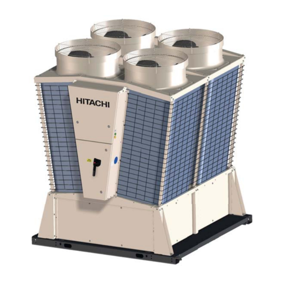
3. Servicing Removing covers 3.4 Removing covers 3.4.1 Unit description Front view Fans (x4) Electrical box (Upper box) Electrical box (Lower box) Front Cover Right Cover (x2) Rear view Air cooler protection (grille) Air cooler panels Water pipe (inlet) Water pipe (outlet) Left Cover (x2) Rear Cover (x2) SMGB0082 rev.1 - 07/2015... - Page 87 3. Servicing Removing covers 3.4.2 Panels on the left (2 panels) or right side (2 panels). Each panel have two locks. With the key (female square key), turn the locks 1/4 and remove the cover by pulling it. N O T E All locks have a mark: ▲...
- Page 88 3. Servicing Removing covers 3.4.4 Front cover (Hex lower cover) 1 Remove the 6 bolts at the front of the cover 6 screws 2 Remove the 2 screws at each corner of the HEX 2 screws lower cover. 3 Inside of the unit, remover the 4 screws fixing 2 + 2 screws the supports of the HEX lower cover 3.4.5 Rear cover (water connection side)
- Page 89 3. Servicing Removing covers Each panel have two locks. With the key (female square key), turn the locks 1/4 and then the cover is free to be removed. 3.4.6 Water pipes support Remove both rear covers and disconnect de water pipe (Victaulic connection). Remove two screw at the top of water pipe support and two screw at bottom (from inside side) SMGB0082 rev.1 - 07/2015...
- Page 90 3. Servicing Removing covers 3.4.7 Protection net (Air cooler grille) Each Module is equipped with 4 protection net, each one fixed to the structure with 12 screws. Ambient thermistor C A U T I O N In the front left protections net (electrical box side) is installed the ambient thermistor. Remove the ambient thermistor before the removal of the protection net.
-
Page 91: Compressor Removal
3. Servicing Cycle components 3.5 Cycle components C A U T I O N • All operations in the refrigerant cycle require to collect the refrigerant. In those cases proceed as explained in “3.5.3 Recovering the refrigerant” D A N G E R •... - Page 92 3. Servicing Cycle components For RHME models only Bolt (x4) 6 Remove the 4 bolts from the flange of the si- lencer. Bolt Spring washer Flange plate 7 Remove the screws fixing the clamps and gen- tly pull the silencer to give some space when removing the compressor.
- Page 93 Cycle components 3.5.2 Overhaul work Perform the work according to “Semi-hermetic Hitachi Screw Compressor Manual”. When removing a compressor from the refrigeration cycle, high pressure part shall be separated between the projecting part flange of compressor and the upper cover of oil separator. Do not separate high pressure part between the check valve and the projecting part flange of compressor, as collected refrigerant would be spilled out.
- Page 94 3. Servicing Cycle components Refrigerant gas suction inlet (65A) Refrigerant gas discharge outlet (50A) Check joint (Discharge pressure release) (1/4 flare nut) Check joint (100% detection hole) (1/4 flare nut) Oil extraction level Oil heater (3/8 plug) gauge Check joint (Suction pressure release) Oil extraction Oil strainer cover (1/4 flare nut)
- Page 95 3. Servicing Cycle components 3.5.4 Replacement of the Brazed plate heat exchanger Remove the rear panel as detailed in chapter “3.4.5 Rear cover (water connection side)”. Remove the water pipes support as described in section “3.4.6 Water pipes support” 1 Remove the thermistors THMr2 as explained in Thermistor THMr2(x2) chapter ““3.5.19 Replacement of the thermistor...
- Page 96 3. Servicing Cycle components 5 Remove the pressure differential assembly as Flare nut for pres- sure differential described in chapter device (inlet) Water inlet pipe Pressure differential device Flare nut for pres- sure differential Water outlet pipe device (outlet) 6 Remove the water inlet and water outlet pipes. Water inlet pipe Remove the Victaulic couplings from their attachment.
- Page 97 3. Servicing Cycle components 3.5.5 Replacement of the expansion valve For R(C/H)ME models there are different number of electronic expansion valves. While R(C/H)ME-70AH1 have 3 elec- tronic expansion valves (2 at the evaporation circuit plus 1 at the inlet of the economiser), R(C/H)ME-(40-50)AH1 models have only two electronic expansion valves (at the evaporation circuit).
- Page 98 3. Servicing Cycle components Pay attention to the following points when replacing an expansion valve. a. This unit uses an electronic expansion valve, which is normally closed when the compressor stops. For this reason, when the valve upstream of the expansion valve (liquid outlet valve of the heat exchanger) is closed, refrigerant may accumulate between the liquid outlet valve of the heat exchanger and the expansion valve.
-
Page 99: Filter Drier
3. Servicing Cycle components 3.5.7 Filter drier There are two possible main maintenance operations to do with the filter drier: the substitution of the inner core due to its adsorption saturation or the substitution of the whole unit due to some damage. ... - Page 100 3. Servicing Cycle components 3.5.8 Replacement of the stop valve (with check joint) 1 Remove the brazed parts using a blowtorch and Stop valve Check joint previously cooling the pipe side and the stop valve unit with wet cloth in order to avoid braz- ing material enter inside the pipes.
- Page 101 3. Servicing Cycle components 3.5.12 Replacement of the pressure sensor (PSW) 1 Disconnect the cables (7 and 8) of the Pressure sensor from the E-box of the compressor termi- nal board). 2 Unscrew the sensor and proceed to its replace- ment Pressure sensor (PSW)
- Page 102 3. Servicing Cycle components 3.5.16 Replacement of the stop valve (x3) There are 3 stop valves located along the refrigerant cycle: 2 are located close the expansion valves and 1 is located at the filter drier, as shown in the pictures below. To replace the stop valves, unscrew the stop valve with a spanner.
- Page 103 3. Servicing Cycle components 3.5.18 Replacement of the thermistor (Discharge, THMd) 1 Cut and remove the plastic bands that fixes the insulation of the discharge pipe thermistor (THMd). 2 Loosen the screw fixing the thermistor. 3 At the E-box, disconnect the CN26TD contact (or the Faston terminals 4A and 4B of multiple contact QCN3) 4 Remove the thermistor.
- Page 104 3. Servicing Cycle components 3.5.20 Replacement of the thermistor (Cooler water inlet, THMwi) 1 Unscrew the nut of the cable gland 2 Gently pull the sensor wiring upwards. C A U T I O N Sensor sheath is full of sealing silicone. Use gloves and eye goggles for protection in order to avoid possible injuries to eyes and skin.
- Page 105 3. Servicing Cycle components 3.5.22 Thermistor (Cooler water outlet, THMwo) To remove the thermistor THMwo, proceed as follows: 1 Unscrew the nut of the cable gland 2 Gently pull the sensor wiring upwards. Sensor wiring C A U T I O N Cable gland Sensor sheath is full of sealing silicone.
- Page 106 3. Servicing Cycle components 3.5.25 Removing the differential pressure device (optional) To proceed to the removal of the differential pressure device, follow the next steps: 1 Remove the rear cover as explained in chapter Flare nut for pres- sure differential 2 Remove the flare nut of the water inlet pipe.
-
Page 107: Electrical Components
3. Servicing Electrical components 3.6 Electrical components 3.6.1 Replacement of the electrical box assy 1 Unplug the connectors located rear to the electrical box. Do this operation from inside the Chiller module. QCN7 QCN3 QCN5 QCN4 QCN8-1 QCN8-2 QCN13 QCN1 QCN2 2 Place lifting rings on the top of electrical box. - Page 108 3. Servicing Electrical components 5 Remove the 10 screws situated in he each side (5 in right Left side Right side side and 5 in the left). 6 Lift slowly the electrical box until free and separate from the chiller module Screws (x5) Screws (x5) 7 To install the electrical box follow the process described in...
- Page 109 3. Servicing Electrical components Open Upper door The door opens upward. Turn 1/4 the 2 locks and the air Air press stay press stay will open to the door. Open lower door Prior to open the door be sure that the main switch is in OFF position.
- Page 110 3. Servicing Electrical components Removal of the PCB’s Transformers (TF) PCBc PCBd PCBa ON/OFF buttons LCD screen PCBa 7- segment display Pressure switches (PSW) Plastic holder PSW1, PSW2 Switches (SW) Plastic holder SW1, SW2 Pressure switches (PSW) PSW3, PSW4 PSW5 PSW6 a.
- Page 111 3. Servicing Electrical components PCBc Plastic holder Plastic holder a. Remove the PCB by pressing the expanded part of the 4 plastic holders, using long-nose pliers, as shown in the picture. b. Pull the PCB out from the PCB plate.
- Page 112 3. Servicing Electrical components Fan PCB (PCBE1, PCBE2, PCBE3 and PCBE4) Fan PCB are at the lower level of the electrical box. Access to fan PCBs is described next: 1 Open the upper door of the electrical box 2 Remove the plastic protection as described in the next chapter,”3.6.4 Removal of the LCD screen”.
- Page 113 3. Servicing Electrical components 3 Firmly pull the metallic plate where the LCD screen is at- tached in order to have access to the rear side of the LCD screen. Firmly pull until release the fixation assembly 4 Access to the rear side of the LCD screen is now avail- able.
- Page 114 6 Using a Phillips screwdriver, loosen the 4 screws fixing Screws (x4) the LCD screen to the door panel. 7 For a correct removal of the LCD screen, follow the next steps 1.- Loosen the screw 2.- Push the hook 3.- Pull the hook backwards 3.6.5 Transformer (TF1) To have access to electrical transformer TF1, follow the steps described in...
- Page 115 3. Servicing Electrical components 3.6.7 Overcurrent relay (ORC) To remove the overcurrent relay (ORC), open the E-box, and follow the next steps. 1 Remove all the wirings. 2 Remove the 2 screws that fix the ORC to the plate. 95 NC 96 NC Ru(Brown) Sv (Black)
- Page 116 3. Servicing Electrical components 3.6.9 Fuses (EF1, EF2, EF3. EFR, EFS, EFT) “EF” fuse series are mounted on DIN rail. To replace any damaged fuse proceed as described below. 1 Once the damaged fuse is detected, simply push the holder down. The damaged fuse appears. Pull it and proceed to its replacement 3.6.10 Fuses (PFC) ...
- Page 117 3. Servicing Electrical components 1 Pull the fuse housing backwards. 2 Remove the Hex screws and wiring. PFC3-5 PFC1-1 PFC2-3 3 Remove the Phillips screws and replace the fuse holder. 2 Phillips 3+3 Flat screw driver screwdriver or 13mm spanner PFC1-2 PFC2-4 PFC3-6...
-
Page 118: Main Switch
3. Servicing Electrical components 3.6.12 Main Switch To remove the main switch, follow the next steps 1 Turn the switch of in order to be able to open the E box MIT/L3 MIS/L2 MIR/L1 door 2 Open the E-box door. 3 Remove the wiring. - Page 119 4. Troubleshooting T r o u b l e s h o o t i n g Index Inspection of power source and connections ..................112 Inspection of PCB..........................113 4.3 Confirmation of operating value of protection devices and automatic operation devices ....113 4.4 Process of abnormality of Inverter for Fan ..................114 Protection control function ........................116 Caution indication ..........................
- Page 120 4. Troubleshooting Inspection of power source and connections 4.1 Inspection of power source and connections In case that there is any abnormality in the activation of the chiller unit, first perform the following check. Check Item Inspection Method Examine the secondary voltage of the breaker and the passage of electric Is the power source breaker or the fuse broken? current through the fuse with a tester. Remove the connection of the secondary side of the transformer, and meas- ure the (AC) voltage with a tester. Confirm that the voltage shown on the transformer is being output. Internal transformer of the unit White 30.0 V Blue At rated 230V 15.5 V...
- Page 121 4. Troubleshooting Inspection of PCB 4.2 Inspection of PCB The standard setting of switches, etc., on the PCB is at Control System chapter in the Installation and Operation Manual. Please confirm that they are being set correctly. 4.3 Confirmation of operating value of protection devices and automatic operation devices The activation values of protection devices are as follows: Operating value Name Air-cooled heat pump Air-cooled 2.02 MPa High pressure (Manual recovery) 0.13 MPa or below...
- Page 122 4. Troubleshooting Process of abnormality of Inverter for Fan 4.4 Process of abnormality of Inverter for Fan In case that a Fan-related abnormality occurs, a retry control is performed according to the contents of the abnormality, and in case that the same abnormality occurs again a specified number of times within a specified period, then there is an alarm stop. There are 2 types of retry, • Retry of Fan alone (Compressor keeps operating. It recovers in 10 seconds) • Retry of the entire cycle (Compressor also stops. It recovers in 3 minutes) In case of a retry of the entire cycle, the retry display on the following page is shown. In case of a retry of Fan alone, it is possible to know which Fan is conducting retry with “Inspection” · “Fan status (Individual)”. Flow at the time of abnormality occurrence: Occurrence of abnormality related Occurrence of abnormality related to to the fan the cooling cycle It is possible that the It is possible that the cause of abnormality is a cause of abnormality is a...
- Page 123 4. Troubleshooting Process of abnormality of Inverter for Fan Retry indication of Inverter for Fan and List of alarm indications Retry display Alarm Display Description of LCD indication Segment LCD indication LCD indication Segment Abnormality [Fan status] indication [Status screen] [Fan status] indication FAN Error detection FAN Error Error signal detection FAN Error retry — (Fan: Unit number (*)) detection F1-2 (1-4)(*) Instantaneous FAN Overcurrent (Fan: Fan FAN Overcurrent retry —...
- Page 124 4. Troubleshooting Protection control function 4.5 Protection control function This Chiller unit is provided with protection control functions to release abnormal statuses before reaching alarm because of abnormality occurrence. Name of Display protection control Conditions for Description of Control Release conditions (Compressor Operation frequency control) Segment I1 > Setting value×0.97 Overcurrent Load up prohibition I1 < Setting value×0.95 Current protection I1 > Setting value limited Forced load down I1 < Setting value×0.98 (Unit current) * I1: Unit current...
- Page 125 4. Troubleshooting Caution indication 4.6 Caution indication In case of occurrence of sensor abnormalities while the chiller unit is stopped, or of abnormalities that would not trigger an alarm stop, a warning is output to the outside and warning display is conducted. The mark is shown on the LCD Screen during warning external output. The content of warning is shown in the table below. Warning icon is Spanner mark shown Caution is illuminated Warning contents display Yellow during occurrence of warning Warning indication Contents of warning Notes When compressor is stopped while Freeze prevention...
- Page 126 4. Troubleshooting Summary of fault diagnosis 4.7 Summary of fault diagnosis 1 Alarm In case of an alarm, the alarm light at the remote side and the alarm light on the display PCB of the main unit become illuminated, and the background of the LCD Screen of the main unit side becomes red. In case of stopping a unit in which an alarm has occurred, please perform a stop operation instead of turning power OFF. Alarm occurrence LCD Display: Shows the details Remote operation display lamp: Lit ON (Background colour turns red) Alarm display lamp: Lit ON Remote alarm display lamp: Lit ON Faulty PCB segment: Abnormality code (Remote side) Stop control Checked the details of abnormality in “Status” screen? Abnormality code is shown in “History” screen Check details of abnormality of LCD part Check data stored immediately before alarm occurrence Processing position of the alarm part N O T E •...
- Page 127 4. Troubleshooting Summary of fault diagnosis 2 Caution Abnormalities that are not a hindrance for operation, but could lead to serious failure if neglected, are output as warnings. Caution occurrence Remote caution display lamp: Lit ON LCD Display: Show mark (Remote side) Confirmation of details of abnormality in “Status” screen Processing position of the caution part 3 Troubleshooting of the LCD Screen In case that the screen does not proceed further from the display of the following figure on the below upon power ON, it is because transmission between the LCD Screen and the CPU PCB is not taking place. • Check wiring between the LCD Screen and the CPU PCB • Check wiring between the CPU PCB and transformer Transition of the LCD Screen upon power ON SMGB0082 rev.1 - 07/2015...
- Page 128 4. Troubleshooting Method for judgement of failure of Fan Module (Inverter) 4.8 Method for judgement of failure of Fan Module (Inverter) This judgement method allows fault diagnosis of the components on the main circuits inside the Fan Module. 1 Before conducting this operation, please turn OFF the main switches of the air conditioner, and confirm that the LED on the Fan controller (Red) is OFF. Please confirm this. There is the risk to receive an electric shock, since a voltage higher than DC50V remains in the Fan controller while LED501 is ON. 2 Remove all the wiring from the Fan Module, and measure the resistance of each terminal using an analogue tester. The terminals to measure and the judgement values are shown in the table below (measure adjusting the range of the analogue tester to kΩ). Since this measurement method takes polarity into account, please adjust the colours and terminals of the tester probe as shown in the table. Accurate values cannot be measured with a digital tester. Please measure with an analogue tester. Tester Probe Resistance Criteria Red (+) — Black (-) P2 - R P2 - S P2 - T R - N S - N DSW1 T - N...
- Page 129 4. Troubleshooting Method for judgement of failure of Fan Module (Inverter) Emergency operation method in case of Fan Module failure Since the fan motor mounted on this product is a DC Motor, direct drive operation is not possible. In case of conducting emergency operation, since there is a manual set switch for the fan, it is possible to detach a malfunctioning fan from the control by turning the manual set switch corresponding to its fan number OFF. N O T E Airflow becomes insufficient when turning the manual set switch OFF; so, confirm that operation is possible to an extent that does not trigger an alarm stop. 1 Fan number and manual set switch 2 In case of abnormality of the Fan transmission circuit.
- Page 130 4. Troubleshooting Method for fault diagnosis 4.9 Method for fault diagnosis Summary of checks for fault diagnosis Check the power Is 400V supplied to the unit? source switch Is 230V supplied to Is fuse broken? Replace fuse transformer (TF ) primary side? Is R phase or S phase Replace transformer failure? Wiring check.
-
Page 131: Troubleshooting By Alarm Code
4. Troubleshooting Troubleshooting by alarm code 4.10 Troubleshooting by alarm code C1-H1 Alarm code High Pressure Switch Alarm stop reason Discharge pressure (Pd) increases up to 2.02MPa, activating high pressure switch (63H). PCB monitoring position PCBd (I/O PCB) PCN204 (High pressure interruption device (63H)) High pressure Operation control results Please press the reset switch (63H) is being in immediate alarm button of high pressure reset switch The connection and insertion of connector Revision of connections PCN204 to PCBd (I/O... - Page 132 4. Troubleshooting Troubleshooting by alarm code C1-h1 Alarm code Discharge pressure over-increase Alarm stop reason Discharge pressure (Pd) becomes higher than 1.92MPa for more than 10 seconds. (Enabled for electronic control) N O T E Causes alarm stop with 3 occurrences in 30 minutes. Retry control is performed until the second one. (Compressor stops, and restarts automatically after 3 minutes) Retry indication LCD: By touching “Inspection”, “Pd Retry” is shown in “No.1 Cycle”.
- Page 133 4. Troubleshooting Troubleshooting by alarm code C1-L1 Alarm code Low pressure interruption control Alarm stop reason Suction pressure (Ps) becomes lower than 0.12MPa for more than 90 seconds. (Electronic control, only enabled in cooling) Suction pressure (Ps) remains lower than 0.13MPa for more than 90 seconds. (Electronic control, air-cooled) N O T E Causes alarm stop with 3 occurrences in 30 minutes. Retry control is performed until the second one. (Compressor stops, and restarts automatically after 3 minutes) Retry indication LCD: By touching “Inspection”, “Ps Retry” is shown in “No.1 Cycle”.
- Page 134 4. Troubleshooting Troubleshooting by alarm code C1-41 Alarm code Activation of fan internal thermostat (Option) Alarm stop reason PCBd (I / O board) PCN209 short circuit line break. PCB monitoring position PCBd (I / O board) PCN209 (short line) The connection and insertion of connector Revision of connections PCN209 on PCB (I/O PCB) are correct Check PCB (I/O PCB) C1-51 Alarm code Compressor overcurrent Alarm stop reason The running current for one compressor is increased above the value for activation of the overcurrent relay, thus activating the (thermal) overcurrent relay. PCB monitoring position PCBd (I/O PCB) PCN206 Operation control Overcurrent relay results in immediate Press the reset button of...
- Page 135 4. Troubleshooting Troubleshooting by alarm code C1-61 Alarm code Discharge gas temperature increase Alarm stop reason 1 Temperature of refrigerant discharged from Compressor rises up to 130ºC for more than 1 minute. 2 During count of point 1, temperature rises even more, above 140ºC for more than 3 seconds. N O T E In the case of point 1, it causes alarm stop with 3 occurrences in 90 minutes. Retry control is performed until the second one.
- Page 136 4. Troubleshooting Troubleshooting by alarm code C1-71 Alarm code Compressor Internal Thermo Activation Alarm stop reason Compressor motor overheats, activating internal thermo. (Activation point: 115ºC) N O T E Causes alarm stop with 3 occurrences in 30 minutes. Retry control until the second one (Compressor stops, and restarts automatically once de thermostat returns to a normal operation temperature) Retry indication LCD: By touching “Inspection”, “49C Retry” is shown in “No.1 Cycle”.
- Page 137 4. Troubleshooting Troubleshooting by alarm code C1-91 Alarm code Cooler Inlet Decrease Alarm stop reason Inlet refrigerant temperature of the water-side heat exchanger (Te) becomes lower than -6.5ºC for more than 3 seconds. (only enabled in cooling). N O T E Causes alarm stop with 3 occurrences in 30 minutes. Retry control is performed until the second one. (Compressor stops, and restarts automatically after 3 minutes) Inlet refrigerant temperature of the water-side heat exchanger (Tr) becomes lower than -35ºC for more than 10 seconds.
- Page 138 4. Troubleshooting Troubleshooting by alarm code C1-t1 Alarm code Suction gas decrease Alarm stop reason Temperature of refrigerant suctioned into compressor (Ts) falls below -5ºC for more than 10 seconds. (only enabled in cooling) N O T E Causes alarm stop with 3 occurrences in 30 minutes. Retry control is performed until the second one. (Compressor stops, and restarts automatically after 3 minutes) Retry indication LCD: By touching “Inspection”, “Ts Retry” is shown in “No.1 Cycle”.
- Page 139 4. Troubleshooting Troubleshooting by alarm code 13-13 Alarm code Freeze protection · Freeze prevention C1-13 Alarm stop reason Cold water temperature falls below 1ºC. (only enabled in cooling) PCBc (CPU PCB) PCN12 short line is disconnected N O T E • In case of detection by inlet water temperature thermistor or in case of detection by disconnection of PCN12 short line “13-13” • In case of detection by outlet rear thermistor (for protection) or outlet water temperature thermistor (for control) “C1-13” PCB monitoring position PCBc (CPU PCB) CN4 (Inlet water temperature thermistor (Twi)), CN5 (Outlet water temperature thermistor (for water temperature control Two1))
- Page 140 4. Troubleshooting Troubleshooting by alarm code 14-14 Alarm code Hot Water Over-Increase C1-14 Alarm stop reason Outlet water temperature exceeds 62ºC during compressor operation. PCBc (CPU PCB) PCN13 short line is disconnected N O T E “14-14” in case that PCN13 short line is disconnected “C1-14” in case of detection by outlet water temperature thermistor PCB monitoring position PCBc (CPU PCB) CN5 (Outlet water temperature thermistor Two1(for water temperature control)) PCBc (CPU PCB) PCN13 (Short line) Outlet water temperature increased Adjustment of water amount (inlet-outlet...
- Page 141 4. Troubleshooting Troubleshooting by alarm code C1-21 Alarm code Cooler inlet THM abnormality (CN29) Alarm stop reason Thermistor for detection of inlet refrigerant temperature (Te) at the water-side heat exchanger indicates an abnormal value. PCB monitoring position PCBd (I/O PCB) CN29 (Cooler inlet thermistor (Te)) N O T E Refer thermistor characteristics chapter The connection and insertion of connector Correction of CN29 on PCBd (I/O PCB) connections are correct Please remove the connectors and measure thermistor resistance. Replace thermistor Is resistance value normal? Replace PCBC (I/O PCB)
- Page 142 4. Troubleshooting Troubleshooting by alarm code C1-24 Alarm code Liquid THM abnormality (CN24) Alarm stop reason Thermistor for detection of air-side heat exchanger outlet (Tl) (condenser liquid) temperature indicates an abnormal value. PCB monitoring position PCBd (I/O PCB) CN24 (Liquid thermistor (Tl)) N O T E Refer thermistor characteristics chapter The connection and insertion of connector Correction of connections CN24 on PCBd (I/O PCB) are correct Please remove the connectors and measure thermistor resistance. Replace thermistor Is resistance value normal? Replace PCBd (I/O PCB)
- Page 143 4. Troubleshooting Troubleshooting by alarm code C1-26 Alarm code Suction Gas THM Abnormality (CN27) Alarm stop reason Thermistor for detection of temperature of gas suctioned (Ts) by compressor indicates an abnormal value. PCB monitoring position PCBd (I/O PCB) CN27 N O T E Refer thermistor characteristics chapter. The connection and insertion of connector Correction of connections CN27 on PCB (I/O PCB) are correct Please remove the connectors and Replace thermistor measure thermistor resistance.
- Page 144 4. Troubleshooting Troubleshooting by alarm code C1-27 Alarm code Discharge Pressure Sensor Abnormality (CN31) Alarm stop reason Discharge pressure sensor (Pd) of compressor indicates an abnormal value. PCB monitoring point PCBd (I/O PCB) CN31PD (Discharge pressure sensor (Pd)) N O T E Refer pressure sensor characteristics chapter. The connection and insertion of connector Revision of connections CN31Pd on PCBd (I/O PCB) are correct DC5V is being supplied between pin 1 and pin Replace PCBd (I/O PCB) 3 of connector CN31Pd on PCBd (I/O PCB) Is the voltage between pin 2 and pin 3 of connector CN31Pd on PCBd (I/O PCB) Replace PCBd (I/O PCB) lower than DC0.5V or higher than DC4.5V when discharge pressure sensor is connected? Elimination of the factors There is clogging inside the connection pipe of for clogging inside the discharge pressure sensor...
- Page 145 4. Troubleshooting Troubleshooting by alarm code C1-28 Alarm code Suction pressure sensor abnormality (CN32) Alarm stop reason Suction pressure sensor (Ps) of compressor indicates an abnormal value. PCB monitoring position PCBd (I/O PCB) CN32PS (Suction pressure sensor (Ps)) N O T E Refer pressure sensor characteristics chapter. The connection and insertion of connector Revision of connections CN32Ps on PCBd (I/O PCB) is correct DC5V is being supplied between pin 1 and pin Replace PCBd (I/O PCB) 3 of connector C32Ps on PCBd (I/O PCB) Is the voltage between pin 2 and pin 3 of connector CN32Ps on PCBd (I/O PCB) Replace PCBd (I/O PCB) lower than DC0.5V or higher than DC4.5V when discharge pressure sensor is connected? Elimination of the factors There is clogging inside the connection pipe of for clogging inside the discharge pressure sensor...
- Page 146 4. Troubleshooting Troubleshooting by alarm code C1-39 Alarm code Current sensor abnormality (CN36) Alarm stop reason Current sensor indicates an abnormal value (CT). PCB monitoring position PCBd (I/O PCB) CN36 (Current sensor (CT)) The connection and insertion of connector Revision of connections CN36 on PCBd (I/O PCB) is correct The connection and insertion of the connector of current sensor on the body of the Revision of connections unit are correct The power wiring of compressor passes Revision of wiring through the current sensor There are no changes to the characteristics Check of current sensor of the current sensor (The characteristics of the specifications. Check of...
- Page 147 4. Troubleshooting Troubleshooting by alarm code C1-03 Alarm code I/O internal transmission Alarm stop reason Transmission is not performed correctly inside I/O PCB (PCBd). PCB monitoring position PCBd (I/O PCB) Main microcomputer ~ Sub microcomputer The connection and insertion of connector CN38~240 and CN55~57 on PCBd (I/O PCB) Revision of connections are correct Replace PCBd (I/O PCB) 03-03 Alarm code CPU—I/O transmission Alarm stop reason Transmission is not performed correctly between CPU PCB(PCBc) and I/O PCB (PCBd). PCB monitoring position PCBc (CPU PCB) CN1~PCBd (I/O PCB) CN21 (H-LINK transmission) DSW1-5,6# of Set DSW correctly and PCBa (Setting PCB) reactivate power supply are correctly set DSW2-1,2# of Set DSW correctly and...
- Page 148 4. Troubleshooting Troubleshooting by alarm code 01-01 Alarm code Startup Circuit Failure Alarm stop reason Startup circuit fails to self-hold after reception of operation signal, or upon automatic recovery from instant power failure. PCB monitoring position PCBc (CPU PCB) PCN15,PCN17 The connection and insertion of connector Revision of connections PCN15 on PCBc (CPU PCB) is correct The connection and insertion of connector Revision of connections PCN17 on PCBc (CPU PCB) is correct The insertion of the terminal of relay XR is Revision of connections correct Replace relay XR 05-05 Alarm code Reverse/Open Phase Alarm stop reason Power source connected locally is connected in reverse or in open phase.
- Page 149 4. Troubleshooting Troubleshooting by alarm code 11-11 Alarm code Inlet water temperature abnormality (CN4) Alarm stop reason Thermistor for detection of inlet water temperature (Twi) indicates an abnormal value. PCB monitoring position PCBc (CPU PCB) CN4 (Inlet water temperature thermistor (Twi)) N O T E Refer thermistor characteristics chapter. The connection and insertion of the connector Revision of connections CN4 on PCBc (CPU PCB) is correct Please remove the connector and measure the resistance value. Is the resistance value Replacement of thermistor normal? Replacement of PCBc (CPU PCB) 12-12 Alarm code Outlet water temperature THM abnormality (CN5) C1-12 Alarm stop reason Thermistor for detection of outlet water temperature (for water temperature control Two1) indicates an abnormal value.
- Page 150 4. Troubleshooting Troubleshooting by alarm code 22-22 Alarm code Ambient temperature thermistor abnormality (CN6) Alarm stop reason Thermistor for detection of outdoor air temperature (Ta) indicates an abnormal value. PCN monitoring position PCBc (CPU PCB) CN6 (Ambient temperature (Ta)) N O T E Refer thermistor characteristics chapter. The connection and insertion of the connector Revision of connections CN6 on PCBc (CPU PCB) is correct Please remove the connector and measure Replacement of thermistor the resistance value. Is the resistance value normal? Replacement of PCBc (CPU PCB) 2C-2C Alarm code Water supply header temperature thermistor abnormality Alarm stop reason Thermistor for detection of indicates an abnormal value.
- Page 151 4. Troubleshooting Troubleshooting by alarm code 2d-2d Alarm code Water return header temperature thermistor abnormality Alarm stop reason Thermistor for detection of indicates an abnormal value. water return header temperature The connection and insertion of connector Revise connections CN14 on PCBc (CPU PCB) are correct Please remove the connectors and measure thermistor resistance. Replace thermistor Is resistance value normal? Replace PCBc (CPU PCB) SP-SP Alarm code Pump Interlock Abnormality Alarm stop reason • Pump operation feedback signal turns OFF while Pump operation signal (Y52P1) is ON.
- Page 152 4. Troubleshooting Troubleshooting by alarm code 40-40 Alarm code Incorrect Setting Alarm stop reason The settings of the DIP switch are unrecognisable. The DIP switches of each PCB are set Set DIP switches correctly correctly and reactivate power The contacts of DIP The DIP switch settings are recognized switches on the setting as correct by switch setting check “SERVICE PCB are defective. Please MENU” replace setting PCB Check PCB (CPU PCB) 40-40 Alarm code Incorrect operation Alarm stop reason A forbidden operation is performed during operation. Changed settings from Conducting this operation Wrong activation remote to local during remote results in wrong activation...
- Page 153 4. Troubleshooting Troubleshooting by alarm code 40-40 Alarm code Incorrect Setting of control of Master/Slave group Alarm stop reason The settings of the DIP relative to the function to control the number of units switch are unrecognisable. PCB monitoring position PCBa (Setting PCB) DSW3-1~3, DSW6-1~3 PCBa (Setting PCB) RSW1 The rotatory switches of PCBA (Setting PCB) Set the number of of master module are correctly set connected units correctly The DIP switches on PCBA (Setting PCB) of Set the DIP switches each module are correctly set correctly The H-LINK transmission wiring between master module and slave modules is Revise wiring disconnected or connected wrongly Check PCBc (CPU PCB) 40-40 Alarm code Wrong operation of Control of Master/Slave group Alarm stop reason Switching of cooling/heating operation order to master module while the system is in operation, when using the function of control of Master/Slave group. Retry indication No indication Switched cooling/ heating operation order Check of thermistors...
- Page 154 4. Troubleshooting Troubleshooting by alarm code 40-40 Alarm code Transmission abnormality (Miswiring) Alarm stop reason The connection of wiring for transmission between modules (Transmission line between master and slaves) and the transmission wiring for connection of group controller is mixed. Retry indication No retry PCB monitoring position PCBc (CPU PCB) CN2 (Transmission port between modules) PCBc (CPU PCB) CN300 (Transmission port for group controller) The connection of Connect transmission wiring transmission wiring is correctly correct Check PCBc (CPU PCB) F1-11~14...
- Page 155 4. Troubleshooting Troubleshooting by alarm code Fan error detection F1-21~24 Alarm code Fan overcurrent Fan fin temperature increase N O T E Fan number is indicated by the last digit (example: F1-21 for fan number 1..F1-24 for fan number 4) Alarm stop reason 1 Detection of overcurrent · power voltage drop · short circuit. 2 Temperature of the inverter rises above the tolerance value. N O T E Causes alarm stop with 5 occurrences in 30 minutes. Retry control is performed until the fourth one. (Only the relevant fan stops, and restarts automatically after 10 seconds) Retry indication LCD: By touching "Inspection" · "No.1 Cycle", "Fan error retry" · "Fan overcurrent retry" · "Fan fin temperature retry" are...
- Page 156 4. Troubleshooting Troubleshooting by alarm code In case of “fan overcurrent” Restart operation Turn power source OFF, remove faston terminals U,V,W on the fan module, and turn DSW1-1# of the fan It trips immediately module ON (Up). In that state, reactivate power and try to operate. Does it trip (release zero A detection? (Rarely occurs) (It can be reproduced) Check the fan module The current check of fan Abnormal motor exceeds 10A. Not normal Replace the fan module Check of the wiring system Check the surroundings of Replace the fan module fan module • Clogging of air side heat exchanger • Trapping of foreign bodies in the fan •...
- Page 157 4. Troubleshooting Troubleshooting by alarm code F1-41~44 Alarm code Fan transmission abnormality N O T E Fan number is indicated by the last digit (example: F1-41 for fan number 1..F1-44 for fan number 4) Alarm stop reason Could not be carried out successfully transmission process in a given amount of time. N O T E Causes alarm stop with 3 occurrences in 30 minutes. Retry control is performed until the second one. (Compressor stops, and restarts automatically after 3 minutes).
- Page 158 4. Troubleshooting Troubleshooting by alarm code F1-51~54 Alarm code Fan undervoltage / Fan overvoltage N O T E Fan number is indicated by the last digit (example: F1-51 for fan number 1..F1-54 for fan number 4) Alarm stop reason Low voltage level or over-voltage in the fan DC Inverter N O T E Causes alarm stop with 3 occurrences in 30 minutes. Retry control is performed until the second one. (Compressor stops, and restarts automatically after 3 minutes).
- Page 159 4. Troubleshooting Troubleshooting by alarm code F1-81~84 Alarm code Abnormality in current detection circuit N O T E Fan number is indicated by the last digit (example: F1-81 for fan number 1..F1-84 for fan number 4) Alarm stop reason • Fan motor is started operation, but the current value is less than 1.5A • Fan motor is started operation, but according the fan position (inverter control) the current value is less than 4.0A Retry indication LCD: Fan Current Sensor Abnormality Retry code No indication PCB monitoring position (Fan module)
- Page 160 4. Troubleshooting Troubleshooting by alarm code 6E-6E Alarm code Water flow switch activation in evaporator (Option) Alarm stop reason Water flow or water pressure protection switch is activated. PCB monitoring position PCBc (CPU board) PCN10 Water flow or water pressure is Check the pump normally out of range? Remove the wiring attached to connector PCN10 Check the pump flow on PCBc (CPU PCB) and check conductivity. Is there any conductivity? Clogging of water strainer Check the water outage protection switch The connection and insertion of connector PCN10 Check of wiring on PCBc (CPU PCB) are correct...
- Page 161 4. Troubleshooting Analysis and countermeasure of abnormalities 4.11 Analysis and countermeasure of abnormalities Phenomenon Cause Check Item Action · Countermeasure Power failure Measure voltage with a tester Wait for power return Power is not coming in Check main power switch Turn main power switch ON Replace fuse after correcting Short circuit between wires Check wire coating damage short circuit Ground fault (Earth) of Replace fuse after correcting Power Measure insulation resistance wiring...
- Page 162 4. Troubleshooting Analysis and countermeasure of abnormalities Phenomenon Cause Check Item Action · Countermeasure Bad connection of wiring Check connection with a tester Correct wiring connection Faulty PCB Check connection with a tester Pump is Faulty PCB Replace PCB Check PCB with self-diagnosis operating, but fan and Operation is possible by activation Replace remote control Failure of remote control switch compressor from the main unit side switch are not Faulty elec- operating. Disconnection of coil Check connection with a tester tromagnetic Replace electromagnetic...
- Page 163 4. Troubleshooting Analysis and countermeasure of abnormalities Phenomenon Cause Check Item Action · Countermeasure Malfunction of check valve (air Replace check valve heat-exchanger side) Suction gas temperature is too high (excessive super Discharge Clogging of expansion valve Remove clogging heat) gas over- increase is Malfunction of the expansion valve Replace expansion valve activated Failure of thermistor for Replace thermistor for control Check connection with a tester control of discharge gas of discharge gas Faulty fan motor bearing It becomes locked Replace fan motor Single phase operation Check electromagnetic switch Replace electromagnetic switch Decreased insulation of...
- Page 164 4. Troubleshooting Analysis and countermeasure of abnormalities Phenomenon Cause Check Item Action · Countermeasure Stop the chiller unit and Mixture of non-condensable gas in check the relation between Recharge refrigerant after refrigerant cycle water temperature and vacuum pumping pressure Clogging of pipes at discharge side Remove clogging Clogging of expansion valve Check for clogging Activation of high Remove clogging, or replace Clogging of check valve pressure check valve switch due Check difference of to exces-...
- Page 165 4. Troubleshooting Analysis and countermeasure of abnormalities Phenomenon Cause Check Item Action · Countermeasure Automatic Failure of thermistor for Check activation of thermistor for Replace thermistor for defrosting defrosting defrosting defrosting mechanism Abnormal Check activation of the 4-way does not Faulty 4-way valve Replace 4-way valve adherence valve activate. of frost to Check if there is something the air- Inlet temperature of the air-side heat exchanger blocking the outlet side of air- Remove the obstacle side heat is short-circuited. side heat exchanger exchanger during...
- Page 166 4. Troubleshooting Analysis and countermeasure of abnormalities Phenomenon Cause Check Item Action · Countermeasure Set the machine to a larger Load bigger than heating capacity. Conduct heating load calculation capacity Charge correct refrigerant Gas leakage or insufficient Suction Check super heat volume after checking gas amount of refrigerant pressure is leakage too low. Clogging of expansion valve Check for clogging Remove clogging (Low Malfunction of expansion Check operation of expansion pressure Replace expansion valve valve valve interruption control Check whether there is...
- Page 167 4. Troubleshooting Analysis and countermeasure of abnormalities Phenomenon Cause Check Item Action · Countermeasure The propeller fan of the fan unit is hitting the Adjust the position of the Examine it shroud propeller fan Incorrect installation or Inspection of loosening of each loosening of various Tighten bolts even more tightening bolt tightening bolts Check temperature and pressure Liquid compression...
- Page 168 4. Troubleshooting Thermistor characteristics 4.12 Thermistor characteristics The thermistor is installed in this product to detect the cycle temperature such as water temperature (inlet-outlet of water side heat exchanger), ambient temperature and outlet liquid refrigerant temperature air side heat exchanger. The thermistor temperature characteristics are shown in the below figures: 4.12.1 Thermistor temperature characteristics (All temperature except ambient and discharge gas) 19,3 14,4 10,9 2,5 2,0 1,6 1,3 1,1 0,9 0,7 0,6 0,5 0,4 0,4 0,3 -20 -15 -10 -5 10 15 20 25 30 35 40 45 50 55 60 65 70 75 80 17B18890 Temperature (ºC) 4.12.2 Thermistor temperature characteristics for ambient temperature...
-
Page 169: High-Pressure Sensor
4. Troubleshooting Pressure sensor characteristics 4.13 Pressure sensor characteristics 4.13.1 High-pressure sensor (Mpa) 4.13.2 Low-pressure sensor (0.3) (-0.1) (Mpa) SMGB0082 rev.1 - 07/2015... - Page 170 4. Troubleshooting Procedures for trouble 4.14 Procedures for trouble The following table shows efficient checking procedures for trouble. Fault Possible Cause Check/Corrective Action Current to Unit is Shut Off Reset the power supply line to the unit. 1. Check for shorted components. Fuse for Operation Circuit is Blown Out or Faulty 2. C heck for loose connection. Tighten or replace Contact if necessary. Contactor Holding Coil is Burned Out or Faulty Find the causes, and repair or replace. Contact Fan does not operate Remove the causes, and reset the overcurrent Tripped Overcurrent Relay relay. Low Voltage Check the voltage of unit rating. Check the motor and terminals. Repair or replace, Shorted Motor or Terminals. if necessary. Condenser Fan is Not Operating Remove all causes of inoperative fan.
- Page 171 4. Troubleshooting Procedures for trouble The following table shows efficient checking procedures for trouble. Fault Possible Cause Check/Corrective Action Check for excessively low setting of the chilled Excessively Low Chilled water Outlet Temperature water setting knob. Compressor Stops Check for malfunction of the thermistor. Replace, if Defective Thermistor on Freeze Protection necessary. Control. Shortage of Chilled Water Flow Check the rotation of the pump. Air in water Circuit Purge air. Check the power supply line and contactor. Repair, High or low voltage, single-phase or phase imbalance if necessary. Compressor Stops on Excessive Superheat Check for refrigerant leakage. Internal Thermostat Check the contact of the internal thermostat during or Discharge Gas Defective Element the cold condition. Temperature Control.
- Page 174 Hitachi Air Conditioning Products Europe, S.A.U. Ronda Shimizu, 1 - Políg. Ind. Can Torrella 08233 Vacarisses (Barcelona) España Hitachi certifies that our products have met EU consumer safety, health and environmental requirements. Hitachi Air Conditioning Products Europe, S.A.U. is certified with:...
Need help?
Do you have a question about the SAMURAI Series and is the answer not in the manual?
Questions and answers