Kampmann KaDeck Assembly, Installation And Operating Instructions
Hide thumbs
Also See for KaDeck:
- Installation and operating instructions manual (96 pages) ,
- Assembly instructions manual (25 pages) ,
- Assembly, installation and operating instructions (40 pages)

Subscribe to Our Youtube Channel
Related Manuals for Kampmann KaDeck


Summary of Contents for Kampmann KaDeck
- Page 1 KaDeck ► Assembly, installation and operating instructions Keep these instructions in a safe place for future use! Issue03/22EN SAP No.1562792...
-
Page 3: Table Of Contents
Table of contents 1 General ..........................5 1.1 About these instructions ........................1.2 Explanation of Symbols.......................... 2 Safety............................ 6 2.1 Correct use............................. 2.2 Limits of operation and use........................2.3 Risk from electrocution!......................... 2.4 Personnel requirements - Qualifications ....................2.5 Personal Protective Equipment ......................3 Transport, storage and packaging.................. - Page 4 11.1 Fault table.............................. 58 11.2 KaControl faults ............................. 59 11.3 Start-up after rectification of fault ......................59 12 List of KaControl parameters....................60 12.1 KaDeck parameter list..........................60 12.2 KaController parameter list........................63 13 Certificates..........................65 13.1 326_EU_Konformitätserklärung_KaDeck.pdf ..................66...
-
Page 5: General
KaDeck Assembly, installation and operating instructions General About these instructions These instructions ensure the safe and efficient handling of this equipment. These instructions form an integral part of the equipment and have to be kept in the direct vicinity of the equipment and available to personnel at all times. -
Page 6: Safety
KaDeck Assembly, installation and operating instructions Safety This section provides an overview of all important safety aspects to ensure optimum protection of personnel as well as safe and trouble-free operation. In addition to the safety instructions in these operating instructions, the valid safety, accident pre- vention and environmental protection regulations must be observed for the area of use of the unit. - Page 7 KaDeck Assembly, installation and operating instructions Limits of operation and use Limits of operation Min./max. water temperature °C 4-80 Min./max. air intake temperature °C 6-40 Min./max. air humidity 20-60 Min. operating pressure bar/kPa Max. operating pressure bar/kPa 16/1600 Min./max. glycol percentage 0-50 Tab. 1: Limits of operation...
-
Page 8: Risk From Electrocution
KaDeck Assembly, installation and operating instructions IMPORTANT NOTE! Danger of frost in cooling mode! There is a risk of the heat exchanger freezing when used in unheated rooms. Make sure that the unit is equipped with a frost protection sensor and/or thermostat in this case. -
Page 9: Personnel Requirements - Qualifications
KaDeck Assembly, installation and operating instructions Personnel requirements - Qualifications Expertise The installation of this product requires specialist knowledge of heating, cooling, ventilation, installation and electrical engin- eering. This knowledge, generally learned in professional training in one of the fields mentioned above, is not described sep- arately. -
Page 10: Transport, Storage And Packaging
IMPORTANT NOTE! Warranty claims can only be made within the applicable period for complaints. (More information is avail- able in the T&Cs on the Kampmann website) IMPORTANT NOTE! 2 people are needed to transport the unit. Wear personal protective clothing when transporting the unit. -
Page 11: Storage
KaDeck Assembly, installation and operating instructions Storage Store packaging under the following conditions: Do not store outdoors. Store in a dry and dust-free place. Store in a frost-free place. Do not expose to aggressive media. Protect from direct sunlight. Avoid mechanical vibrations and shocks. -
Page 12: Technical Data
KaDeck Assembly, installation and operating instructions Technical data Unit KaDeck Design 1-sided 2-sided Width [mm] 600-625 600-625 Length [mm] 1200-1250 1200-1250 Height [mm] Weight [kg] Air volume flow [m³/h] 39-232 70-415 Internal volume of 2-pipe system [l] Internal volume of 4-pipe... -
Page 13: Construction And Function
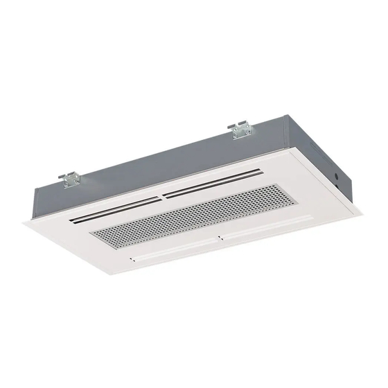
Brief description KaDeck are fan-operated ceiling cassettes for ceiling installation for the continuously variable air conditioning of all kinds of buildings and rooms that are to be heated or cooled silently. The units can be positioned at the wall or in the centre of the room and are available as dry or wet cooling models. -
Page 14: Installation And Wiring
KaDeck Assembly, installation and operating instructions Installation and wiring Defining the installation position The one-sided arrangement is installed on the The two-sided arrangement is installed in the centre window or corridor side. of the room. Isometrics – one-sided unit Isometrics – two-sided unit... -
Page 15: Minimum Clearances
Example of two-sided unit There needs to be a 5-fold minimum air exchange rate when heating with ceiling-mounted KaDeck units. Cold uninsulated floors can result in higher stratification of the room temperatures particularly in older buildings. Circulation may be required... -
Page 16: Installation
Consider the occupied zone when installing/suspending the units. Do not expose people to the direct air flow. Position the unit accordingly and adjust the air outlet if required. IMPORTANT NOTE! Sound insulation Provide for sound isolation between the KaDeck and the adjacent building if required. - Page 17 KaDeck Assembly, installation and operating instructions 6.4.1 Unit installation dimensions 1180 46.5 24.4 31.1 22.8 Fig. 3: Dimensions of one-sided unit 1180 46.5 24.4 31.1 22.8 Fig. 4: Dimensions of two-sided unit Art. no. System Grid dimen- Overall Overall width Water content –...
-
Page 18: Installing The Unit On The Ceiling
KaDeck Assembly, installation and operating instructions 6.4.2 Installing the unit on the ceiling 24.4 Drill four fixing holes (refer to drilling spacings) into the load-bearing ceil- 31.1 ing, insert dowels and fit the appropriate M8 threaded rods. Fig. 5: Drilling positions... -
Page 19: Installation
KaDeck Assembly, installation and operating instructions Release the design panel downwards. CAUTION: When opening/removing the design panel, do NOT allow the opening angle to exceed 90° to prevent dam- age! Fig. 9: Design panel open Unlock the hinges on the right and left by pulling on them and remove the design panel. -
Page 20: Connection Positions
KaDeck Assembly, installation and operating instructions 6.5.1 Connection positions 2-way valve and differential pressure- 2-way valve and differential pressure-independent independent valve up to 420 l, 2-pipe valve up to 420 l, 4-pipe Heating or cooling Heating and cooling Differential pressure-independent valve greater than 420 l,... -
Page 21: Connection To The Pipe Network
KaDeck Assembly, installation and operating instructions 6.5.2 Connection to the pipe network Isometrics, one-sided Isometrics, two-sided discharge discharge 1105 Side view, right Front view Side view, left Top view 1105 Rear view Fig. 13: Pipe connection dimensions Cooling supply (also heating with 2-pipe systems) -
Page 22: Primary Air Connection
Primary air spigots for the fresh air supply KaDeck units can be fitted with up to two primary air spigots. They enable pre-conditioned primary air to be fed into the Ka- Deck and the room. The conditioned air needs to be cleaned and fed into the room at a minimum temperature of 14 °C, and a maximum temperature of 25 °C. -
Page 23: Overview Of Valve Kits
Dimensions For use with Article no. [mm] Differential pres- 2-pipe, 24 V 2-point actuator KaDeck fan coils, cooling supply sure-independent 24 V Open/Closed, 50 Hz, sup- 180 x 30 x 523 326007110005 volume (min./max.) 200 - 1050 l/h plied separately... -
Page 24: Connecting The Supply Lines
[} 21] depending on the model (2-pipe / 4-pipe) and valve kit fitted (2-way pre-settable or differential pressure-independ- ent). Fig. 15: KaDeck without condensate tray Use a screwdriver to remove the plugs to open up the connection holes re- quired. - Page 25 KaDeck Assembly, installation and operating instructions Make sure that the insulation and corrugated pipes are not damaged. Push on the insulation as far as the thread of the corrugated pipes! Fig. 18: Insulation as far as the thread Place the actuator on the valve. Route the cable to the electrical connection box as per the diagram on the fan.
-
Page 26: Connecting The Primary Air Supply (Optional)
Fig. 22: Correct position of the condensate pump 6.5.6 Connecting the primary air supply (optional) If the KaDeck is to be supplied with primary air, remove the relevant spigot from the housing. Fig. 23: Removing the primary air spigot Apply silicone to the primary air connection spigot (optional accessory) to seal it. -
Page 27: Condensate Drainage Using A Condensate Pump
KaDeck Assembly, installation and operating instructions 6.5.7 Condensate drainage using a condensate pump Condensate is only drained by a condensate pump with "wet cooling" versions. The water is drawn off by the condensate pump and discharged along a hose (supplied loose) connected on the pressure side. -
Page 28: Dewpoint Monitor
KaDeck Assembly, installation and operating instructions 6.5.8 Dewpoint monitor A dewpoint monitor can optionally be fitted with dry cooling units. It measures the relative humidity directly on the surface of the cooled part of the system and so can prevent further condensate formation should the temperature fall below the dew- point. -
Page 29: Electrical Connection
3261xxx11x 0.13 IP20 3261xxx61x 0.20 IP20 3261xxx12x 0.22 IP20 3261xxx62x 0.29 IP20 Tab. 6: Maximum electrical rating values KaDeck KaDeck, KaControl version (*C1) Article Nominal voltage [V Mains fre- Nominal power Nominal Ri analogue IP class Protection number quency [Hz] current input [kΩ]... -
Page 30: Electromechanical Control
KaDeck Assembly, installation and operating instructions Electromechanical control 7.2.1 Connection (*00) Electrical junction box Position of electrical junction box (with condensate tray removed) Use a Phillips screwdriver to open the electrical junction box and remove the cover of the junction box. - Page 31 KaDeck Assembly, installation and operating instructions Circuit description Factory-fitted actuators are wired to the terminals on the control board. If no valve actuators are factory-fitted, appropri- ate terminals are available for on-site valve actuators. Only 24 V DC valve actuators (Open/Closed or continuous) can be connected.
- Page 32 KaDeck Assembly, installation and operating instructions Section of circuit board Description Terminal block X5 (valve 1 connection): Valve actuator V1 24 V DC Open/Closed or continuous valves With 2-pipe versions: Heating/cooling valve With 4-pipe versions: Cooling valve Terminal block X6 (valve 2 connection):...
- Page 33 KaDeck Assembly, installation and operating instructions Refer to these points in the following layout plans with electromechanical control: Comply with the details on cable types and cabling with due consideration of VDE 0100. Without *: NYM-J. The requisite number of wires, including PE conductor, is stated on the cable. Cross-sections are not stated, as the cable length is involved in the calculation of the cross-section.
-
Page 34: Vp_326_Kadeck-Epp_00_30155.Pdf
230 V electromechanical, 2- or 4-pipe valve actuator(s) 24 V DC Open/Closed, optional condensate pump, with room thermostat type 30155... -
Page 35: Vp_326_Kadeck-Epp_00_30256_2Leiter.pdf
KaDeck EPP, electromechanical, 2-pipe, valve actuator 24 V DC Open/Closed, optional condensate pump, with clock thermostat type 30256... -
Page 36: Vp_326_Kadeck-Epp_00_30256_4Leiter.pdf
PPE KaDeck, électromécanique, 4 conduites, actionneur de vanne 24 V DC ouvert/fermé, pompe d’eau de condensation en option, avec thermostat programmable type 30256... -
Page 37: Vp_326_Kadeck-Epp_00_Glt.pdf
KaDeck EPP, 230 V electromechanical, 2- or 4-pipe, valve actuator(s) 24 V DC Open/Closed, optional condensate pump, 0-10 V DC control via BAS... -
Page 38: Vp_326_Kadeck-Epp_00-14894X.pdf
KaDeck EPP, 230 V electromechanical, 2- or 4-pipe, valve actuator(s) 24 V DC Open/Closed, optional condensate pump, with Climate Controller type 14894x... -
Page 39: Kacontrol (*C1)
KaDeck Assembly, installation and operating instructions KaControl (*C1) 7.3.1 KaController installation Fig. 28: Installation of flush-mounted back box Electrical connection Connect the KaController to the nearest KaControl unit in line with the wiring diagram. The maximum bus length between the KaController and the KaControl master unit is 30 m. -
Page 40: Connection (*C1)
KaDeck Assembly, installation and operating instructions 7.3.2 Connection (*C1) General information Route all low voltage cables along the shortest route. Ensure that low-voltage and power cables are separated, using metal partitions on cable harnesses. Wrong! Use only shielded cables as low-voltage and bus cables. - Page 41 KaDeck Assembly, installation and operating instructions IMPORTANT NOTE! Use shielded, paired cables as bus cables, UNITRONIC® BUS LD 2x2x0.22, but at least of the same value or higher. IMPORTANT NOTE! When laying bus cables, avoid the formation of star points, for instance in junction boxes. Loop the cables...
- Page 42 KaDeck Assembly, installation and operating instructions Circuit description Units configured for operation with KaControl are fully wired and fitted with all electrical parts ready for connection (with the exception of optional accessories). The speed of the EC fans used is controlled by a 0-10 V DC signal with KaControl. The "intelligent" motor electronics de- tect any possible motor malfunction and automatically switch off the fan.
- Page 43 KaDeck Assembly, installation and operating instructions Section of circuit board Description Terminal block X6 (valve 2 connection): Valve actuator V2 24 V DC Open/Closed valves With 4-pipe versions: Valve, heating Note: With 2-pipe versions: parametrisable potentially loaded collect- ive fault signal 24 V DC 0.5 A (see smartboard instructions)
- Page 44 KaDeck Assembly, installation and operating instructions Observe these points in the following layout plans with KaControl: Comply with the details on cable types and cabling with due consideration of VDE 0100. Without *: NYM-J. The requisite number of wires, including PE conductor, is stated on the cable. Cross-sections are not stated, as the cable length is involved in the calculation of the cross-section.
- Page 45 KaDeck EPP, KaControl C1, 2- or 4-pipe, valve actuator(s) 24 V DC Open/Closed, 0-10 V DC control via BAS...
- Page 46 KaDeck EPP, KaControl C1, 2- or 4-pipe, valve actuator(s) 24 V DC Open/Closed, with KaController type 321000x...
-
Page 47: Pre-Commissioning Checks
KaDeck Assembly, installation and operating instructions Pre-commissioning checks Before initial commissioning, check whether all the necessary conditions have been met so that the unit can function safely and properly. Structural tests Check that the unit is securely standing and fixed. -
Page 48: Operation
KaDeck Assembly, installation and operating instructions Operation Operation of electromechanical control Room thermostat, type 30155 Electronic room thermostat with 3-stage automatic function for 2- and 4- pipe applications, surface-mounted wall installation on a flush-mounted box in visually unobtrusive design simple operation using a large rotary dial for temperature setting with... - Page 49 KaDeck Assembly, installation and operating instructions Climate controller, white, type 196000148941 for 2- and 4-pipe applications, surface-mounted wall installation on a flush- mounted box with a visually unobtrusive design with 2.5” LCD display and high-quality glass finish with capacitive keys...
- Page 50 KaDeck Assembly, installation and operating instructions Climate controller, white, type 196000148943 with Modbus interface for 2- and 4-pipe applications, surface-mounted wall installation on a flush- mounted box with a visually unobtrusive design with 2.5” LCD display and high-quality glass finish with capacitive keys...
-
Page 51: Operation Of The Kacontroller
KaDeck Assembly, installation and operating instructions Operation of the KaController The following information is limited to the key content on the operation of the KaController and KaControl system. More in- formation is included separately in the KaControl SmartBoard user manual. - Page 52 KaDeck Assembly, installation and operating instructions KaController without operating keys (one-button operation) type 3210001 1. Display with LED background lighting 2. Navigator dial Change settings Call up menus Fig. 38: KaController type 3210001 KaController, black without function keys (one-button opera- tion) type 3210006 1.
-
Page 53: Maintenance
KaDeck Assembly, installation and operating instructions Maintenance 10.1 Securing against reconnection DANGER! Risk of death by unauthorised or uncontrolled restart! Unauthorised or uncontrolled restarting of the equipment can result in serious injury or death. Before restarting, ensure that all safety devices are fitted and working properly and that there is no haz- ard to humans. -
Page 54: Maintenance Schedule
KaDeck Assembly, installation and operating instructions 10.2 Maintenance Schedule: The sections below describe maintenance work needed for the proper and trouble-free operation of the equipment. If there are signs of increased wear during regular checks, shorten the required maintenance intervals to the actual wear and teat. -
Page 55: Replacing The Filter
KaDeck Assembly, installation and operating instructions 10.3.1 Replacing the filter. CAUTION! Risk of injury from sharp metal housing! The inner metal of the casing can have sharp edges. Wear suitable protective gloves. Fig. 41: Remove the filter. Fig. 42: Vacuum the filter and re-fit it after cleaning. -
Page 56: Cleaning The Condensate Pump
KaDeck Assembly, installation and operating instructions Clean the condensate tray. 10.3.3 Cleaning the condensate pump Remove the hose from the condensate pump and remove the condensate pump to clean it. Fig. 43: Dismantling the condensate pump Carefully clean the filling level monitor with a damp cloth. Make sure that the contacts do not bend when cleaning them! Fig. 44: Cleaning the condensate pump... -
Page 57: Clean The Inside Of The Unit
KaDeck Assembly, installation and operating instructions 10.3.4 Clean the inside of the unit Check all elements that come into contact with air (internal surfaces of the unit, outlet elements etc.) for dirt or deposits dur- ing maintenance and use a commercially available product to remove. -
Page 58: Faults
KaDeck Assembly, installation and operating instructions Faults The following chapter describes possible causes of faults and the work needed to rectify them. Should faults occur frequently, shorten the maintenance intervals in line with the actual loading on the unit. Contact the manufacturer with any faults that cannot be rectified using the following informatio. -
Page 59: Kacontrol Faults
KaDeck Assembly, installation and operating instructions Fault Possible cause Remedy Clean and/or replace impeller. Please make sure Rotating parts unbalanced that no balancing clips are removed during cleaning. Fan dirty. Clean dirt from fan. Heat exchanger dirty. Clean dirt from Heat exchanger. -
Page 60: List Of Kacontrol Parameters
P030 Ventilation temperature activation °C P031 Ventilation interval °C P032 Rinsing function: maximum idle time of fan P033 Rinsing function: duration of the rinsing function P034 Rinsing function: activation in operating modes Parameter key KaDeck, SAP no. 9001389, dated 10.07.2020... - Page 61 KaDeck Assembly, installation and operating instructions Parameter Function Standard Min. Max. Unit KaDeck Fan run-on time after an operating mode is switched to P035 stage 1 P036 Type of setpoint setting P037 Display P038 Lock/disable function on the control unit...
- Page 62 KaDeck Assembly, installation and operating instructions Parameter Function Standard Min. Max. Unit KaDeck P076 Serial address of slave 6 P077 Serial address of slave 7 P078 Serial address of slave 8 P079 Serial address of slave 9 P080 Serial address of slave 10...
- Page 63 KaDeck Assembly, installation and operating instructions Parameter Function Standard Min. Max. Unit KaDeck P119 Off delay time P120 reserved P121 reserved P122 Relative fan speed increase via contact P123 Maximum valve running time Minimum P + I output variation for valve movement (0 to...
-
Page 64: Kacontroller Parameter List
KaDeck Assembly, installation and operating instructions 12.2 KaController parameter list Para- Function Standard Min. Max. Unit Comment meter Address in Mod- t001 Serial address bus network Baud rate 0 = Baud rate 4800 t002 1 = Baud rate 9600 2 = Baud rate 19200... -
Page 65: Certificates
KaDeck Assembly, installation and operating instructions Certificates... -
Page 66: 326_Eu_Konformitätserklärung_Kadeck.pdf
że produkt: deklarujeme, vědomi si své odpovědnosti, že produkt: Type, Modell, Artikel-Nr.: KaDeck 326*** Type, Model, Articles No.: Type, Modèle, N° d’article: Typ, Model, Nr artykułu: Typ, Model, Číslo výrobku:... - Page 67 Conformément aux dispositions de Directive: Zgodnie z postanowieniami Dyrektywy: Odpovídající ustanovení směrnic: 2014/30/EU EMV-Richtlinie 2014/35/EU Niederspannungsrichtlinie Hendrik Kampmann Lingen (Ems), den 01.09.2020 ___________________________________ Ort und Datum der Ausstellung Name und Unterschrift des Befugten Place and Date of Issue Name and Signature of authorized person Lieu et date d’établissement...
- Page 68 Operating voltage ..............................7 Tab. 3 Water quality................................7 Tab. 4 Overview of valve kits ............................23 Tab. 5 KaDeck valve installation ............................23 Tab. 6 Maximum electrical rating values ......................... 29 Tab. 7 Maximum electrical rating values ......................... 29 Tab. 8 Description of control board (*00) .........................
- Page 72 Land Kontakt Country Contact Kampmann GmbH & Co. KG Kampmann UK Ltd. Friedrich-Ebert-Str. 128 - 130 Dial House, Govett Avenue 49811 Lingen (Ems) Shepperton, Middlesex, TW17 8AG T +49 591/ 7108-660 T +44 1932/ 228592 Germany Great Britain...
Need help?
Do you have a question about the KaDeck and is the answer not in the manual?
Questions and answers