
Related Manuals for Kampmann KaCool D HC


Summary of Contents for Kampmann KaCool D HC
- Page 1 KaCool D HC ► Assembly, installation and operating instructions Keep these instructions in a safe place for future use! Issue06/21EN SAP No.1456278...
-
Page 3: Table Of Contents
Table of contents 1 General ..........................5 1.1 About these instructions ......................... 1.2 Explanation of Symbols........................... 2 Safety............................ 6 2.1 Correct use.............................. 2.2 Limits of operation and use ........................2.3 Risk from electrocution!.......................... 2.4 Personnel requirements - Qualifications ....................2.5 Personal Protective Equipment ....................... 3 Transport, storage and packaging.................. - Page 4 7.2.1 Connection (*00)............................26 7.2.2 Cable laying, KaCool D HC (**00)......................27 8 Pre-commissioning checks ....................30 9 Operation..........................31 9.1 Operation of electromechanical control ....................31 10 Maintenance ......................... 33 10.1 Securing against reconnection ........................ 33 10.2 Maintenance Schedule:........................... 33 10.3 Maintenance work..........................
-
Page 5: General
KaCool D HC Assembly, installation and operating instructions General About these instructions These instructions ensure the safe and efficient handling of this equipment. These instructions form an integral part of the equipment and have to be kept in the direct vicinity of the equipment and available to personnel at all times. -
Page 6: Safety
KaCool D HC Assembly, installation and operating instructions Safety This section provides an overview of all important safety aspects to ensure optimum protection of personnel as well as safe and trouble-free operation. In addition to the safety instructions in these operating instructions, the valid safety, accident pre- vention and environmental protection regulations must be observed for the area of use of the unit. - Page 7 KaCool D HC Assembly, installation and operating instructions Limits of operation and use Limits of operation Min./max. water temperature °C 4-90 Min./max. air intake temperature °C 6--40 Min./max. air humidity 20-60 Min. operating pressure bar/kPa Max. operating pressure bar/kPa 10/1000 Min./max.
-
Page 8: Risk From Electrocution
KaCool D HC Assembly, installation and operating instructions IMPORTANT NOTE! Danger of frost in cooling mode! There is a risk of the heat exchanger freezing when used in unheated rooms. Make sure that the unit is equipped with a frost protection sensor and/or thermostat in this case. -
Page 9: Personnel Requirements - Qualifications
KaCool D HC Assembly, installation and operating instructions Personnel requirements - Qualifications Expertise The installation of this product requires specialist knowledge of heating, cooling, ventilation, installation and electrical engin- eering. This knowledge, generally learned in professional training in one of the fields mentioned above, is not described sep- arately. -
Page 10: Transport, Storage And Packaging
IMPORTANT NOTE! Warranty claims can only be made within the applicable period for complaints. (More information is avail- able in the T&Cs on the Kampmann website) IMPORTANT NOTE! 2 people are needed to transport the unit. Wear personal protective clothing when transporting the unit. -
Page 11: Storage
KaCool D HC Assembly, installation and operating instructions Storage Store packaging under the following conditions: Do not store outdoors. Store in a dry and dust-free place. Store in a frost-free place. Do not expose to aggressive media. Protect from direct sunlight. -
Page 12: Technical Data
KaCool D HC Assembly, installation and operating instructions Technical data Unit KaCool D HC Model Width of basic unit [mm] Panel width [mm] Length of basic unit (car- 1250 cass) [mm] Panel length [mm] 1180 Height of basic unit, com-... -
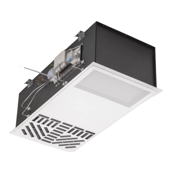
Page 13: Construction And Function
KaCool D HC Assembly, installation and operating instructions Construction and function Overview Fig. 1: KaCool D HC at a glance Air vents Water connections Actuator Electrical junction box Heat exchanger EC radial fan Filter cassette epm1, 85 % Condensate tray Float switch... -
Page 14: Brief Description
Brief description KaCool D HC are decentralised units for the heating, cooling and filtering of room air, specifically developed for use in clean rooms in the healthcare sector (hospitals, medical surgeries etc.) in compliance with the Hygiene Standard 1946-4. Secondary air is drawn in by the fan through an ePM1>55 % filter and is passed through the copper/aluminium heat exchanger. -
Page 15: Installation And Wiring
KaCool D HC Assembly, installation and operating instructions Installation and wiring Definition of the connection side Front view Side view Fig. 2: Water connection position Supply ½“ Return ½“ Requirements governing the installation site Only install and assemble the unit if the following conditions are met: Make sure that the ceiling is sufficiently load-bearing to take the weight of the unit (Technical data [} 12]). -
Page 16: Minimum Clearances
KaCool D HC Assembly, installation and operating instructions Minimum clearances > 1400 mm > 1400 mm > 4000 mm > 55.118 Inch > 55.118 Inch > 157.48 Inch min. 920* mm min. 400* mm min. 36.2* Inch min. 15.7* Inch... -
Page 17: Installation
Consider the occupied zone when installing/suspending the units. Do not expose people to the direct air flow. Position the unit accordingly and adjust the air outlet if required. IMPORTANT NOTE! Sound insulation Provide for sound isolation between the KaCool D HC and the adjacent building if required. - Page 18 KaCool D HC Assembly, installation and operating instructions 6.4.1 Installation of basic unit 26.5 Front view Left side view Plan view Fig. 5: Suspension points, inch Front view Left side view Plan view Fig. 6: Suspension points, mm Note the Venkon minimum clearances when installing the basic units! Mark the dimensions and distances of the key holes on the wall or ceiling as per the drawing, drill the holes and use ap- propriate fixing materials to install the basic unit.
-
Page 19: Installation
“Wet cooling” operating mode only when the fan is switched on Only operate KaCool D HC with “wet cooling” mode (supply temperature below 15 °C) when the fan is switched on, as otherwise condensate can be produced on the outlet panel, which could then drip down. -
Page 20: Connection To The Pipe Network
KaCool D HC Assembly, installation and operating instructions 6.5.1 Connection to the pipe network The supply and return connections are located as standard on the left side of the unit seen in the direction of air flow. Route the pipework so that no mechanical stresses are transferred to the heat exchanger and to ensure that the unit can be accessed with ease for maintenance and repair work. -
Page 21: Connection Of 2-Way Valve Kit
KaCool D HC Assembly, installation and operating instructions 6.5.2 Connection of 2-way valve kit Fig. 8: Dimensions in mm Fig. 9: Dimensions in inches Return ½“ Supply ½“ Supply vent Return vent... -
Page 22: Insulating The Pipework
KaCool D HC Assembly, installation and operating instructions 6.5.3 Insulating the pipework Apply adhesive to the front cross-section of the diffusion-tight insulation (by others). Push the diffusion-tight insulation (by others) along the pipes as far as the wall of the housing and press it to produce an adhesive joint. - Page 23 KaCool D HC Assembly, installation and operating instructions 6.5.4.2 Condensate drainage using a condensate pump (accessory) The water is drawn off by the condensate pump and discharged along a hose (supplied loose) connected on the pressure side. Depending on conditions on site, the water can be discharged into drainage lines, possibly with a trap connection.
- Page 24 KaCool D HC Assembly, installation and operating instructions Connecting the condensate pump Push the suction hose as far as it will go and fix in place with a cable tie to prevent the pump from running dry. Connect the hose to the condensate drain (separate). Direction of flow: refer to the arrow on the side of the housing Max.
-
Page 25: Differential Pressure Switch
KaCool D HC Assembly, installation and operating instructions 6.5.5 Differential pressure switch Differential pressure switch Two differential pressure switches are factory-fitted on the unit. They are used to evaluate the condition of the intake and discharge filter. Before commissioning, set the required final pressure differences according to the table below. -
Page 26: Electrical Connection
Condensation formation in the cooling unit! In the event of on-site valve control, the cooling valve must be closed when the fans are switched off. Maximum electrical rating values KaCool D HC , electromechanical design (*00), F7/ F9 filter Size Nominal... - Page 27 0 - 10 V DC - Condensate alarm Note these points in the following layout plans for KaCool D HC: Comply with the details on cable types and cabling with due consideration of VDE 0100. Without *: NYM-J. The requisite number of wires, including PE conductor, is stated on the cable. Cross-sections are not stated, as the cable length is involved in the calculation of the cross-section.
-
Page 28: Cable Laying, Kacool D Hc (**00)
KaCool D HC Assembly, installation and operating instructions 7.2.2 Cable laying, KaCool D HC (**00) Cable laying with KaCool DHC (*00), control by Climate Controller, type 14894x... - Page 29 KaCool D HC Assembly, installation and operating instructions Cable laying with KaCool DHC (*00), control by DDC/BMS...
-
Page 30: Pre-Commissioning Checks
KaCool D HC Assembly, installation and operating instructions Pre-commissioning checks Check before initial commissioning whether all necessary conditions have been met so that the unit can function safely and properly. Structural tests Check that the unit is securely standing and fixed. -
Page 31: Operation
KaCool D HC Assembly, installation and operating instructions Operation Operation of electromechanical control Climate controller, white, type 196000148941 For 2- and 4-pipe applications, surface-mounted wall mounting on a flush- mounted box in visually unobtrusive design with 2.5” :CD display and high-... - Page 32 KaCool D HC Assembly, installation and operating instructions Climate controller, white, type 196000148943 With Modbus interface For 2- and 4-pipe applications, surface-mounted wall mounting on a flush- mounted box in visually unobtrusive design with 2.5” :CD display and high- quality glass finish with capacitive keys...
-
Page 33: Maintenance
KaCool D HC Assembly, installation and operating instructions Maintenance 10.1 Securing against reconnection DANGER! Risk of death by unauthorised or uncontrolled restart! Unauthorised or uncontrolled restarting of the equipment can result in serious injury or death. Before restarting, ensure that all safety devices are fitted and working properly and that there is no haz- ard to humans. -
Page 34: Maintenance Work
KaCool D HC Assembly, installation and operating instructions 10.3 Maintenance work Dismantle the service hatch before maintenance work! Remove the service hatch before all visual inspections and maintenance work to access the basic unit. 10.3.1 Opening the inspection flap Carefully pull the revision flap down until it comes to a stop and is held by the retaining cable. -
Page 35: Visual Checks
KaCool D HC Assembly, installation and operating instructions 10.3.3 Visual checks Remove the internal panels. Dismantle the inspection cover and the air baffle as follows for visual inspections after the revision flap has been opened. Unscrew the wing bolts on the inspection cover. -
Page 36: Cleaning The Condensate Tray
KaCool D HC Assembly, installation and operating instructions Fig. 23: Internal view of the unit (panels removed) Check all elements that come into contact with air (internal surfaces of the unit, air discharge elements etc.) for soiling or deposits during maintenance and use a commercially available product to remove. -
Page 37: Cleaning The Float Switch
KaCool D HC Assembly, installation and operating instructions 10.3.5 Cleaning the float switch Loosen the wing bolt. Remove the retaining panel with the float switch fitted. Fig. 26: Open the cover of the float switch. Fig. 27: Clean the float switch. Fig. 28: 10.3.6 Clean the inside of the unit... -
Page 38: Faults
KaCool D HC Assembly, installation and operating instructions Faults The following chapter describes possible causes of faults and the work needed to rectify them. Should faults occur frequently, shorten the maintenance intervals in line with the actual loading on the unit. -
Page 39: Start-Up After Rectification Of Fault
KaCool D HC Assembly, installation and operating instructions Fault Possible cause Remedy Clean and/or replace impeller. Please make sure Rotating parts unbalanced that no balancing clips are removed during cleaning. Fan dirty. Clean dirt from fan. Heat exchanger dirty. Clean dirt from Heat exchanger. -
Page 40: Certificates
KaCool D HC Assembly, installation and operating instructions Certificates EU-Konformitätserklärung EU Declaration of Conformity Déclaration de Conformité CE Deklaracja zgodności CE EU prohlášení o konformite KAMPMANN Wir (Name des Anbieters, Anschrift): GMBH & Co. KG Friedrich-Ebert-Str. 128-130 We (Supplier’s Name, Address):... - Page 41 KaCool D HC Assembly, installation and operating instructions DIN EN 61000-6-1; -6-2; -6-3 Elektromagnetische Verträglichkeit DIN EN 60335-1; -2-40 Sicherheit elektr. Geräte f. den Hausgebrauch und ähnliche Zwecke Gemäß den Bestimmungen der Richtlinien: Following the provisions of Directive: Conformément aux dispositions de Directive: Zgodnie z postanowieniami Dyrektywy: Odpovídající...
- Page 42 KaCool D HC Assembly, installation and operating instructions...
-
Page 43: Table
KaCool D HC Assembly, installation and operating instructions Table Tab. 1 Limits of operation..............................7 Tab. 2 Operating voltage..............................7 Tab. 3 Water quality ................................7 Tab. 4 Technical data, condensate pump .......................... 24 Tab. 5 Filter pressure losses............................... 25 Tab. - Page 44 Land Kontakt Country Contact Kampmann GmbH & Co. KG Kampmann UK Ltd. Friedrich-Ebert-Str. 128 - 130 Dial House, Govett Avenue 49811 Lingen (Ems) Shepperton, Middlesex, TW17 8AG T +49 591/ 7108-660 T +44 1932/ 228592 Germany Great Britain F +49 591/ 7108-173 F +44 1932/ 228949 E export@kampmann.de...
Need help?
Do you have a question about the KaCool D HC and is the answer not in the manual?
Questions and answers