
Subscribe to Our Youtube Channel
Related Manuals for Kampmann PowerKon LT


Summary of Contents for Kampmann PowerKon LT
- Page 1 PowerKon LT ► Assembly, installation and operating instructions Keep these instructions in a safe place for future use! Issue07/23EN SAP No.1816160...
-
Page 3: Table Of Contents
6.3 Minimum clearances..........................15 6.4 Installation............................. 15 6.4.1 Installing the unit ............................16 6.4.2 Replacing heaters / conversion to PowerKon LT ..................18 6.5 Installation............................. 20 6.5.1 Connection to the pipe network ........................ 21 6.5.2 Overview of valve kits ..........................21 6.5.3... - Page 4 7.4 Connection display control (*N2)......................34 8 Pre-commissioning checks....................38 9 Operation..........................39 9.1 Operation of electromechanical control ....................39 9.2 Display control ............................39 10 Maintenance ......................... 42 10.1 Securing against reconnection ....................... 42 10.2 Maintenance Schedule:.......................... 42 10.3 Maintenance work ..........................43 10.3.1 Clean the inside of the unit ........................
-
Page 5: General
PowerKon LT PowerKon LT Assembly, installation and operating instructions General About these instructions These instructions ensure the safe and efficient handling of this equipment. These instructions form an integral part of the equipment and have to be kept in the direct vicinity of the equipment and available to personnel at all times. -
Page 6: Safety
PowerKon LT PowerKon LT Assembly, installation and operating instructions Safety This section provides an overview of all important safety aspects to ensure optimum protection of personnel as well as safe and trouble-free operation. In addition to the safety instructions in these operating instructions, the valid safety, accident pre- vention and environmental protection regulations must be observed for the area of use of the unit. - Page 7 PowerKon LT PowerKon LT Assembly, installation and operating instructions Limits of operation and use Limits of operation Min./max. water temperature °C 5-80 Min./max. air intake temperature °C 6-40 Min./max. air humidity 20-60 Min. operating pressure bar/kPa Max. operating pressure bar/kPa 16/1600 Min./max.
-
Page 8: Risk From Electrocution
PowerKon LT PowerKon LT Assembly, installation and operating instructions IMPORTANT NOTE! Danger of frost in cooling mode! There is a risk of the heat exchanger freezing when used in unheated rooms. Make sure that the unit is equipped with a frost protection sensor and/or thermostat in this case. -
Page 9: Personnel Requirements - Qualifications
PowerKon LT PowerKon LT Assembly, installation and operating instructions Personnel requirements - Qualifications Expertise The installation of this product requires specialist knowledge of heating, cooling, ventilation, installation and electrical engin- eering. This knowledge, generally learned in professional training in one of the fields mentioned above, is not described sep- arately. -
Page 10: Transport, Storage And Packaging
IMPORTANT NOTE! Warranty claims can only be made within the applicable period for complaints. (More information is avail- able in the T&Cs on the Kampmann website) IMPORTANT NOTE! 2 people are needed to transport the unit. Wear personal protective clothing when transporting the unit. -
Page 11: Storage
PowerKon LT PowerKon LT Assembly, installation and operating instructions Storage Store packaging under the following conditions: Do not store outdoors. Store in a dry and dust-free place. Store in a frost-free place. Do not expose to aggressive media. Protect from direct sunlight. -
Page 12: Technical Data
998 - 1974 1209 - 2485 Sound power level [dB(A)] 28 - 48 28 - 48 28 - 48 Tab. 4: Technical data, PowerKon LT at LPHW 45/40°C, t = 20°C at CHW 7/12°C, t = 27 °C, 48% relative humidity... -
Page 13: Construction And Function
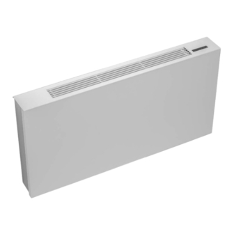
Electrical junction box Brief description PowerKon LT are fan-assisted and wall-mounted convectors/heaters for heating and cooling. The units silently air condition rooms and their multiple connection options make them suitable for use in new as well as existing buildings. Wear parts list... -
Page 14: Installation And Wiring
Definition of the connection side RHS connection LHS connection Fig. 2: Definition of the PowerKon LT connection side Requirements governing the installation site Only install and assemble the unit if the following conditions are met: Ensure that the unit is securely suspended. -
Page 15: Minimum Clearances
>100 >100 Fig. 3: PowerKon LT minimum clearances This area needs to be kept as free as possible to ensure that the air can flow freely out of the air outlet grille. Window sills should be a minimum of 10 cm from the air outlet and should not protrude more than 12 cm into the room. It could affect the... -
Page 16: Installation
Consider the occupied zone when installing/suspending the units. Do not expose people to the direct air flow. Position the unit accordingly and adjust the air outlet if required. IMPORTANT NOTE! Sound insulation Provide for sound isolation between the PowerKon LT and the adjacent building if required. - Page 17 PowerKon LT PowerKon LT Assembly, installation and operating instructions 6.4.1 Installing the unit...
- Page 18 PowerKon LT PowerKon LT Assembly, installation and operating instructions 780 / 1030 / 1220 Fig. 4: PowerKon LT dimensions...
-
Page 19: Replacing Heaters / Conversion To Powerkon Lt
Loosen the thermostatic valve and return shut-off valve. Remove the heater and dismantle the existing fitting from the wall. Position the fixing rail for PowerKon LT, level and fix in place. Prepare the existing pipework for water-side connection. Suspend the functional unit and make sure that it is seated correctly in the... -
Page 20: Installation
Connect the water-side lines. (Electrical connection on the opposite side of the unit) Connect the functional unit’s earthing cable to the casing. Attach the casing of the PowerKon LT. Installation Actuator with ‘First Open’ function When delivered, the actuator is normally open in a de-energised state, thanks to the First Open function. This enables heating mode to run even if the electric wiring is not yet completed. -
Page 21: Connection To The Pipe Network
Use appropriate insulating material, and impermeable insulating material for cooling units. Tighten all threaded connections once the pipes have been fitted and check that they are not under any tension. 780 / 1030 / 1220 Fig. 6: PowerKon LT connection dimensions RHS connection LHS connection... -
Page 22: Overview Of Valve Kits
Assembly, installation and operating instructions 6.5.2 Overview of valve kits Valve kits 2-pipe, includes pre-set- table valve, angled return shut-off valve, with 2x PowerKon LT, DN 15 129012100201 stainless steel corrugated pipes, 1/2” connection on left, KVS value 1.7 m³/h Pre-adjustable thermostatic... -
Page 23: Condensation Connection
PowerKon LT PowerKon LT Assembly, installation and operating instructions 6.5.3 Condensation connection 6.5.3.1 Condensation drain with natural gradient Optional “Cooling accessory kit, connection on left and right” Figure Article Properties For use with Art. no. Accessory kit for cooling with condensate for con-... - Page 24 Installation, cabling of the condensate pump (accessory) The condensate pump needs a 230 V/50 Hz power supply. It can be connected via the terminals of the PowerKon LT. Depend- ing on the control version, the alarm contact can be connected to auxiliary terminals or directly to the circuit board. Appropri-...
- Page 25 PowerKon LT PowerKon LT Assembly, installation and operating instructions Figure Article Description Article no. Condensate pump for cooling below the dew point, for the discharge of condensate pro- Condensate pump set (sup- duced, 50 - 60 Hz, consisting of valve con-...
- Page 26 PowerKon LT PowerKon LT Assembly, installation and operating instructions Technical data Maximum flow volume 42 l/hour (11 gph) Maximum delivery height 20 m (65.60 ft.) Maximum horizontal delivery volume 100 m (330 ft.) at 0 m delivery height and 0 m suction height...
- Page 27 PowerKon LT PowerKon LT Assembly, installation and operating instructions Condensate pump alarm messages LED alarm relay signals LED alarm relay operating table Starting sequence (normally closed) (normally open) Pump status Condensate level Standard mode Peripheral mode Not driven Driven Below the alarm stage...
-
Page 28: Electrical Connection
0.23 IP21 34.8 0.30 IP21 Tab. 7: Maximum electrical rating values PowerKon LT Electromechanical connection, 230 V (*00) Circuit description (*00) Factory-fitted actuators are wired to the terminals. The appropriate terminals are available for valve actuators or a condensate pump. The EC fans used can be continuously variably controlled by a 0-10 V DC signal. The “intelligent” motor electronics de- tects any possible motor malfunction and automatically switches off the fan. - Page 29 PowerKon LT PowerKon LT Assembly, installation and operating instructions...
- Page 30 PowerKon LT PowerKon LT Assembly, installation and operating instructions...
- Page 31 PowerKon LT PowerKon LT Assembly, installation and operating instructions...
- Page 32 PowerKon LT PowerKon LT Assembly, installation and operating instructions...
-
Page 33: Connection Of Thermostatic Head Control (*N1)
PowerKon LT PowerKon LT Assembly, installation and operating instructions Connection of thermostatic head control (*N1) Circuit description (*N1) Units with thermostatic head control are fully wired and supplied ex-works with all electrical components and a connec- tion cable with a standard European plug. -
Page 34: Connection Display Control (*N2)
PowerKon LT PowerKon LT Assembly, installation and operating instructions Connection display control (*N2) Circuit description (*N2) Units with display control are fully wired and supplied ex-works with all electrical components and a connection cable with a standard European plug. Power supply 230 V... - Page 35 PowerKon LT PowerKon LT Assembly, installation and operating instructions Function Standard System 4-pipe 2-pipe Heating valve outlet Heating Operation Touch display Motor type 0-10 V DC Cooling fan operation Thermostatic control Permanently on Heating fan operation Thermostatic control Permanently on...
- Page 36 PowerKon LT PowerKon LT Assembly, installation and operating instructions...
- Page 37 PowerKon LT PowerKon LT Assembly, installation and operating instructions...
-
Page 38: Pre-Commissioning Checks
PowerKon LT PowerKon LT Assembly, installation and operating instructions Pre-commissioning checks When commissioning the device for the first time, ensure that all the necessary requirements are met so that the device can function safely and in accordance with its intended use. -
Page 39: Operation
PowerKon LT PowerKon LT Assembly, installation and operating instructions Operation Operation of electromechanical control Room thermostat, type 30155 Electronic room thermostat with 3-stage automatic function for 2- and 4- pipe applications, surface-mounted wall installation on a flush-mounted box in visually unobtrusive design... -
Page 40: Display Control
PowerKon LT PowerKon LT Assembly, installation and operating instructions Display control Every time the power supply is switched on, the display shows “---” for 10 seconds (start mode). Then it returns to the oper- ating mode last selected. The backlight is automatically switched off 30 seconds after the last operation on the display. The three brightness levels of the backlight can be permanently activated using a parameter setting. - Page 41 PowerKon LT PowerKon LT Assembly, installation and operating instructions User parameters Parameter Description Setting Standard Display brightness 3-2-1-Off Operating mode Aut-HEA-COO Celsius or Fahrenheit Quit menu Yes-No Password for extended access -99-999 Off = display is automatically switched off 30 seconds after the last operation.
-
Page 42: Maintenance
PowerKon LT PowerKon LT Assembly, installation and operating instructions Maintenance 10.1 Securing against reconnection DANGER! Risk of death by unauthorised or uncontrolled restart! Unauthorised or uncontrolled restarting of the equipment can result in serious injury or death. Before restarting, ensure that all safety devices are fitted and working properly and that there is no haz- ard to humans. -
Page 43: Maintenance Work
PowerKon LT PowerKon LT Assembly, installation and operating instructions 10.3 Maintenance work 10.3.1 Clean the inside of the unit Check all elements that come into contact with air (internal surfaces of the unit, outlet elements etc.) for dirt or deposits dur- ing maintenance and use a commercially available product to remove. -
Page 44: Cleaning The Condensate Tray
PowerKon LT PowerKon LT Assembly, installation and operating instructions 10.3.3 Cleaning the condensate tray Clean the condensate tray. 10.3.4 Cleaning the valve condensation tray Clean the valve condensate tray. -
Page 45: Faults
PowerKon LT PowerKon LT Assembly, installation and operating instructions Faults The following chapter describes possible causes of faults and the work needed to rectify them. Should faults occur frequently, shorten the maintenance intervals in line with the actual loading on the unit. -
Page 46: Start-Up After Rectification Of Fault
PowerKon LT PowerKon LT Assembly, installation and operating instructions 11.1 Fault table Fault Possible cause Remedy Check voltage, switch on repair switch. No function. No power supply. Replace fuse. Heat exchanger defect. Replace heat exchanger if necessary. System water leakage Hydraulic connection not correct. -
Page 47: Certificates
PowerKon LT PowerKon LT Assembly, installation and operating instructions Certificates EU-Konformitätserklärung EU Declaration of Conformity Déclaration de Conformité CE Deklaracja zgodności CE EU prohlášení o konformite KAMPMANN Wir (Name des Anbieters, Anschrift): GMBH & Co. KG Friedrich-Ebert-Str. 128-130 We (Supplier’s Name, Address):... - Page 48 PowerKon LT PowerKon LT Assembly, installation and operating instructions Gemäß den Bestimmungen der Richtlinien: Following the provisions of Directive: Conformément aux dispositions de Directive: Zgodnie z postanowieniami Dyrektywy: Odpovídající ustanovení směrnic: 2014/30/EU EMV-Richtlinie 2014/35/EU Niederspannungsrichtlinie 2009/125/EG ErP-Richtlinie 2016/2281 EU Durchführungsverordnung für Luftheizungsprodukte, Kühlungsprodukte, Prozesskühler mit hoher Betriebstemperatur und...
- Page 49 Einlass 65 °C für 4-Rohrsysteme Wassertemperatur 10 °C für 4-Rohrsysteme temperatur At ambient conditions without water flow Sound power test Test Schallleistungspegel Bei Umgebungsbedingungen ohne Wasserdurchsatz Contact Details Kampmann GmbH & Co. KG Friedrich-Ebert-Straße 128-130, D-49811 Lingen (Ems), Germany Kontaktinformationen...
-
Page 50: Table
PowerKon LT PowerKon LT Assembly, installation and operating instructions Table Tab. 1 Limits of operation ..............................7 Tab. 2 Operating voltage ..............................7 Tab. 3 Water quality................................7 Tab. 4 Technical data, ..............................12 Tab. 5 Condensate accessories ............................25 Tab. - Page 52 Country Contact Kampmann UK Ltd. Dial House, Govett Avenue Shepperton, Middlesex, TW17 8AG T +44 1932/ 228592 Great Britain F +44 1932/ 228949 E info@kampmann.co.uk W Kampmann.co.uk...
Need help?
Do you have a question about the PowerKon LT and is the answer not in the manual?
Questions and answers