
Related Manuals for Kampmann Venkon XL UL


Summary of Contents for Kampmann Venkon XL UL
- Page 1 Venkon XL UL ► Assembly, installation and operating instructions Keep these instructions in a safe place for future use! Issue05/23CA SAP No.1456271...
-
Page 3: Table Of Contents
Table of contents 1 General ..........................5 1.1 About these instructions ........................1.2 Explanation of Symbols.......................... 2 Safety............................ 6 2.1 Correct use............................. 2.2 Limits of operation and use........................2.3 Risk from electrocution!......................... 2.4 Personnel requirements - Qualifications ....................2.5 Personal Protective Equipment ......................3 Transport, storage and packaging.................. - Page 4 7 Electrical connection......................41 7.1 Maximum electrical rating values ......................41 7.2 Electromechanical control........................42 7.2.1 Connection (U02M) ........................... 42 8 Pre-commissioning checks....................43 9 Maintenance ......................... 44 9.1 Securing against reconnection ....................... 44 9.2 Maintenance Schedule:.......................... 44 9.3 Maintenance work ..........................45 9.3.1 Replacing the filter.
-
Page 5: General
Venkon XL UL Assembly, installation and operating instructions General About these instructions These instructions ensure the safe and efficient handling of this equipment. These instructions form an integral part of the equipment and have to be kept in the direct vicinity of the equipment and available to personnel at all times. -
Page 6: Safety
Venkon XL UL Assembly, installation and operating instructions Safety This section provides an overview of all important safety aspects to ensure optimum protection of personnel as well as safe and trouble-free operation. In addition to the safety instructions in these operating instructions, the valid safety, accident pre- vention and environmental protection regulations must be observed for the area of use of the unit. - Page 7 Venkon XL UL Assembly, installation and operating instructions Limits of operation and use Operating limits Min./max. water temperature °C/°F 40-90 / 39-194 Min./max. air intake temperature °C/°F 6-40 / 43-104 Min./max. air humidity 20-60 Min. operating pressure bar/kPa Max. operating pressure...
-
Page 8: Risk From Electrocution
Venkon XL UL Assembly, installation and operating instructions IMPORTANT NOTE! Danger of frost in cooling mode! There is a risk of the heat exchanger freezing when used in unheated rooms. Make sure that the unit is equipped with a frost protection sensor and/or thermostat in this case. -
Page 9: Personnel Requirements - Qualifications
Venkon XL UL Assembly, installation and operating instructions Personnel requirements - Qualifications Specialist knowledge The installation of this product requires specialist knowledge of heating, cooling, ventilation, installation and electrical engin- eering. This knowledge, generally learned in vocational training in one of the fields mentioned above, is not described separ- ately. -
Page 10: Transport, Storage And Packaging
IMPORTANT NOTE! Warranty claims can only be made within the applicable period for complaints. (More information is avail- able in the T&Cs on the Kampmann website) IMPORTANT NOTE! 2 people are needed to transport the unit. Wear personal protective clothing when transporting the unit. -
Page 11: Storage
Venkon XL UL Assembly, installation and operating instructions Storage Store packaging under the following conditions: Do not store outdoors. Store in a dry and dust-free place. Store in a frost-free place. Do not expose to aggressive media. Protect from direct sunlight. -
Page 12: Technical Data
Venkon XL UL Assembly, installation and operating instructions Technical data Unit Venkon XL Model Width base unit [inch] 25.39 37.20 54.92 68.70 Height base unit [inch] 10.24 10.24 10.24 10.24 Depth base unit [inch] 25.59 25.59 25.59 25.59 Width cladding [inch] 39.37... - Page 13 Venkon XL UL Assembly, installation and operating instructions Operating voltage 115 V 115 V Size Unit Unit 111 - 128 - 176 - 235 - Air volume [l/s] 27 - 202 61 - 373 83 - 496 [cfm] 57 - 427...
- Page 14 90 °C/ 194 °F Max. ambient temperature 40 °C/ 104 °F Protection class IP 20 2.25 A 15 A Serial number KSN2100332343318 Item number 34821DUL225U00 1162899 Kampmann GmbH & Co.KG / Friedrich-Ebert-Str. 128-130 / 49811 Lingen (Ems) / Germany Tab. 7: Nameplate (example)
-
Page 15: Construction And Function
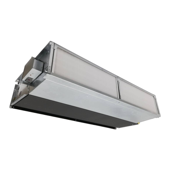
Venkon XL UL Assembly, installation and operating instructions Construction and function Overview Fig. 1: Venkon XL at a glance (example ceiling version) Float switch Water connection Actuator Valve condensate tray Condensate pump Filter Main condensate drip tray Control (hidden) Heat exchanger... -
Page 16: Brief Description
Venkon XL UL Assembly, installation and operating instructions Brief description Venkon XL are decentralised units for the heating, cooling and filtering of air, for use in hotels, offices and business premises, among others. Secondary air is drawn in filtered by the fan and passed through the copper/aluminium heat exchanger. Here the air is either heated or cooling depending on the temperature of the water in the heat exchanger. -
Page 17: Installation And Wiring
Venkon XL UL Assembly, installation and operating instructions Installation and wiring Definition of the connection side Example ceiling mounting, left connection left Example ceiling mounting, right connection Fig. 2: Ceiling mounting, left and right connection Example wall mounting, left connection Example wall mounting, right connection... -
Page 18: Requirements Governing The Installation Site
Venkon XL UL Assembly, installation and operating instructions Requirements governing the installation site Only install and assemble the unit if the following conditions are met: Make sure that the wall/ceiling is sufficiently load-bearing to take the weight of the unit (Technical data [} 12]). -
Page 19: Installation
Venkon XL UL Assembly, installation and operating instructions Installation 2 people are needed to install the unit. CAUTION! Risk of injury from sharp metal housing! The inner metal of the casing can have sharp edges. Wear suitable protective gloves. IMPORTANT NOTE! Horizontal installation of units! When installing the units, ensure that they are completely horizontal to ensure proper operation. -
Page 20: Installation Of Casing
Venkon XL UL Assembly, installation and operating instructions 6.4.1 Installation of basic unit Note the Venkon minimum clearances when installing the basic units! Highlight the dimensions and clearances of the key holes on the wall or ceiling as per the table, drill the holes and use appropriate fixing materials to install the basic unit. - Page 21 Venkon XL UL Assembly, installation and operating instructions 39.4 Size 1 51.2 Size 2 68.9 Size 3 82.7 Size 4 Fig. 5: Views cladding (simplified representation) The cladding depth X for all sizes is 275 mm / 10.8 inches. By means of the holes in the side panels (see detail X), the cladding can be fixed to the wall for better fixation.
- Page 22 Venkon XL UL Assembly, installation and operating instructions Fit the fixing brackets for the casing. Glue the spacers; maintain a min. distance of 2 cm from above to prevent the edge of the casing from colliding with the spacers. Position the casing on the basic unit.
- Page 23 Venkon XL UL Assembly, installation and operating instructions Attach the casing to the basic unit. Attach the suction panel to the basic unit.
-
Page 24: Installation Of Sheet Steel Accessories
Venkon XL UL Assembly, installation and operating instructions 6.4.3 Installation of sheet steel accessories Overview, air side steel sheet accessories Fig. 6: Schematic layout of steel sheet accessories for ceiling mounting Air duct bend 90° Splitter silencer Elastic connecting piece Flex pipe connection unit Ø 198 mm (other diameters available... - Page 25 Venkon XL UL Assembly, installation and operating instructions Figure Description Dimensions [inch] 22.54 34.3 65.7 Air duct bend 90° 20.9 32.7 50.4 64.2 22.54 34.3 65.7 Elastic connecting piece 20.9 32.7 50.4 64.2 3 5 . Inspection hatch with frame 4 / 4 3 7 .
- Page 26 Venkon XL UL Assembly, installation and operating instructions Frame connection dimensions Size 1 Size 2 Size 3 Size 4 Fig. 7: Frame connection dimensions...
-
Page 27: Installation
When using the units without filters, ensure that the unit is operated at a maximum of 7.3 V, otherwise condensate may drip. This will not happen with Kampmann filters installed. When using filters not approved by the manufacturer, no guarantee regarding the performance specifications can be... -
Page 28: Connection To The Pipe Network
Venkon XL UL Assembly, installation and operating instructions 6.5.1 Connection to the pipe network The supply and return connections are located on the left or right side of the unit, as seen in the direction of the air flow. The piping must be laid in such a way that no mechanical stresses are transferred to the heat exchanger and the accessibility of the unit during maintenance and repair work is not impaired. - Page 29 Venkon XL UL Assembly, installation and operating instructions Wall unit Wall unit Ceiling unit, right connection Right connection Left connection in in in in in in in in in in in in Ceiling unit, left connection in in in in...
- Page 30 Venkon XL UL Assembly, installation and operating instructions Dimensions [mm], left connection side Dimensions [mm], right connection side ø15 ø15 ø15 ø15 Left side view, Left side view, Right side view, Right side view, 2-pipe 4-pipe 4-pipe 2-pipe Dimensions [inch], left connection side Dimensions [inch], right connection side ø0.6...
-
Page 31: Overview Of Valve Kits
Venkon XL UL Assembly, installation and operating instructions 6.5.2 Overview of valve kits Accessories recirculation basic unit, water side, factory mounted on base unit Mounting water con- 2-pipe version with nection left preset 2-way valve, Item no. Suitable for all sizes... -
Page 32: Connection Of 2-Way Valve Kit
Venkon XL UL Assembly, installation and operating instructions 6.5.3 Connection of 2-way valve kit 2-way valve kit, wall mounting, 2-pipe, left 2-way valve kit, wall mounting, 4-pipe, left connection connection side side Front view Side view Front view Side view... - Page 33 Venkon XL UL Assembly, installation and operating instructions 2-way valve kit, ceiling mounting, 2-pipe, left 2-way valve kit, ceiling mounting, 4-pipe, left connection side connection side Back wall Back wall Front view Side view Side view Front view Bottom view...
-
Page 34: Connection Of Differential Pressure-Dependent Valve Kit
Venkon XL UL Assembly, installation and operating instructions 6.5.4 Connection of differential pressure-dependent valve kit Valve kit differential pressure independent, wall Valve kit differential pressure independent, wall mounting, 2-pipe, left side connection mounting, 4-pipe, left side connection Front view Side view... - Page 35 Venkon XL UL Assembly, installation and operating instructions Valve kit differential pressure independent, ceiling Valve kit differential pressure independent, ceiling mounting, 2-pipe, left side connection mounting, 4-pipe, left side connection Back wall Back wall Side view Front view Side view...
-
Page 36: Connection, On-Site Pipework
Venkon XL UL Assembly, installation and operating instructions 6.5.5 Connection, on-site pipework Fig. 14: Bottom view (base unit with cladding) -
Page 37: Condensation Connection
Venkon XL UL Assembly, installation and operating instructions 6.5.6 Condensation connection 6.5.6.1 Condensation drain with natural gradient A condensate drain provided by the customer must be connected to a condensate drain socket of the Venkon (size of drain 15 mm / 0.6 inch) and fastened accordingly. To ensure condensation drainage from the base unit, the slope must be at least 1 % without restriction and without rising pipe sections (according to DIN EN 12056;... - Page 38 Venkon XL UL Assembly, installation and operating instructions Connecting the condensate pump Push the suction hose as far as it will go and fix in place with a cable tie to prevent the pump from running dry. Cable tie Suction connection...
- Page 39 Pumpenkörper Werkseitig installierte Sicherung Kabelbinder Austauschbarer Filter Digitaler Sensor Abmessungen der Pumpe Wasserbehälter Venkon XL UL Dip-Schalter USB-Anschluss Diagnose-LED Assembly, installation and operating instructions Wandrückenplatte 53mm 286mm Abdeckung Product description Combi Kit beinhaltet Diagnostic LED USB port Mitgeliefertes Zubehör Diagnose-LED...
- Page 40 Venkon XL UL Assembly, installation and operating instructions DO NOT use tools to connect the tubing. DO NOT use tools to connect the tubing. Ensure the evaporator coils are free of chemicals before reinstalla- Ensure the evaporator coils are free of chemicals before reinstalla- tion of the REFCO Combi pump.
-
Page 41: Electrical Connection
Venkon XL UL Assembly, installation and operating instructions Electrical connection IMPORTANT NOTE! Condensation formation in the cooling unit! In the event of on-site valve control, the cooling valve must be closed when the fans are switched off. Maximum electrical rating values... -
Page 42: Electromechanical Control
Venkon XL UL Assembly, installation and operating instructions Electromechanical control 7.2.1 Connection (U02M) The junction box for electromechanical control (EC) as well as the junction box for the condensation monitor can be electric- ally installed separately from the side panel of the basic unit. -
Page 43: Pre-Commissioning Checks
Venkon XL UL Assembly, installation and operating instructions Pre-commissioning checks When commissioning the device for the first time, ensure that all the necessary requirements are met so that the device can function safely and in accordance with its intended use. -
Page 44: Maintenance
Venkon XL UL Assembly, installation and operating instructions Maintenance Securing against reconnection DANGER! Risk of death by unauthorised or uncontrolled restart! Unauthorised or uncontrolled restarting of the equipment can result in serious injury or death. Before restarting, ensure that all safety devices are fitted and working properly and that there is no haz- ard to humans. -
Page 45: Maintenance Schedule
Venkon XL UL Assembly, installation and operating instructions Maintenance Schedule: The sections below describe maintenance work needed for the proper and trouble-free operation of the equipment. If there are signs of increased wear during regular checks, shorten the required maintenance intervals to the actual wear and teat. -
Page 46: Maintenance Work
Venkon XL UL Assembly, installation and operating instructions Maintenance work 9.3.1 Replacing the filter. CAUTION! Risk of injury from sharp metal housing! The inner metal of the casing can have sharp edges. Wear suitable protective gloves. Loosen the screws of the filter cover. -
Page 47: Visual Checks
Venkon XL UL Assembly, installation and operating instructions 9.3.2 Visual checks Clean the heat exchanger. Check the heat exchanger for soiling and carefully vacuum if necessary. Avoid damage to the pipework and fins. 9.3.3 Cleaning the main condensation tray Loosen the main condensate tray screws. -
Page 48: Cleaning The Float Switch
Venkon XL UL Assembly, installation and operating instructions Clean the main condensate tray. 9.3.4 Cleaning the float switch Pull off the float switch from the Velcro. Clean the float switch. Pull the yellow strainer out of the intake area, clean it as well and reinsert it. -
Page 49: Faults
Venkon XL UL Assembly, installation and operating instructions Faults The following chapter describes possible causes of faults and the work needed to rectify them. Should faults occur frequently, shorten the maintenance intervals in line with the actual loading on the unit. -
Page 50: Fault Table
Venkon XL UL Assembly, installation and operating instructions 10.1 Fault table Fault Possible cause Remedy Check voltage, switch on repair switch. No function. No power supply. Replace fuse. Heat exchanger defect. Replace heat exchanger if necessary. System water leakage Hydraulic connection not correct. -
Page 51: Certificates
This document is the property of Intertek Testing Services and is not transferable. The certification mark(s) may be applied only at the location of the Party Authorized To Apply Mark. Applicant: Kampmann GmbH & Co. KG Manufacturer: Kampmann GmbH & Co. KG Friedrich-Ebert-Str. - Page 52 Venkon XL UL Assembly, installation and operating instructions AUTHORIZATION TO MARK Models: 3480 followed by 1, 2, 3 or 4; followed by 10; followed by 3 or 4; followed by 03; followed by 2 or 4; followed by UL. 34821 followed by W or D; followed by 0; followed by L or R; followed by 2 or 4; followed by 1, 2, 3, or 4;...
- Page 53 Report. This document is the property of Intertek Testing Services and is not transferable. The certification mark(s) may be applied only at the location of the Party Authorized To Apply Mark. Kampmann GmbH & Co. KG Kampmann Poslka Sp.z.o.o Applicant: Manufacturer: Lotnicza 21, 99-100 Łęczyca...
- Page 54 Venkon XL UL Assembly, installation and operating instructions AUTHORIZATION TO MARK Models: 3480 followed by 1, 2, 3 or 4; followed by 10; followed by 3 or 4; followed by 03; followed by 2 or 4; followed by UL. 34821 followed by W or D; followed by 0; followed by L or R; followed by 2 or 4; followed by 1, 2, 3, or 4;...
- Page 55 Venkon XL UL Assembly, installation and operating instructions Table Tab. 1 Operating limits ..............................7 Tab. 2 Operating voltage ..............................7 Tab. 3 Water quality................................7 Tab. 4 Technical specifications 115 V..........................13 Tab. 5 Technical specifications 208 V..........................13 Tab.
- Page 56 Country Contact Kampmann Heating, Cooling, Ventilation Ltd. 1625 Dilworth Drive Unit #207 Kelowna, BC Canada V1Y 8M4 Canada T +1 604/ 3621080 F +1 604/ 6871327 E info@kampmann.ca W Kampmann.ca...
Need help?
Do you have a question about the Venkon XL UL and is the answer not in the manual?
Questions and answers