
Subscribe to Our Youtube Channel
Related Manuals for Kampmann KaCool W


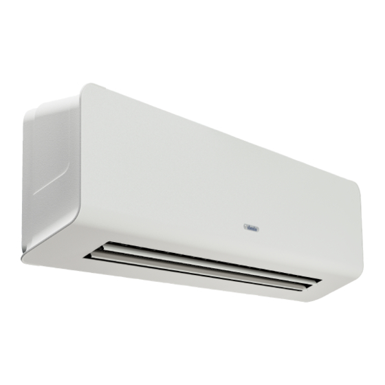
Summary of Contents for Kampmann KaCool W
- Page 1 KaCool W ► Assembly, installation and operating instructions Keep these instructions in a safe place for future use! Issue08/23EN SAP No.1537631...
-
Page 3: Table Of Contents
Table of contents 1 General ..........................5 1.1 About these instructions ........................1.2 Explanation of Symbols.......................... 2 Safety............................ 6 2.1 Correct use............................. 2.2 Limits of operation and use........................2.3 Risk from electrocution!......................... 2.4 Personnel requirements - Qualifications ....................2.5 Personal Protective Equipment ......................3 Transport, storage and packaging.................. - Page 4 7.4.1 KaController installation..........................41 7.4.2 Connection (*C1)............................42 8 Pre-commissioning checks....................46 9 Operation..........................47 9.1 Operation of electromechanical control ....................47 9.2 Operation of the KaController........................ 50 9.2.1 Function keys, display elements ........................ 50 10 Maintenance ......................... 53 10.1 Securing against reconnection ....................... 53 10.2 Maintenance Schedule:..........................
-
Page 5: General
KaCool W Assembly, installation and operating instructions General About these instructions These instructions ensure the safe and efficient handling of this equipment. These instructions form an integral part of the equipment and have to be kept in the direct vicinity of the equipment and available to personnel at all times. -
Page 6: Safety
KaCool W Assembly, installation and operating instructions Safety This section provides an overview of all important safety aspects to ensure optimum protection of personnel as well as safe and trouble-free operation. In addition to the safety instructions in these operating instructions, the valid safety, accident pre- vention and environmental protection regulations must be observed for the area of use of the unit. - Page 7 KaCool W Assembly, installation and operating instructions Limits of operation and use Limits of operation Min./max. water temperature °C 6-75 Min./max. air intake temperature °C 15-30 Min./max. air humidity max. 63% Min. operating pressure bar/kPa Max. operating pressure bar/kPa 8/800 Min./max.
-
Page 8: Risk From Electrocution
KaCool W Assembly, installation and operating instructions IMPORTANT NOTE! Danger of frost in cooling mode! There is a risk of the heat exchanger freezing when used in unheated rooms. Make sure that the unit is equipped with a frost protection sensor and/or thermostat in this case. -
Page 9: Personnel Requirements - Qualifications
KaCool W Assembly, installation and operating instructions Personnel requirements - Qualifications Expertise The installation of this product requires specialist knowledge of heating, cooling, ventilation, installation and electrical engin- eering. This knowledge, generally learned in professional training in one of the fields mentioned above, is not described sep- arately. -
Page 10: Transport, Storage And Packaging
IMPORTANT NOTE! Warranty claims can only be made within the applicable period for complaints. (More information is avail- able in the T&Cs on the Kampmann website) IMPORTANT NOTE! 2 people are needed to transport the unit. Wear personal protective clothing when transporting the unit. -
Page 11: Storage
KaCool W Assembly, installation and operating instructions Storage Store packaging under the following conditions: Do not store outdoors. Store in a dry and dust-free place. Store in a frost-free place. Do not expose to aggressive media. Protect from direct sunlight. -
Page 12: Technical Data
KaCool W Assembly, installation and operating instructions Technical data Unit KaCool W Size Width [mm] Length [mm] 1235 Height [mm] Weight [kg] Air volume flow [m³/h] 238-608 292-822 Internal volume of 2-pipe system [l] Heat output [W] 3418-6887 4424-10166 Cooling output [W]... -
Page 13: Construction And Function
Brief description The KaCool W is a decentralised design wall-mounted unit for heating and cooling air in hotels, offices and business premises, among other places. The secondary air is drawn in through a regenerable air filter, which removes dust from the secondary air, protecting the downstream components from dirt. -
Page 14: Installation And Wiring
KaCool W Assembly, installation and operating instructions Installation and wiring Requirements governing the installation site Only install and assemble the unit if the following conditions are met: Make sure that the wall is sufficiently load-bearing to take the weight of the unit (Technical data [} 12]). -
Page 15: Suspending The Unit
KaCool W Assembly, installation and operating instructions Installation 2 people are needed to install the unit. CAUTION! Risk of injury from sharp metal housing! The inner metal of the casing can have sharp edges. Wear suitable protective gloves. IMPORTANT NOTE! Horizontal installation of units! When installing the units, ensure that they are completely horizontal to ensure proper operation. - Page 16 KaCool W Assembly, installation and operating instructions 6.3.1 Suspending the unit Use the template (which is part of the packaging) to mark on the suspension points: ≥ 200 mm ≥ 1500 mm Fig. 3: Drilling template Dimensions of the suspension points, size 1/ size 2 Fig. 4: Size 1/ size 2 suspension points...
- Page 17 KaCool W Assembly, installation and operating instructions Remove the fixing screws and remove the design panel. Fix the basic unit to the wall using screws and rawlplugs (provided by others). Once the basic unit has been installed, make the water- side and electrical connections.
-
Page 18: Installation
KaCool W Assembly, installation and operating instructions Installation 6.4.1 Connection to the pipe network Fig. 6: Connecting dimensions Supply ½” Return ½” Condensate connection (Ø16 mm) -
Page 19: Overview Of Valve Kits
KaCool W Assembly, installation and operating instructions 6.4.2 Overview of valve kits Valve kits Article Properties Dimensions For use with Article no. [mm] 2-pipe, 2-way valve, 1x 230 V 2-point actuator 230 V Open/ Close, 50 Hz, 1/2” connection, 324002012110 KVS value 1.7 m³/h, max. - Page 20 KaCool W Assembly, installation and operating instructions Valve kit dimensions 2-way valve 3-way valve Differential pressure-independent valve Fig. 7: KaCool W valve kits...
-
Page 21: Condensate Drainage Using A Condensate Pump
KaCool W Assembly, installation and operating instructions 6.4.3 Condensate drainage using a condensate pump The water is drawn off by the condensate pump and discharged along a hose (supplied loose) connected on the pressure side. Depending on conditions on site, the water can be discharged into drainage lines, possibly with a trap connection. -
Page 22: Electrical Connection
7.2.1 Connection (*00) Circuit description, KaCool W electromechanical 230 V (*00) All KaCool W require a 230 V AC power supply. Factory-fitted actuators are wired to the terminals. The appropriate terminals are available for valve actuators. The fan speed of the EC fans used can be continuously variably controlled by a 0–10 V DC signal. The internal motor electronics detects any possible motor malfunction and automatically switches off the fan. - Page 23 KaCool W Assembly, installation and operating instructions Terminals Site connection Internal connection Optional / supplied loose Motor L Condensate pump L Mains power supply line Motor N 0 - 10 V 0 - 10 V Optional jumper (N) Jumper N (by others)
- Page 24 KaCool W Assembly, installation and operating instructions Elektromechanisch 230 V, 2-Leiter Ventilantrieb 230V AC Auf/Zu, Kondensatpumpe optional, Ansteuerung 0-10 V DC über GA...
- Page 25 KaCool W Assembly, installation and operating instructions Elektromechanisch 230V, 2-Leiter, Ventilantrieb 230VAC Auf/Zu, Kondensatpumpe optional, mit Klimaregler Typ 14894x...
- Page 26 KaCool W Assembly, installation and operating instructions Elektromechanisch 230V, 2-Leiter Ventilantrieb 230V AC Auf/Zu, Kondensatpumpe optional, mit Raumthermostat Typ 30155...
- Page 27 KaCool W Assembly, installation and operating instructions Elektromechanisch, 2-Leiter, Ventilantrieb 230VAC Auf/Zu, Kondensatpumpe optional, mit Uhrenthermostat Typ 30256...
- Page 28 KaCool W Assembly, installation and operating instructions...
- Page 29 KaCool W Assembly, installation and operating instructions...
- Page 30 KaCool W Assembly, installation and operating instructions...
- Page 31 KaCool W Assembly, installation and operating instructions...
-
Page 32: Infra-Red Remote Control Version
KaCool W Assembly, installation and operating instructions Infra-red remote control version Fig. 9: Attaching the infra-red receiver Note: When inserting and removing the receiver, always tilt the plug as shown on the figure to avoid breaking the plug. - Page 33 KaCool W Assembly, installation and operating instructions Symbols 1 Display of reception ° 2 Fan speed ° 3 Temperature display 4 Temperature unit of measure 5 Current time 6 Timer ON 7 Timer OFF 8 Time (AM – before midday / PM – after midday)
- Page 34 KaCool W Assembly, installation and operating instructions 1. Switching on / off Press POWER to switch the unit on or off. Once the unit has been switched on, it is operated in accordance with the setting displayed on the remote control.
- Page 35 KaCool W Assembly, installation and operating instructions 5. Timer ON The unit can be programmed to switch on in advance. Press ON and the symbol (ON TIME) appears. Press to change the time (+ 1 minute). Press and hold down for 3 seconds to increase the time in 10-minute increments.
- Page 36 KaCool W Assembly, installation and operating instructions Dry function Dry mode is a predefined cooling working cycle control. Only temperature control is permitted in this mode. The fan works automatically and only at minimum speed. There are four pre-defined operating zones A-B-C-D and three neutral zones in which the function remains unchanged (the previous function is repeated).
- Page 37 KaCool W Assembly, installation and operating instructions Replacing the remote control batteries If the remote control batteries start to lose power, the display becomes dimmer until it completely goes out if the batteries are not replaced. Replace the batteries as follows: Push down the battery cover and remove.
- Page 38 KaCool W Assembly, installation and operating instructions Functional description of the infra-red PCB DIP no. Function Standard System type 4-pipe 2-pipe VH out Not used Valve Regulation type Wall terminal Infra-red receiver Motor type 3 speeds 0-10 V DC (EC)
- Page 39 KaCool W Assembly, installation and operating instructions DIP switch “Address” functional logic Address DIP switch to be set Address DIP switch to be set Address DIP switch to be set Not assigned 1,3,5 2,4,6 2,3,5 1,2,4.6 1,2,3.5 3,4,6 1,3,4.6 1,4,5 2,3,4.6...
- Page 40 KaCool W Assembly, installation and operating instructions LED display (normal operation) LED display Meaning Unit status LED is switched off. Unit is switched off or in fan mode. Unit is switched off or in fan mode. LED steady blue light...
-
Page 41: Kacontrol (*C1)
KaCool W Assembly, installation and operating instructions KaControl (*C1) 7.4.1 KaController installation Fig. 11: Installation of flush-mounted back box Electrical connection Connect the KaController to the nearest KaControl unit in line with the wiring diagram. The maximum bus length between the KaController and the KaControl master unit is 30 m. -
Page 42: Connection (*C1)
KaCool W Assembly, installation and operating instructions 7.4.2 Connection (*C1) General information Route all low voltage cables along the shortest route. Ensure that low-voltage and power cables are separated, using metal partitions on cable harnesses. Wrong! Use only shielded cables as low-voltage and bus cables. - Page 43 Assembly, installation and operating instructions Circuit description KaCool W (*C1) All KaCool W need a 230 V / 50 Hz power supply. Factory-fitted actuators are wired to the terminals. The speed of the EC fans used is controlled by a 0-10 V DC signal from the KaControl.
- Page 44 KaCool W Assembly, installation and operating instructions KaControl C1, 2-Leiter, Ventilantrieb 24VDC Auf/Zu, Ansteuerung 0-10V DC über GA...
- Page 45 KaCool W Assembly, installation and operating instructions KaControl C1, 2-Leiter, Ventilantrieb 24VDC Auf/Zu, mit KaController Typ 321000x...
-
Page 46: Pre-Commissioning Checks
KaCool W Assembly, installation and operating instructions Pre-commissioning checks When commissioning the device for the first time, ensure that all the necessary requirements are met so that the device can function safely and in accordance with its intended use. Structural tests Check that the unit is securely standing and fixed. -
Page 47: Operation
KaCool W Assembly, installation and operating instructions Operation Operation of electromechanical control Room thermostat, type 196000148915/ 196000148918/ 196000148917 Electronic room thermostat with 3-stage switch for 2-pipe applications, surface- mounted wall mounting on a flush-mounted box in visually unobtrusive design. Parallel operation of 2 units is possible. - Page 48 KaCool W Assembly, installation and operating instructions Room thermostat, type 30155 Electronic room thermostat with 3-stage automatic function for 2- and 4- pipe applications, surface-mounted wall installation on a flush-mounted box in visually unobtrusive design simple operation using a large rotary dial for temperature setting with...
- Page 49 KaCool W Assembly, installation and operating instructions Climate controller, white, type 196000148941 for 2- and 4-pipe applications, surface-mounted wall installation on a flush- mounted box with a visually unobtrusive design with 2.5” LCD display and high-quality glass finish with capacitive keys...
-
Page 50: Operation Of The Kacontroller
KaCool W Assembly, installation and operating instructions Climate controller, white, type 196000148943 with Modbus interface for 2- and 4-pipe applications, surface-mounted wall installation on a flush- mounted box with a visually unobtrusive design with 2.5” LCD display and high-quality glass finish with capacitive keys... - Page 51 KaCool W Assembly, installation and operating instructions 9.2.1 Function keys, display elements All menus can be selected and set using the navigator dial. The LED background lighting is automatically switched off 5 seconds after the KaController is last used. The LED background lighting can be permanently disabled using a parameter setting.
- Page 52 KaCool W Assembly, installation and operating instructions The symbols shown on the display depend on the application (2-pipe, 4-pipe etc.) and the parameters set. Fig. 27: Display Display of setpoint room temperature Current time Timer program enabled Weekday Alarm Selected function is locked “External ventilation“...
-
Page 53: Maintenance
KaCool W Assembly, installation and operating instructions Maintenance 10.1 Securing against reconnection DANGER! Risk of death by unauthorised or uncontrolled restart! Unauthorised or uncontrolled restarting of the equipment can result in serious injury or death. Before restarting, ensure that all safety devices are fitted and working properly and that there is no haz- ard to humans. -
Page 54: Maintenance Work
KaCool W Assembly, installation and operating instructions 10.3 Maintenance work Open the design panel before maintenance work! Open the design panel before maintenance work, as described in "Installing the unit on the ceiling". 10.3.1 Replacing the filter. CAUTION! Risk of injury from sharp metal housing! The inner metal of the casing can have sharp edges. -
Page 55: Faults
KaCool W Assembly, installation and operating instructions Faults The following chapter describes possible causes of faults and the work needed to rectify them. Should faults occur frequently, shorten the maintenance intervals in line with the actual loading on the unit. -
Page 56: Kacontrol Faults
KaCool W Assembly, installation and operating instructions 11.2 KaControl faults Code Alarms Priority Faulty control sensor. Motor fault. Room frost protection. Condensation alarm. General alarm. Sensor AI1, AI2 or AI3 faulty. Unit frost protection. EEPROM error. Offline slave in the CAN bus network. -
Page 57: List Of Kacontrol Parameters
Ventilation temperature activation °C P031 Ventilation interval °C P032 Flushing function: maximum idle time of fan min. P033 Flushing function: duration of the flushing function P034 Flushing function: activation in operating modes Parameter key KaCool W , SAP no.9001386, dated 10.07.2020... - Page 58 KaCool W Assembly, installation and operating instructions Parameter Function Standard Min. Max. Unit KaCool W Fan run-on time after an operating mode is switched to P035 stage 1 P036 Type of setpoint setting P037 Display P038 Lock/disable function on the control unit...
- Page 59 KaCool W Assembly, installation and operating instructions Parameter Function Standard Min. Max. Unit KaCool W P076 Serial address of slave 6 P077 Serial address of slave 7 P078 Serial address of slave 8 P079 Serial address of slave 9 P080...
- Page 60 KaCool W Assembly, installation and operating instructions Parameter Function Standard Min. Max. Unit KaCool W P119 Off delay time P120 reserved P121 reserved P122 Relative fan speed increase via contact P123 Maximum valve running time Minimum P + I output variation for valve movement (0 to...
-
Page 61: Kacontroller Parameter List
KaCool W Assembly, installation and operating instructions 12.2 KaController parameter list Para- Function Standard Min. Max. Unit Comment meter Address in Mod- t001 Serial address bus network Baud rate 0 = Baud rate 4800 t002 1 = Baud rate 9600... -
Page 62: Certificates
KaCool W Assembly, installation and operating instructions Certificates EU-Konformitätserklärung EU Declaration of Conformity Déclaration de Conformité CE Deklaracja zgodności CE EU prohlášení o konformite KAMPMANN Wir (Name des Anbieters, Anschrift): GMBH & Co. KG We (Supplier’s Name, Address): Friedrich-Ebert-Str. 128-130... - Page 63 KaCool W Assembly, installation and operating instructions Gemäß den Bestimmungen der Richtlinien: Following the provisions of Directive: Conformément aux dispositions de Directive: Zgodnie z postanowieniami Dyrektywy: Odpovídající ustanovení směrnic: 2014/30/EU EMV-Richtlinie 2014/35/EU Niederspannungsrichtlinie 2011/65/EU RoHS Lingen (Ems), den 26.06.2023 Frank Bolkenius__________________...
-
Page 64: Table
KaCool W Assembly, installation and operating instructions Table Tab. 1 Limits of operation ..............................7 Tab. 2 Operating voltage ..............................7 Tab. 3 Water quality................................7 Tab. 4 Valve kit at a glance............................... 19 Tab. 5 Maximum electrical rating values .......................... 22 Tab. - Page 68 Land Kontakt Country Contact Kampmann GmbH & Co. KG Kampmann UK Ltd. Friedrich-Ebert-Str. 128 - 130 Dial House, Govett Avenue 49811 Lingen (Ems) Shepperton, Middlesex, TW17 8AG T +49 591/ 7108-660 T +44 1932/ 228592 Germany Great Britain...
Need help?
Do you have a question about the KaCool W and is the answer not in the manual?
Questions and answers