Advertisement
Table of Contents
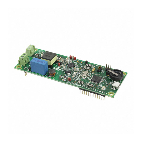
STEVAL-IPP003V1
100nF/25V - 0402
Schematic diagram
Figure 1. Power supply
VCC
C1
R1
100K - 0603
C4
100nF/25V - 040
JP1
OPEN
Figure 2. ST7580 reset button (micro-switch)
1
Figure 3. ST7580 UART interface
T_REQ
TP11
GND
Screw Connector 3P 2.5mm
U1
5
4
IN
OUT
1
SHDN
C2
3
BYPASS
10u/6.3V - 0603
2
G
ND
2
LK112SM33TR
SW 1
2
C17
100nF/25V - 0402
TP9
T_REQ
TXD
RXD
1
CN1
VDDIO
VCC
C3
100nF/25V - 0402
GSPG06112013DI1025
RESETN
GSPG06112013DI1030
TP8
TXD
TP12
RXD
GSPG06112013DI1035
J7
1
2
3
CON3
Advertisement
Table of Contents

Summary of Contents for ST STEVAL-IPP003V1
- Page 1 STEVAL-IPP003V1 Schematic diagram Figure 1. Power supply Screw Connector 3P 2.5mm CON3 VDDIO SHDN 100nF/25V - 0402 100nF/25V - 0402 100K - 0603 BYPASS 10u/6.3V - 0603 100nF/25V - 040 LK112SM33TR OPEN GSPG06112013DI1025 Figure 2. ST7580 reset button (micro-switch) SW 1...
- Page 2 Figure 4. DC BUS / AC BUS OUTPUT(+) BUS(+) OUTPUT(-) BUS(-) GSPG06112013DI1040 Figure 5. Current limit setting VDDIO 330 - 0402 10k - 0603 4NF06L CL_SEL 130 - 0402 100pF/C0G - 0402 GSPG06112013DI1045 Figure 6. Microcontroller connection VDDIO GPIO_P1 GPIO_BR0 CLOSE GPIO_P2 GPIO_BR1...
- Page 3 Figure 7. ST7580 module - PLM GSPG06112013DI1055 RX_ON T_REQ TX_ON GND_SIGNAL...
- Page 4 Figure 8. ST7580 module - MCU GSPG06112013DI1100...


Need help?
Do you have a question about the STEVAL-IPP003V1 and is the answer not in the manual?
Questions and answers