
Related Manuals for Pilz PSSu E S RS232


Summary of Contents for Pilz PSSu E S RS232
- Page 1 PSSu E S RS232(-T) Decentralised system PSSuniversal I/O Operating Manual 1001378-EN-04...
- Page 2 Preface This document is a translation of the original document. All rights to this documentation are reserved by Pilz GmbH & Co. KG. Copies may be made for internal purposes. Suggestions and comments for improving this documentation will be gratefully received.
-
Page 3: Table Of Contents
Changing an electronic module during operation Section 6 Wiring General wiring guidelines 6.1.1 Mechanical connection of the base modules Terminal configuration Connecting the module Section 7 Operation Messages Display elements 7.2.1 Display element for operational readiness Operating Manual PSSu E S RS232(-T) 1001378-EN-04... - Page 4 Contents 7.2.2 Display element for module error 7.2.3 Display elements for data transmission Section 8 Technical details Section 9 Order reference Product Accessories Operating Manual PSSu E S RS232(-T) 1001378-EN-04...
-
Page 5: Operating Manual Pssu E S Rs232(-T)
Introduction Validity of documentation This documentation is valid for the products PSSu E S RS232 and PSSu E S RS232-T. It is valid until new documentation is published. This operating manual explains the function and operation, describes the installation and provides guidelines on how to connect the product. -
Page 6: Definition Of Symbols
It also highlights areas within the text that are of particular import- ance. INFORMATION This gives advice on applications and provides information on special fea- tures. Operating Manual PSSu E S RS232(-T) 1001378-EN-04... -
Page 7: Overview
Max. number per system: 6 LEDs for: – Operational readiness – Module error – Data transmission For standard applications in system environment A and B T-type: PSSu E S RS232-T: for increased environmental requirements Operating Manual PSSu E S RS232(-T) 1001378-EN-04... -
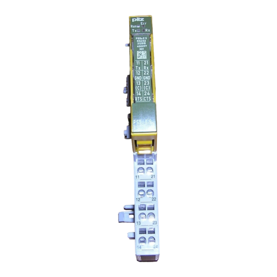
Page 8: Front View
2D code 3: Labelling strip for the terminal configuration on the base module 4: Name of electronic module 5: Connection level 1 6: Connection level 2 7: Connection level 3 8: Connection level 4 Operating Manual PSSu E S RS232(-T) 1001378-EN-04... - Page 9 10: Round connection holes (connection levels 1, 2, 3 and 4) for connecting the signal lines 11: Mounting slot for colour marker to label the connection level (connection levels 1, 2, 3 and 4) Operating Manual PSSu E S RS232(-T) 1001378-EN-04...
-
Page 10: Safety
PAS4000 from Version 1.1.1 – We recommend that you always use the latest version (download from www.pilz.de). The PSSu E S RS232 module may be used in conjunction with the following base modules: PSSu BP 1/8 S PSSu BP 1/8 C... -
Page 11: Safety Regulations
In safety-related applications, please comply with the mission time T in the safety-re- lated characteristic data. When decommissioning, please comply with local regulations regarding the disposal of electronic devices (e.g. Electrical and Electronic Equipment Act). Operating Manual PSSu E S RS232(-T) 1001378-EN-04... -
Page 12: Function Description
All the configuration data is stored in the head module and is assigned to the module on restart. This way the configuration data is retained even if you change the module. Operating Manual PSSu E S RS232(-T) 1001378-EN-04... -
Page 13: Integrated Protection Mechanisms
Bus termination error Data exchange Data is exchanged between subscribers via a special protocol based on the Modbus ASCII protocol. INFORMATION The necessary function block is available from Technical Support (tele- phone: +49 711 3409-444). Operating Manual PSSu E S RS232(-T) 1001378-EN-04... -
Page 14: Configuration
4.4.2 Receive buffer threshold The number of Bytes in a receive buffer of the module is defined with this value, from which the status bit "Receive buffer full" is set (default value: 512). Operating Manual PSSu E S RS232(-T) 1001378-EN-04... -
Page 15: Installation
5.1.1 Dimensions Base modules with four connection levels: 12,6 mm 8,1 mm 52,1 mm (0.496") (0.319") (2.051") 12,6 mm 72,6 mm (0.496") (2.858") Operating Manual PSSu E S RS232(-T) 1001378-EN-04... - Page 16 Installation Base modules with six connection levels: 12,6 mm 8,1 mm 52,1 mm (0.496") (0.319") (2.051") 12,6 mm 72,6 mm (0.496") (2.858") Operating Manual PSSu E S RS232(-T) 1001378-EN-04...
-
Page 17: Installing The Base Module
Push the base module back [2] until you hear it lock into position. On the mounting rail, slide the base module to the left until you hear the two lateral mounting hooks on the adjacent module lock into position [3]. Schematic representation: Operating Manual PSSu E S RS232(-T) 1001378-EN-04... -
Page 18: Inserting And Removing An Electronic Module
The mechanics of the electronic modules are designed for 50 plug in/out cycles. 5.3.1 Inserting an electronic module Procedure: The electronic module must audibly lock into position [1]. Mark the electronic module using the labelling strips [2]. Schematic representation: Operating Manual PSSu E S RS232(-T) 1001378-EN-04... -
Page 19: Removing An Electronic Module
It is possible to change an electronic module during operation. However, changing an elec- tronic module during operation may cause an ST communication error. The configuration data is retained when a module is changed. Operating Manual PSSu E S RS232(-T) 1001378-EN-04... -
Page 20: Wiring
Insert the stripped cable into the round fixing hole [2], as far as it will go. – Tighten up the screw on the screw terminal. – Check that the cable is firmly seated. Operating Manual PSSu E S RS232(-T) 1001378-EN-04... - Page 21 Inputs/outputs on the counter modules: 1.5 mm (AWG16) – Analogue inputs/outputs: 1.5 mm (AWG16) – Communication cables: 1.5 mm (AWG16) – Test pulse outputs: 1.5 mm (AWG16) – Power supply: 2.5 mm (AWG12) – Functional earth: 2.5 mm (AWG12) Operating Manual PSSu E S RS232(-T) 1001378-EN-04...
-
Page 22: Terminal Configuration
Cage clamp terminals: PSSu BP 1/8 C PSSu BP 1/8 C-T 12-22: GND (12-22 linked within the base module) 13-23: Shield connection (13-23 linked within the base module) 14: Output RTS 24: Input CTS Operating Manual PSSu E S RS232(-T) 1001378-EN-04... - Page 23 13-23: Shield connection (13-23-16-26 linked within the base module) 14: Output RTS 24: Input CTS 15-25: GND (12-22-15-25 linked within the base module) 16-26: Shield connection (13-23-16-26 linked within the base module) Operating Manual PSSu E S RS232(-T) 1001378-EN-04...
- Page 24 (13-23 linked within the base module) 14: Output RTS 24: Input CTS 15-25: GND (12-22-15-25 linked within the base module) 16-26: C-rail supply, shield connection (13-23-16-26 linked within the base module) Operating Manual PSSu E S RS232(-T) 1001378-EN-04...
-
Page 25: Connecting The Module
Wiring Connecting the module Input and output circuit Without C-rail With C-rail With hardware handshake With hardware handshake Operating Manual PSSu E S RS232(-T) 1001378-EN-04... -
Page 26: Operation
Display element for operational readiness The module has an LED to display operational readiness ("Run" LED). Description Colour Status - - - Module not ready for oper- ation Green Module ready for operation Operating Manual PSSu E S RS232(-T) 1001378-EN-04... -
Page 27: Display Element For Module Error
The module has the LEDs Tx and Rx for displaying the data transfer (LEDs "Tx" and "Rx"). Meaning Designa- Colour Status Signal Terminal tion - - - No data transfer green Send data - - - No data transfer green Receive data Operating Manual PSSu E S RS232(-T) 1001378-EN-04... -
Page 28: Technical Details
Potential isolation between inter- face and periphery supply Environmental data 312515 314515 EN 60068-2-1, EN 60068-2-14, EN EN 60068-2-1, EN 60068-2-14, EN Climatic suitability 60068-2-2, EN 60068-2-30, EN 60068-2-2, EN 60068-2-30, EN 60068-2-78 60068-2-78 Operating Manual PSSu E S RS232(-T) 1001378-EN-04... - Page 29 In accordance with the standard EN 60529 EN 60529 Mounting area (e.g. control cab- inet) IP54 IP54 Housing IP20 IP20 IP20 IP20 Terminals Mechanical data 312515 314515 Material Bottom Front Coding Mounting type plug-in plug-in Operating Manual PSSu E S RS232(-T) 1001378-EN-04...
- Page 30 Width 12,6 mm 12,6 mm Depth 60,2 mm 60,2 mm 36 g 37 g Weight Mechanical coding Type Colour Dark grey Dark grey Where standards are undated, the 2009-03 latest editions shall apply. Operating Manual PSSu E S RS232(-T) 1001378-EN-04...
-
Page 31: Order Reference
Base module with C-rail and screw terminals, T-type 314 620 PSSu BP-C 1/12 C Base module with C-rail and cage clamp terminals 312 621 PSSu BP-C 1/12 C-T Base module with C-rail and cage clamp terminals, T-type 314 621 Operating Manual PSSu E S RS232(-T) 1001378-EN-04... - Page 32 Front cover Support Technical support is available from Pilz round the clock. Americas Australia Scandinavia Brazil +61 3 95446300 +45 74436332 +55 11 97569-2804 Spain Canada Europe +34 938497433 +1 888-315-PILZ (315-7459) Austria Switzerland +41 62 88979-30 Mexico +43 1 7986263-0...
Need help?
Do you have a question about the PSSu E S RS232 and is the answer not in the manual?
Questions and answers