
Subscribe to Our Youtube Channel
Related Manuals for Pilz PSSu E S 2DOR 2


Summary of Contents for Pilz PSSu E S 2DOR 2
- Page 1 PSSu E S 2DOR 2(-T) Decentralised system PSSuniversal I/O Operating Manual-22077-EN-06...
- Page 2 We do assure you that all persons are regarded without discrim- ination and on an equal basis. All rights to this documentation are reserved by Pilz GmbH & Co. KG. Copies may be made for the user's internal purposes. Suggestions and comments for improving this documenta- tion will be gratefully received.
-
Page 3: Table Of Contents
Mechanical connection of the base modules................Terminal configuration ......................Connecting the module......................Operation ..........................Messages ..........................Display elements ........................7.2.1 Display elements for module diagnostics ................. 7.2.2 Display elements for output status.................... Operating Manual PSSu E S 2DOR 2(-T) 22077-EN-06... - Page 4 Contents Technical details ........................Order reference ........................Product ............................. Accessories ..........................Operating Manual PSSu E S 2DOR 2(-T) 22077-EN-06...
-
Page 5: Introduction
Introduction Validity of documentation This documentation is valid for the products PSSu E S 2DOR 2 and PSSu E S 2DOR 2-T. It is valid until new documentation is published. This operating manual explains the function and operation, describes the installation and provides guidelines on how to connect the product. -
Page 6: Definition Of Symbols
It also highlights areas within the text that are of particular import- ance. INFORMATION This gives advice on applications and provides information on special fea- tures. Operating Manual PSSu E S 2DOR 2(-T) 22077-EN-06... -
Page 7: Overview
– Current load capacity per output: 2 A LEDs for: – Switch status of each output – Module error For standard applications in system environment A and B T-type: PSSu E S 2DOR 2-T: for increased environmental requirements Operating Manual PSSu E S 2DOR 2(-T) 22077-EN-06... -
Page 8: Front View
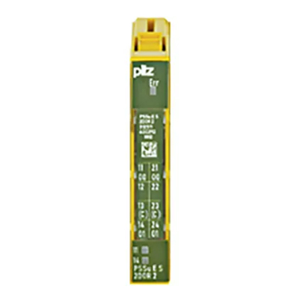
– 2D code 3: Labelling strip for the terminal configuration on the base module 4: Status LEDs 5: Name of electronic module 6: Connection level 1 7: Connection level 2 8: Connection level 3 Operating Manual PSSu E S 2DOR 2(-T) 22077-EN-06... - Page 9 11: Round connection holes (connection levels 1, 2, 3 and 4) for connecting the signal lines 12: Mounting slot for colour marker to label the connection level (connection levels 1, 2, 3 and 4) Operating Manual PSSu E S 2DOR 2(-T) 22077-EN-06...
-
Page 10: Safety
PAS4000 from version 1.7.0 – We recommend that you always use the latest version (download from www.pilz.de). The PSSu E S 2DOR 2 module may be used in conjunction with the following base mod- ules: PSSu BP 1/8 S PSSu BP 1/8 C... -
Page 11: Safety Regulations
Safety The module PSSu E S 2DOR 2-T may be used in conjunction with the following base mod- ules: PSSu BP 1/8 S-T PSSu BP 1/8 C-T PSSu BP-C 1/8 S-T PSSu BP-C 1/8 C-T PSSu BP 1/12 S-T PSSu BP 1/12 C-T... -
Page 12: Disposal
In safety-related applications, please comply with the mission time T in the safety-related characteristic data. When decommissioning, please comply with local regulations regarding the disposal of electronic devices (e.g. Electrical and Electronic Equipment Act). Operating Manual PSSu E S 2DOR 2(-T) | 12 22077-EN-06... -
Page 13: Function Description
Temperature monitoring The module provides the following diagnostic data: Start-up error Configuration error ST communication error Bus termination error Temperature error: too warm Temperature error: too hot Operating Manual PSSu E S 2DOR 2(-T) | 13 22077-EN-06... -
Page 14: Functions
Addresses in the process image The module occupies 2 consecutive bit addresses in the process image. Configuration SafetyBUS p Standard bus system FS-PIO ST-PII ST-PIO None - - - - - - 2 Bit Operating Manual PSSu E S 2DOR 2(-T) | 14 22077-EN-06... -
Page 15: Installation
5.1.1 Dimensions 25,2 mm 8,1 mm 52,1 mm (0.992") (0.319") (2.051") 25,2 mm 72,7 mm (0.992") (2.862") Operating Manual PSSu E S 2DOR 2(-T) | 15 22077-EN-06... -
Page 16: Installing The Base Module
Push the base module back [2] until you hear it lock into position. On the mounting rail, slide the base module to the left until you hear the two lateral mounting hooks on the adjacent module lock into position [3]. Schematic representation: Operating Manual PSSu E S 2DOR 2(-T) | 16 22077-EN-06... -
Page 17: Inserting And Removing An Electronic Module
This is how the base module is coded. The mechanics of the electronic modules are designed for 50 plug in/out cycles. Operating Manual PSSu E S 2DOR 2(-T) | 17 22077-EN-06... -
Page 18: Inserting An Electronic Module
Installation 5.3.1 Inserting an electronic module Procedure: The electronic module must audibly lock into position [1]. Mark the electronic module using the labelling strips [2]. Schematic representation: Operating Manual PSSu E S 2DOR 2(-T) | 18 22077-EN-06... -
Page 19: Removing An Electronic Module
– The substitute values are used for the modules' FS outputs, with Valid Bits = FALSE. CAUTION! Sparking can cause interference and errors! Only change the module when the load is switched off! Operating Manual PSSu E S 2DOR 2(-T) | 19 22077-EN-06... -
Page 20: Wiring
The terminal configuration as stated on the front plate applies for base modules with C- rail. The terminal configuration as stated in the technical documentation applies for all other base modules. Operating Manual PSSu E S 2DOR 2(-T) | 20 22077-EN-06... -
Page 21: Mechanical Connection Of The Base Modules
– Insert the stripped cable into the round fixing hole [2], as far as it will go [5]. – Pull out the screwdriver [6]. – Check that the cable is firmly seated. Operating Manual PSSu E S 2DOR 2(-T) | 21 22077-EN-06... - Page 22 To crimp the ferrules you can use crimp pliers (crimp form A or C) conforming to EN 60947-1, such as the PZ 1.5 or PZ 6.5 from Weidmüller, for example. – Maximum torque setting: 0.8 Nm Use copper wiring. Operating Manual PSSu E S 2DOR 2(-T) | 22 22077-EN-06...
-
Page 23: Terminal Configuration
PSSu BP 1/8 C-T Relay contact 1 12-22: Not connected 13-23: Not connected (13-23 linked within the base module) 14: Output O1 Relay contact 2 24: Output O1 Relay contact 2 Operating Manual PSSu E S 2DOR 2(-T) | 23 22077-EN-06... - Page 24 (13-23-16-26 linked within the base module) 14: Output O1 Relay contact 2 24: Output O1 Relay contact 2 15-25: Not connected 16-26: C-rail supply (13-23-16-26 linked within the base module) Operating Manual PSSu E S 2DOR 2(-T) | 24 22077-EN-06...
-
Page 25: Connecting The Module
Switches 230 VAC n. c. n. c. n. c. n. c. Output circuit With C-rail Resistive load L1 N Switches 230 VAC n. c. n. c. n. c. n. c. Operating Manual PSSu E S 2DOR 2(-T) | 25 22077-EN-06... -
Page 26: Operation
"too warm" theshold value, the relay contacts will close if the head module has set the status of the outputs to "1". Further information on PSSu error messages is available in the online help for the PSSuni- versal Assistant system software. Operating Manual PSSu E S 2DOR 2(-T) | 26 22077-EN-06... -
Page 27: Display Elements
- - - 0 signal O0 (Out- 11, 21 put 1) Green 1 signal 12 22 - - - 0 signal O1 (Out- 14, 24 put 2) Green 1 signal Operating Manual PSSu E S 2DOR 2(-T) | 27 22077-EN-06... - Page 28 Max. current Max. power 480 VA 480 VA Relay contacts, DC1 at 24 V 24 V Min. current 15 mA 15 mA Max. current Max. power 48 W 48 W Operating Manual PSSu E S 2DOR 2(-T) | 28 22077-EN-06...
- Page 29 Climatic suitability In accordance with the standard EN 60068-2-30, EN 60068-2-78 EN 60068-2-30, EN 60068-2-78 Humidity 93 % r. h. at 40 °C 93 % r. h. at 40 °C Operating Manual PSSu E S 2DOR 2(-T) | 29 22077-EN-06...
- Page 30 10,000,000 cycles Material Bottom Front Coding Mounting type plug-in plug-in Dimensions Height 76 mm 76 mm Width 12,6 mm 12,6 mm Depth 60,2 mm 60,2 mm Weight 42 g 44 g Operating Manual PSSu E S 2DOR 2(-T) | 30 22077-EN-06...
- Page 31 Technical details Mechanical data 312511 314511 Mechanical coding Type Colour Dark grey Dark grey Where standards are undated, the 2008-07 latest editions shall apply. Operating Manual PSSu E S 2DOR 2(-T) | 31 22077-EN-06...
- Page 32 314 622 PSSu BP-C1 1/12 C Base module with C-rail and cage clamp terminals 312 623 PSSu BP-C1 1/12 C- Base module with C-rail and cage clamp terminals, T-type 314 623 Operating Manual PSSu E S 2DOR 2(-T) | 32 22077-EN-06...
- Page 33 We are represented internationally. Please refer to our homepage www.pilz.com for further details or contact our headquarters. Headquarters: Pilz GmbH & Co. KG, Felix-Wankel-Straße 2, 73760 Ostfildern, Germany Telephone: +49 711 3409-0, Telefax: +49 711 3409-133, E-Mail: info@pilz.com, Internet: www.pilz.com...
Need help?
Do you have a question about the PSSu E S 2DOR 2 and is the answer not in the manual?
Questions and answers