
Related Manuals for SMA SUNNY TRIPOWER 5.0 SMART ENERGY


Summary of Contents for SMA SUNNY TRIPOWER 5.0 SMART ENERGY
- Page 1 Operating Manual SUNNY TRIPOWER 5.0 / 6.0 / 8.0 / 10.0 SMART ENERGY ENGLISH STPx0-3SE-40-BE-en-10 | Version 1.0...
- Page 2 SMA Solar Technology AG Legal Provisions The information contained in these documents is the property of SMA Solar Technology AG. No part of this document may be reproduced, stored in a retrieval system, or transmitted, in any form or by any means, be it electronic, mechanical, photographic, magnetic or otherwise, without the prior written permission of SMA Solar Technology AG.
-
Page 3: Table Of Contents
Symbols on the Product ..................... 19 Interfaces and Functions .................... 20 LED Signals ......................... 23 "Battery Management" ....................25 SMA Energy System Home ............. 26 System Components....................26 System Overview ....................... 28 Circuitry Overview ..................... 29 Communication Overview ..................32 Mounting................... - Page 4 Table of Contents SMA Solar Technology AG Mounting the WLAN Antenna .................. 45 Connecting the Network Cables................45 Connect the communication ..................47 7.5.1 Assignment of Terminal Block of COM Connector ......47 7.5.2 Connecting the COM Connector ............49 7.5.3...
- Page 5 SMA Solar Technology AG Table of Contents 9.13 Operating Modes of the Multifunction Relay............79 9.14 Changing the Operating Mode of the Multifunction Relay ........80 9.15 Configuring the Battery-Backup System..............80 9.16 Power Supply of Backup Loads in Parallel Grid Operation........81 9.17...
-
Page 6: Information On This Document
You will find the latest version of this document and further information on the product in PDF format and as eManual at www.SMA-Solar.com. You can also call up the eManual via the user interface of the product. Illustrations in this document are reduced to the essential information and may deviate from the real product. -
Page 7: Symbols In The Document
SMA Solar Technology AG 1 Information on this Document WARNING Indicates a hazardous situation which, if not avoided, could result in death or serious injury. CAUTION Indicates a hazardous situation which, if not avoided, could result in minor or moderate injury. -
Page 8: Designations In The Document
"SMA Smart Home" Planning Guidelines The System Solution for Greater Independence "Efficiency and Derating" Technical Information Efficiency and derating behavior of the SMA inverters "Parameters and Measured Values" Technical Information Overview of all inverter operating parameters and their configura- tion options "Modbus® parameters and measured values"... -
Page 9: Safety
All components must remain within their permitted operating ranges and their installation requirements at all times. The product must only be used in countries for which it is approved or released by SMA Solar Technology AG and the grid operator. -
Page 10: Important Safety Instructions
Unauthorized alterations can be dangerous and lead to personal injury. In addition, an unauthorized alteration will void guarantee and warranty claims and in most cases terminate the operating license. SMA Solar Technology AG shall not be held liable for any damage caused by such changes. - Page 11 SMA Solar Technology AG 2 Safety DANGER Danger to life due to electric shock when live components or DC cables are touched when working on the battery The DC cables connected to the battery can be energized even when the battery is disconnected if the inverter has not been disconnected.
- Page 12 2 Safety SMA Solar Technology AG DANGER Danger to life due to electric shock when touching live system components in case of a ground fault If a ground fault occurs, parts of the system may still be live. Touching live parts and cables results in death or lethal injuries due to electric shock.
- Page 13 SMA Solar Technology AG 2 Safety WARNING Danger to life due to fire and explosion In rare cases, an explosive gas mixture can be generated inside the product under fault conditions. In this state, switching operations can cause a fire inside the product or explosion.
- Page 14 2 Safety SMA Solar Technology AG WARNING Danger to life due to burns caused by electric arcs through short-circuit currents Short-circuit currents in the battery can cause heat build-up and electric arcs. Heat build-up and electric arcs may result in lethal injuries due to burns.
- Page 15 Sunny Portal or the use of FTP push. High costs for the Internet connection can be the result. • SMA Solar Technology AG recommends using an Internet flat rate. NOTICE Damage to the product due to cleaning agents The use of cleaning agents may cause damage to the product and its components.
-
Page 16: Scope Of Delivery
3 Scope of Delivery SMA Solar Technology AG Scope of Delivery Figure 1: Components included in scope of delivery Position Quantity Designation Inverter Wall mounting bracket Pan head screw M4x14 with spring washer and washer Positive DC connector (2 pieces for Sunny Tripower 5.0 SE, 6.0 SE and 8.0 SE, 3 pieces for Sunny Tripower 10.0 SE) - Page 17 SMA Solar Technology AG 3 Scope of Delivery Position Quantity Designation AC connector: swivel nut, sealing ring, connector enclosure, termi- nal, fuse terminal block Quick reference guide with password label on the rear side The label contains the following information: •...
-
Page 18: Product Overview
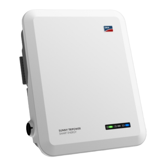
DC load-break switch LEDs The LEDs indicate the operating state of the product. Label with QR Code for scanning via the SMA 360° App and easy connec- tion to the inverter's user interface via WLAN Type label The type label clearly identifies the product. The type label must remain per- manently attached to the product. -
Page 19: Symbols On The Product
SMA Solar Technology AG 4 Product Overview Symbols on the Product Icon Explanation Beware of a danger zone This symbol indicates that the product must be additionally grounded if addi- tional grounding or equipotential bonding is required at the installation site. -
Page 20: Interfaces And Functions
4 Product Overview SMA Solar Technology AG Icon Explanation WEEE designation Do not dispose of the product together with the household waste but in accor- dance with the disposal regulations for electronic waste applicable at the in- stallation site. The product is suitable for outdoor installation. - Page 21 There is a QR code on the product by default. By scanning the QR Code attached to the product via the SMA 360° app or SMA Energy app, access to the product is established via Wi-Fi and the connection to the user interface is made automatically.
- Page 22 With SMA ShadeFix, inverters use the best possible energy supply from the PV modules at all times to increase yields in shaded systems. SMA ShadeFix is enabled by default. The time interval of SMA ShadeFix is usually six minutes. This means that the inverter determines the optimum operating point every six minutes.
-
Page 23: Led Signals
SMA Smart Connected SMA Smart Connected is the free monitoring of the product via the SMA Sunny Portal. Thanks to SMA Smart Connected, the operator and qualified person will be informed automatically and proactively about product events that occur. - Page 24 4 Product Overview SMA Solar Technology AG LED signal Explanation Red LED is flashing (0.25 s Warning on, 0.25 s off, 0.25 s on, Communication with a higher-level plant controller has failed. The in- 1.25 s off) verter continues to operate with restricted function (e.g. with set fall- back level).
-
Page 25: Battery Management
SMA Solar Technology AG 4 Product Overview Battery Management 100 % Figure 3: State of charge ranges of the battery Range Parameter Hybrid inverter behavior The hybrid inverter uses the battery within this range for increased self-consumption. When more energy is needed than can be supplied by the PV modules, the battery is discharged. -
Page 26: Sma Energy System Home
SMA Solar Technology AG SMA Energy System Home System Components The Sunny Tripower Smart Energy is part of the SMA Energy System Home. For more information on the SMA Energy System Home and the individual components, see www.SMA-Solar.com. S U N... - Page 27 The SMA EV Charger is an AC charging station that is designed for unidirectional charg- ing of a vehicle. The SMA EV Charger along with the Sunny Home Manager 2.0 makes an intelligent charging station that can charge your vehicle depending on the available solar power.
-
Page 28: System Overview
5 SMA Energy System Home SMA Solar Technology AG System Overview SUNNY PORTAL UTILITY GRID ENERGY APP 360° APP UTILITY METER FOR BILLING CONTROLLABLE PV MODULES PURPOSES INTERNET LOADS RADIO- NON- HYBRID SUNNY HOME BACKUP CONTROLLED CONTROLLABLE INVERTER MANAGER 2.0... -
Page 29: Circuitry Overview
SMA Solar Technology AG 5 SMA Energy System Home Circuitry Overview UTILITY GRID SUNNY Grid L2 L1 House connection box PORTAL ROUTER GRID-CONNECTION POINT with energy meter of the electric utility company L2 L1 N PE Grid Distribution SMA ENERGY METER / SUNNY HOME MANAGER 2.0... - Page 30 5 SMA Energy System Home SMA Solar Technology AG UTILITY GRID SUNNY Grid L2 L1 House connection box PORTAL ROUTER GRID-CONNECTION POINT with energy meter of the electric utility company L2 L1 N PE Grid Distribution SMA ENERGY METER / SUNNY HOME MANAGER 2.0...
- Page 31 SMA Solar Technology AG 5 SMA Energy System Home UTILITY GRID SUNNY L2 L1 Grid House connection box PORTAL ROUTER GRID-CONNECTION POINT with energy meter of the electric utility company Grid L2 L1 N PE Distribution SMA ENERGY METER / SUNNY HOME MANAGER 2.0...
-
Page 32: Communication Overview
5 SMA Energy System Home SMA Solar Technology AG Communication Overview SMA 360° APP SUNNY PORTAL SMA Energy APP INTERNET ROUTER SUNNY HOME MANAGER/ PV INVERTER SMA ENERGY METER SWITCH SUNNY TRIPOWER SMART ENERGY BATTERY Public Internet Ethernet LAN Radio... -
Page 33: Mounting
SMA Solar Technology AG 6 Mounting Mounting Requirements for Mounting Requirements for the mounting location: WARNING Danger to life due to fire or explosion Despite careful construction, electrical devices can cause fires. This can result in death or serious injury. - Page 34 6 Mounting SMA Solar Technology AG Dimensions for mounting: 107.4 114.3 86.2 Ø 10 10 x 13 Figure 11: Position of the anchoring points(Dimensions in mm) Recommended clearances: If you maintain the recommended clearances, adequate heat dissipation will be ensured. Thus, you will prevent power reduction due to excessive temperature.
-
Page 35: Mounting The Product
SMA Solar Technology AG 6 Mounting Figure 12: Recommended clearances(Dimensions in mm) Mounting the product Additionally required mounting material (not included in the scope of delivery): ☐ 3 screws, suitable for the support surface and the weight of the inverter (diameter: minimum 6 mm) - Page 36 6 Mounting SMA Solar Technology AG 3. Insert screw anchors into the drill holes if the support surface requires them. 4. Secure the wall mounting bracket horizontally using screws and washers. 5. Hook the inverter into the wall mounting bracket. To...
-
Page 37: Electrical Connection
SMA Solar Technology AG 7 Electrical Connection Electrical Connection Overview of the Connection Area Figure 13: Connection areas at the bottom of the inverter Position Designation 1 positive and 1 negative DC connector (type: Sunclix), input A 1 positive and 1 negative DC connector (type: Sunclix) for Sunny Tripower 5.0 SE, 6.0 SE and 8.0 SE, 2 positive and 2 negative DC connectors (type:... -
Page 38: Connecting The Grounding
100 mA or higher (see Technical Information "Criteria for Selecting a Residual-Current Device" in www.SMA-Solar.com for information on how to select a residual-current device). Each inverter in the system must be connected to the utility grid via a separate residual-current device. -
Page 39: Connecting The Inverter To The Utility Grid
SMA Solar Technology AG 7 Electrical Connection Procedure: 1. Strip the insulation of the grounding cable. Attach the ring terminal lug to the stripped wire using the required crimping tool. 2. Tighten the screw with washer and spring washer at one of the two connection points for the additional grounding (PH2, torque: 1.5 Nm). - Page 40 7 Electrical Connection SMA Solar Technology AG 6. For a cable diameter of ≥ 19 mm, remove the inner sealing ring from the AC connector. 7. Route the AC cable through the swivel nut and connector enclosure. 8. Dismantle the AC cable (80 mm to 90 mm).
- Page 41 SMA Solar Technology AG 7 Electrical Connection 14. Remove the protective cap from the AC-GRID socket. 15. Insert the AC connector into the AC-GRID socket. The AC connector must snap audibly into place. click 16. Slide the fuse terminal block onto the bracket of the AC connector from the left and screw tight (PH1, torque: 0.5 Nm).
-
Page 42: Connecting The Battery-Backup Appliances
7 Electrical Connection SMA Solar Technology AG 7.2.4 Connecting the Battery-Backup Appliances Backup loads, that are supplied from the battery in the event of a power outage, can be connected to the inverter. DANGER Danger to life due to electric shock when touching live system components... - Page 43 SMA Solar Technology AG 7 Electrical Connection 6. Unscrew the swivel nut of the AC connector and remove the terminal from the AC connector. 7. For a cable diameter of ≥ 19 mm, remove the inner sealing ring from the AC connector.
- Page 44 7 Electrical Connection SMA Solar Technology AG 15. Tighten the swivel nut on the connector enclosure. 16. Remove the protective cap from the AC-BACKUP socket. 17. Insert the AC connector into the AC-BACKUP click socket. The AC connector must snap audibly into place.
-
Page 45: Mounting The Wlan Antenna
SMA Solar Technology AG 7 Electrical Connection Mounting the WLAN Antenna The Wi-Fi antenna must be mounted. Otherwise, the degree of protection of the product cannot be guaranteed. Requirement: ☐ The Wi-Fi antenna supplied must be used. Procedure: 1. Disconnect the product from voltage sources (see Section 10, page 86). - Page 46 7 Electrical Connection SMA Solar Technology AG Additionally required material (not included in the scope of delivery): ☐ One or two network cables Network cable requirements: The cable length and quality affect the quality of the signal. Observe the following cable requirements: ☐...
-
Page 47: Connect The Communication
SMA Solar Technology AG 7 Electrical Connection 6. Insert the network plug of cable into the product's network port. Ensure that the cable is correctly locked in place. Turn the threaded sleeve onto the thread of the network port on the product. - Page 48 7 Electrical Connection SMA Solar Technology AG BMS/CAN 1 3 5 7 9 1 3 5 7 9 11 13 15 17 11 13 15 17 2 4 6 8 10 12 14 16 18 2 4 6 8 10 12 14 16 18...
-
Page 49: Connecting The Com Connector
SMA Solar Technology AG 7 Electrical Connection 7.5.2 Connecting the COM Connector 1. Disconnect the AC and backup miniature circuit breaker from all 3 line conductors and secure against reconnection. 2. Ensure that the DC load-break switch has been switched off and secured against reconnection. -
Page 50: Connecting Can Communication Cable
7 Electrical Connection SMA Solar Technology AG 11. Tighten the swivel nut. 12. Remove the protective cap from the CAN & DIG-I/ O socket. 13. Insert the connector for battery communication connection into the CAN & DIG-I/O socket. The connector must snap audibly into place on both sides. -
Page 51: Connecting Signal Source To Digital Input
SMA Solar Technology AG 7 Electrical Connection Procedure: 1. Remove 1 sealing plug from the cable support sleeve. 2. Lead the communication cable through the swivel nut and threaded sleeve. 3. Strip the communication cable 40 mm to 50 mm. 4. Trim the cable shield to a length of 15 mm and fold it over the cable sheath. - Page 52 7 Electrical Connection SMA Solar Technology AG • UV-resistant for outdoor use. Requirements: ☐ The signal source must be technically suitable for connection to the digital inputs (see Section 16, page 122). ☐ The connected digital signal source has a safe separation to the grid potential.
-
Page 53: Connecting The Multifunction Relay
SMA Solar Technology AG 7 Electrical Connection 7.5.5 Connecting the Multifunction Relay 7.5.5.1 Procedure for connecting the multifunction relay Procedure Select for which operating mode you would like to use the Section 9.13, page 79 multifunction relay. Connect to the multifunction relay according to the operat- Section 7.5.5.2, page 53... -
Page 54: Connection Of Pv Modules
7 Electrical Connection SMA Solar Technology AG Connection of PV Modules 7.6.1 Requirements for the DC Connection Connection options: The inverter has 2 DC inputs. In case of STP5.0-3SE-40 / STP6.0-3SE-40 / STP8.0-3SE-40, 1 string can be connected to DC input A and 1 string can be connected to DC input B. In case of STP10.0-3SE-40, 1 string can be connected to DC input A and 2 strings to DC input B. -
Page 55: Assembling The Dc Connectors
SMA Solar Technology AG 7 Electrical Connection ☐ All PV modules should be aligned and tilted identically. ☐ On the coldest day based on statistical records, the open-circuit voltage of the PV array must never exceed the maximum input voltage of the inverter. - Page 56 7 Electrical Connection SMA Solar Technology AG NOTICE Destruction of the inverter due to overvoltage If the open-circuit voltage of the PV modules exceeds the maximum input voltage of the inverter, the inverter can be destroyed due to overvoltage. • If the open-circuit voltage of the PV modules exceeds the maximum input voltage of the inverter, do not connect any strings to the inverter and check the design of the PV system.
-
Page 57: Connecting The Pv Array
SMA Solar Technology AG 7 Electrical Connection ☑ The stranded wire can be seen inside the clamping bracket chamber. 4. If the stranded wire is not visible in the chamber, the cable is not correctly inserted and the connector must be reassembled. To do this, the cable must be removed from the connector. - Page 58 7 Electrical Connection SMA Solar Technology AG NOTICE Destruction of the inverter due to overvoltage If the open-circuit voltage of the PV modules exceeds the maximum input voltage of the inverter, the inverter can be destroyed due to overvoltage. • If the open-circuit voltage of the PV modules exceeds the maximum input voltage of the inverter, do not connect any strings to the inverter and check the design of the PV system.
- Page 59 SMA Solar Technology AG 7 Electrical Connection 6. Check whether the DC connectors have the correct polarity. If the DC connector is equipped with a DC cable of the wrong polarity, the DC connector must be reassembled. The DC cable must always have the same polarity as the DC connector.
-
Page 60: Disassembling The Dc Connectors
7 Electrical Connection SMA Solar Technology AG 7.6.4 Disassembling the DC Connectors To disassemble the DC connectors for connection to the pv modules (e.g. due to faulty assembly), proceed as follows. DANGER Danger to life due to electric shock when touching exposed DC conductors or... -
Page 61: Connecting The Power Cable Of The Battery
SMA Solar Technology AG 7 Electrical Connection 5. Release the clamping bracket. To do so, insert a flat- blade screwdriver (blade width: 3.5 mm) into the clamping bracket and pry the clamping bracket open. 6. Remove the cable. Connecting the power cable of the battery... -
Page 62: Commissioning
8 Commissioning SMA Solar Technology AG Commissioning Commissioning Procedure This section describes the commissioning procedure and gives an overview of the steps you must perform in the prescribed order. Carry out the commissioning procedure as described in the enclosure If your product was supplied with a supplementary sheet in addition to the quick reference guide, perform commissioning according to the description in the supplementary sheet. -
Page 63: Commissioning The Inverter
SMA Solar Technology AG 8 Commissioning Commissioning the Inverter Requirements: ☐ The AC circuit breaker must be correctly rated and mounted. ☐ The product must be correctly mounted. ☐ All cables must be correctly connected. ☐ The Wi-Fi antenna must be mounted. - Page 64 On the Configuring the Inverter page, different configuration options are available to choose from. Select one of the options and proceed for the selected option as described below. SMA Solar Technology AG recommends carrying out the configuration with the installation assistant. This way, you ensure that all relevant parameters are set for optimal inverter operation.
- Page 65 SMA Solar Technology AG 8 Commissioning Adopting the Configuration from a File You can adopt the inverter configuration from a file. To do this, there must be an inverter configuration saved to a file. Procedure: 1. Select the configuration option Adopting configuration from a file.
-
Page 66: Operation
Web browser signals a security vulnerability After the IP address has been entered, a message might appear indicating that the connection to the user interface of the product is not secure. SMA Solar Technology AG guarantees the security of the user interface. -
Page 67: Establishing A Connection Via Ethernet In The Local Network
☐ An user account for Sunny Portal must already exist. Procedure: 1. Open the SMA 360° App and login with the Sunny Portal account details. 2. Select QR-Code Scan in the menu. 3. Scan the QR Code on you product via the SMA 360° App. -
Page 68: Establishing A Connection Via Wlan In The Local Network
Web browser signals a security vulnerability After the IP address has been entered, a message might appear indicating that the connection to the user interface of the product is not secure. SMA Solar Technology AG guarantees the security of the user interface. -
Page 69: Logging In And Out Of The User Interface
4. Click on Save. 5. In the New password field, enter a password for the Installer user group. Assign a uniform password to all SMA devices to be registered in a system. The installer password is also the system password. - Page 70 9 Operation SMA Solar Technology AG 3. Enter the password in the field Password. 4. Select Login. ☑ The start page of the user interface opens. Log Out as the User or Installer 1. On the right-hand side of the menu bar, select the menu User Settings.
-
Page 71: Start Page Design Of The User Interface
SMA Solar Technology AG 9 Operation Start Page Design of the User Interface Figure 20: Design of the user interface's home page (example) Operating Manual STPx0-3SE-40-BE-en-10... - Page 72 • Starting the installation assistant • Activating and Deactivating the Smart Inverter Screen • Logout Help Provides the following functions: • Displaying information on Open Source licenses used • Link to the website of SMA Solar Technology AG STPx0-3SE-40-BE-en-10 Operating Manual...
-
Page 73: Displaying And Downloading The Stored Data
SMA Solar Technology AG 9 Operation Position Designation Description Status bar Displays the following information: • Inverter serial number • Inverter firmware version • IP address of the inverter within the local network and/or IP address of the inverter during WLAN connection •... -
Page 74: Activating The Smart Inverter Screen
9 Operation SMA Solar Technology AG 3. Select the menu Data. 4. Select the folder Data. 5. To call up the data, select the respective folder and click on the required file. 6. To download the data, select the data type to be exported in the drop-down list. Then apply the time filter and select Data export. -
Page 75: Switching Wlan On And Off
SMA Solar Technology AG 9 Operation Layout of the installation assistant Figure 21: Layout of the installation assistant (example) Position Designation Description Configuration steps Overview of the installation assistant steps. The number of steps depends on the type of device and the additionally installed modules. -
Page 76: Changing The Password
9 Operation SMA Solar Technology AG The basic procedure for changing operating parameters is explained in another section (see Section 9.9, page 76). Switching WLAN Off If you would like to switch the WLAN function off completely, you must switch off both the direct connection and the connection in the local network. -
Page 77: Configuring The Country Data Set
SMA Solar Technology AG 9 Operation This section describes the basic procedure for changing operating parameters. Always change operating parameters as described in this section. Some function-sensitive parameters can only be viewed by qualified persons. Requirements: ☐ Changes to grid-relevant parameters must be approved by the responsible grid operator. -
Page 78: Set Reactive And Active Power Characteristic Curves
9 Operation SMA Solar Technology AG 4. Select [Save and continue] after each step up until the step Grid management service. 5. Make the settings as described in the following. Make the settings for systems with external setpoint 1. In the tab Active power mode set the switch Active power setpoint to [On]. -
Page 79: Setting The P(V) Characteristic Curve
SMA Solar Technology AG 9 Operation Procedure: 1. Set the parameter Number of used interpolation points in the parameter group System and device control > Inverter > Reactive power mode > Q(V) characteristic curve > Characteristic curve. 2. Set the values for the interpolation points. -
Page 80: Changing The Operating Mode Of The Multifunction Relay
The multifunction relay controls an external fan, depending on the temperature of the inverter. If the temperature of the inverter rises above a limiting value defined by SMA, the fan starts automatically. If the temperature falls below the limiting value, the fan is switched off again. -
Page 81: Power Supply Of Backup Loads In Parallel Grid Operation
> Areas of application. The value indicates the percentage of battery charge to be retained for battery-backup operation. This battery charge cannot be used in parallel grid operation. SMA Solar Technology AG recommends to set a value between 10 and 30. 9.16 Power Supply of Backup Loads in Parallel Grid... -
Page 82: Configuring The Modbus Function
The Modbus interface is deactivated by default and the communication ports 502 set. ® ® ® In order to access SMA inverters with SMA Modbus or SunSpec Modbus , the Modbus interface must be enabled. After enabling the interface, the communication ports of both IP protocols can be changed. -
Page 83: Setting Sma Shadefix
Section 9.9, page 76). Procedure: • In the parameter group DC-side > DC settings > SMA ShadeFix, set the parameter Time interval of SMA ShadeFix and set the required time interval. The ideal time interval is usually 6 minutes. This value should only be increased if the shading situation changes extremely slowly. -
Page 84: Activating Automatic Firmware Update
Update the firmware with the existing update file via the user interface of the inverter. Requirements: ☐ An update file with the desired firmware of the product must be available. You can download the update file from the product page under www.SMA-Solar.com. STPx0-3SE-40-BE-en-10 Operating Manual... - Page 85 SMA Solar Technology AG 9 Operation Procedure: 1. Open the user interface (see Section 9.1, page 66). 2. Log into the user interface as an Installer (see Section 9.2, page 69). 3. Select the menu Device Configuration. 4. In the product row, click on the gear icon and select Update firmware.
-
Page 86: Disconnecting The Inverter From Voltage Sources
10 Disconnecting the Inverter from Voltage Sources SMA Solar Technology AG 10 Disconnecting the Inverter from Voltage Sources Prior to performing any work on the product, always disconnect it from all voltage sources as described in this section. Always adhere to the prescribed sequence. - Page 87 SMA Solar Technology AG 10 Disconnecting the Inverter from Voltage Sources DANGER Danger to life due to electric shock when touching exposed DC conductors or DC plug contacts if the DC connectors are damaged or loose The DC connectors can break or become damaged, become free of the DC cables, or no longer be connected correctly if the DC connectors are released and disconnected incorrectly.
- Page 88 10 Disconnecting the Inverter from Voltage Sources SMA Solar Technology AG 11. Ensure that no electric currents are present between the positive terminal and negative terminal at the battery inputs using a suitable measuring device. 12. Insert an MC4 wrench (not included in the scope of...
- Page 89 SMA Solar Technology AG 10 Disconnecting the Inverter from Voltage Sources 16. Remove the screw of the fuse terminal of the AC connector for connecting the utility grid (PH1) and slide the fuse terminal to the left. 17. Squeeze the tabs on the top and bottom of the AC connector for connecting the utility grid and apply slight pressure.
-
Page 90: Clean The Product
11 Clean the product SMA Solar Technology AG 11 Clean the product NOTICE Damage to the product due to cleaning agents The use of cleaning agents may cause damage to the product and its components. • Clean the product and all its components only with a cloth moistened with clear water. -
Page 91: Troubleshooting
Installer is the same as the system password in the communication product. Procedure: 1. Request PUK (application form available at www.SMA-Solar.com). 2. Open the user interface (see Section 9.1, page 66). 3. Enter the PUK instead of the password into the field Password. -
Page 92: Event Messages
12 Troubleshooting SMA Solar Technology AG 12.2 Event Messages Event number Message, cause and corrective measures Grid incident The grid voltage or grid impedance at the connection point of the inverter is too high. The inverter has disconnected from the utility grid. - Page 93 SMA Solar Technology AG 12 Troubleshooting Event number Message, cause and corrective measures Grid incident The grid frequency is not within the permissible range. The inverter has discon- nected from the utility grid. Corrective measures: • If possible, check the grid frequency and observe how often fluctuations occur.
- Page 94 12 Troubleshooting SMA Solar Technology AG Event number Message, cause and corrective measures 1416 Grid incident Due to a voltage imbalance between the line conductors, the system discon- nects from the utility grid. Corrective measures: • Eliminate any faults in the installation.
- Page 95 SMA Solar Technology AG 12 Troubleshooting Event number Message, cause and corrective measures 3800 3801 DC overcurrent > Check PV array 3802 Overcurrent at the DC input. The inverter briefly interrupts feed-in operation. 3803 Corrective measures: 3804 • If this message is displayed frequently, ensure that the PV array has been 3805 correctly rated and wired.
- Page 96 12 Troubleshooting SMA Solar Technology AG Event number Message, cause and corrective measures 6201 6202 Self-diagnosis > Device disturbance 6204 The cause must be determined by the Service. 6304 Corrective measures: 6305 • Contact the Service. 6306 6313 6404 6405...
- Page 97 SMA Solar Technology AG 12 Troubleshooting Event number Message, cause and corrective measures 6513 Self-diagnosis > Overtemperature The inverter has switched off due to excessive temperature. Corrective measures: • Ensure that the airflow is free of dirt. • Ensure that the ambient temperature does not exceed the maximum permissible temperatures.
- Page 98 12 Troubleshooting SMA Solar Technology AG Event number Message, cause and corrective measures 6701 6702 Communication failure Error in the communication processor, the inverter continues feeding in, how- ever. The cause must be determined by the Service. Corrective measures: • If this message is displayed frequently, contact the Service.
- Page 99 SMA Solar Technology AG 12 Troubleshooting Event number Message, cause and corrective measures 7324 Wait for update conditions The testing of the update conditions was not successful. The firmware update package is not suitable for this inverter. Corrective measures: • Retry update.
- Page 100 12 Troubleshooting SMA Solar Technology AG Event number Message, cause and corrective measures 7340 Update communication failed Corrective measures: • Retry update. • Ensure that the selected update file is suitable for this inverter. • If this message is displayed again, contact the Service.
- Page 101 Corrective measures: • Retry update. • If this message is displayed again, contact the Service. 7359 Update BUC The SMA Backup Unit Controller that is installed in the automatic transfer switch has been updated successfully. 7360 Update BUC failed Corrective measures: •...
- Page 102 12 Troubleshooting SMA Solar Technology AG Event number Message, cause and corrective measures 7500 Sensor fault Measurement error. Corrective measures: • Contact the Service. 7600 Self-diagnosis > Communication error Corrective measures: • Contact the Service. 7613 Communication with meter faulty > Check communication to meter Communication with an energy meter is faulty.
- Page 103 SMA Solar Technology AG 12 Troubleshooting Event number Message, cause and corrective measures 8903 8904 Self-diagnosis > Device disturbance 8905 The cause must be determined by the Service. Corrective measures: • Contact the Service. 9301 New battery detected 9307 Battery system defective Corrective measures: •...
- Page 104 12 Troubleshooting SMA Solar Technology AG Event number Message, cause and corrective measures 9315 Battery imbalancing fault Corrective measures: • Contact the battery manufacturer. 9316 Internal battery hardware fault Corrective measures: • Contact the battery manufacturer. 9334 Battery charging test The battery test for charging the battery is carried out.
- Page 105 SMA Solar Technology AG 12 Troubleshooting Event number Message, cause and corrective measures 9346 Battery not configured Corrective measures: • Start the installation assistant on the inverter user interface and perform the battery configuration. 9347 Battery |b0| reports event: 0x|x5||x4|, 0x|x7||x6|, 0x|x9||x8|,...
- Page 106 12 Troubleshooting SMA Solar Technology AG Event number Message, cause and corrective measures 10109 Time adjusted / new time 10110 Time synchronization failed: |tn0| No time information could be called up from the set NTP server. Corrective measures: • Ensure that the NTP server was configured correctly.
- Page 107 SMA Solar Technology AG 12 Troubleshooting Event number Message, cause and corrective measures 10251 [Interface]: communication status goes to [OK / Warning / Error / Not connected] The communication status to the network switch or DHCP server (router) has changed. An additional error message may be displayed.
- Page 108 12 Troubleshooting SMA Solar Technology AG Event number Message, cause and corrective measures 10255 [Interface]: Network load OK The network load has returned to a normal range after being busy. 10270 No communication with SHM > Check connection The inverter is not receiving any data from the Sunny Home Manager.
- Page 109 • Ensure that the following ports are not blocked: – Registrar: ied.sma.de:9523 – Proxy: ied.sma.de:9523 – Stun: stun.sma.de:3478 – Domain: ied.sma.de (for SIP URI) 10343 Webconnect error: Default gateway not configured It is likely that there is an error in the network settings.
- Page 110 • Ensure that the following ports are not blocked: – Registrar: ied.sma.de:9523 – Proxy: ied.sma.de:9523 – Stun: stun.sma.de:3478 – Domain: ied.sma.de (for SIP URI) 10345 No reply to DNS request It is likely that there is an error in the network settings.
- Page 111 SMA Solar Technology AG 12 Troubleshooting Event number Message, cause and corrective measures 10520 Supplied power: [xx] W (permitted value: [xx] W) The set active power limitation cannot be met. Corrective measures: • Ensure that the correct active power limitation has been configured.
-
Page 112: Checking The Pv System For Ground Faults
12 Troubleshooting SMA Solar Technology AG Event number Message, cause and corrective measures 29004 Grid parameter unchanged Changing the grid parameters is not possible. 29006 Self-test 29253 Input power for backup too low The input power is too low. The battery-backup operation cannot be started. - Page 113 SMA Solar Technology AG 12 Troubleshooting WARNING Danger to life due to electric shock from destruction of the measuring device due to overvoltage Overvoltage can damage a measuring device and result in voltage being present in the enclosure of the measuring device. Touching the live enclosure of the measuring device results in death or lethal injuries due to electric shock.
- Page 114 12 Troubleshooting SMA Solar Technology AG Location of the ground fault The example shows a ground fault between the second and third PV module. V = 200 V V = 300 V 100 V 100 V 100 V 100 V...
- Page 115 40 MOhm and for polycrystalline and monocrystalline PV modules approximately 50 MOhm per PV module (for further information on calculating the insulation resistance see the Technical Information "Insulation Resistance (Riso) of Non-Galvanically Isolated PV Systems" at www.SMA-Solar.com). Required devices: ☐ Suitable device for safe disconnection and short-circuiting ☐...
-
Page 116: Problems With Streaming Services
12 Troubleshooting SMA Solar Technology AG 12. Recommission the inverter. 13. If the inverter still displays an insulation error, contact the Service (see Section 17, page 129). The PV modules might not be suitable for the inverter in the present quantity. 12.4 Problems with streaming services If you use the streaming service in your local network (in which the inverter is also included), there may be interference to the transfer of data. -
Page 117: Decommissioning The Inverter
SMA Solar Technology AG 13 Decommissioning the Inverter 13 Decommissioning the Inverter To decommission the inverter completely upon completion of its service life, proceed as described in this Section. If the inverter is defective and you have received a replacement device, observe the information on how to proceed when receiving a replacement device (see Section 15, page 121). - Page 118 13 Decommissioning the Inverter SMA Solar Technology AG 9. Unscrew and remove the antenna. 10. If there is a protective cap available, plug the protective cap onto the jack for connecting the antenna. 11. Remove connector from COM socket. 12. Remove the swivel nut from the threaded sleeve.
- Page 119 SMA Solar Technology AG 13 Decommissioning the Inverter 18. If the protective cover for the connection area is still in place, reattach the protective cover to the inverter. Otherwise, protect the connection area with another sturdy cover. 19. Remove the inverter by lifting it vertically up and off the wall mounting bracket.
-
Page 120: Procedure When Replacing A Battery
14 Procedure when Replacing a Battery SMA Solar Technology AG 14 Procedure when Replacing a Battery When a connected battery is replaced by a new battery, the battery configuration must be performed. Procedure: 1. Disconnect the inverter from all voltage sources (see Section 10, page 86). -
Page 121: Procedure For Receiving A Replacement Device
4. If the defective product had been registered by a communication product, replace it with the new product in the communication product (see operating manual of communication product). 5. Pack the defective product in the packaging of the replacement device and arrange with SMA Solar Technology AG for it to be picked up. -
Page 122: Technical Data
16 Technical Data SMA Solar Technology AG 16 Technical Data AC terminal STP5.0-3SE-40 STP6.0-3SE-40 STP8.0-3SE-40 STP10.0-3SE-40 Rated power at 5000 W 6000 W 8000 W 10000 W 230 V, 50 Hz Maximum appar- 5000 VA 6000 VA 8000 VA 10000 VA ent power at cos φ = 1 Rated apparent 5000 VA 6000 VA 8000 VA 10000 VA... - Page 123 SMA Solar Technology AG 16 Technical Data STP5.0-3SE-40 STP6.0-3SE-40 STP8.0-3SE-40 STP10.0-3SE-40 Power factor at rated power Displacement 0.8 overexcited to 0.8 overexcited to 0.8 overexcited to 0.8 overexcited to power factor 0.8 underexcited 0.8 underexcited 0.8 underexcited 0.8 underexcited cos φ, adjustable Feed-in phases Connection phases Grid configura- TN-C, TN-S, TN-C, TN-S, TN-C, TN-S,...
- Page 124 16 Technical Data SMA Solar Technology AG STP5.0-3SE-40 STP6.0-3SE-40 STP8.0-3SE-40 STP10.0-3SE-40 Maximum usable 12.5 A 12.5 A 12.5 A 25 A input current at In- put B Maximum short- 20 A 20 A 20 A 20 A circuit current / In- put A Maximum short- 20 A 20 A 20 A 40 A...
- Page 125 Available Grid monitoring Available Warning! Danger of fire due to use of non-approved batteries. Only use batteries approved by SMA Solar Technology AG (technical information with list of approved batteries at www.SMA-Solar.com). Depending on the configured country data set Operating Manual...
- Page 126 16 Technical Data SMA Solar Technology AG Maximal output overcurrent protection 32 A All-pole sensitive residual-current monitoring unit Available Overvoltage protection DC Type II / AC Type II Active anti-islanding method Frequency shift General Data Width x height x depth 500 mm x 598 mm x 173 mm Weight 30 kg...
- Page 127 SMA Solar Technology AG 16 Technical Data Wi-Fi range in free-field conditions 100 m Quantity maximum detectable Wi-Fi networks Climatic Conditions Installation in accordance with IEC 60721-3-4, Class 4K26 Extended temperature range -25°C to +60°C Extended humidity range 0% to 100% Extended air pressure range 79.5 kPa to 106 kPa...
- Page 128 16 Technical Data SMA Solar Technology AG Multifunction relay Maximum DC switching voltage 30 V Maximum AC switching current 1.0 A Maximum DC switching current 1.0 A Minimum load 0.1 W Minimum electrical endurance when the maxi- 100000 switching cycles mum switching voltage and maximum switching...
-
Page 129: Contact
SMA Solar Technology AG 17 Contact 17 Contact If you have technical problems with our products, please contact the SMA Service Line. The following data is required in order to provide you with the necessary assistance: • Device type • Serial number •... -
Page 130: Eu Declaration Of Conformity
(L 174/88, June 8, 2011) and 2015/863/EU (L 137/10, March 31, 2015) (RoHS) SMA Solar Technology AG confirms herewith that the products described in this document are in compliance with the fundamental requirements and other relevant provisions of the above- mentioned directives. The entire EU Declaration of Conformity can be found at www.SMA- Solar.com. -
Page 131: Declaration Of Conformity
• The Restriction of the Use of Certain Hazardous Substances in Electrical and Electronic Equipment Regulations 2012 SMA Solar Technology AG confirms herewith that the products described in this document are in compliance with the fundamental requirements and other relevant provisions of the above- mentioned regulations. - Page 132 www.SMA-Solar.com...
Need help?
Do you have a question about the SUNNY TRIPOWER 5.0 SMART ENERGY and is the answer not in the manual?
Questions and answers