Sun Microsystems StorEdge A1000 Operation And Service Manual
Hide thumbs
Also See for StorEdge A1000:
- Installation, operation and service manual (60 pages) ,
- Installation manual (17 pages) ,
- Installation manual (8 pages)
Table of Contents
Advertisement
Quick Links
Advertisement
Table of Contents

Related Manuals for Sun Microsystems StorEdge A1000


Summary of Contents for Sun Microsystems StorEdge A1000
- Page 1 A1000 and ™ ™ D1000 Installation, Operations, and Service Manual Sun Microsystems Computer Company A Sun Microsystems, Inc. Business 901 San Antonio Road Palo Alto, CA 94303-4900 USA 650 960-1300 fax 650 969-9131 Part No.: 805-2624-10 Revision A, February 1998...
- Page 2 Sun, Sun Microsystems, the Sun logo, AnswerBook, SunDocs, Solstice DiskSuite, StorEdge, and Solaris are trademarks, registered trademarks, or service marks of Sun Microsystems, Inc. in the U.S. and other countries. All SPARC trademarks are used under license and are trademarks or registered trademarks of SPARC International, Inc.
- Page 3 FCC radio frequency emission limits. Networking connections can be made using unshielded twisted-pair (UTP) cables. Modifications: Any modifications made to this device that are not approved by Sun Microsystems, Inc. may void the authority granted to the user by the FCC to operate this equipment.
- Page 4 This Class B digital apparatus meets all requirements of the Canadian Interference-Causing Equipment Regulations. Cet appareil numérique de la classe B respecte toutes les exigences du Règlement sur le matériel brouilleur du Canada. Sun StorEdge A1000 and D1000 Installation, Operations, and Service Manual • February 1998...
- Page 5 Compliance ID: 1630 Product Name: Sun StorEdge A1000,Tabletop; Sun StorEdge D1000,Tabletop This product has been tested and complies with: USA - FCC Class B This equipment complies with Part 15 of the FCC Rules. Operation is subject to the following two conditions: 1) This equipment may not cause harmful interference.
- Page 6 Sun StorEdge A1000 and D1000 Installation, Operations, and Service Manual • February 1998...
- Page 7 Modifications to Equipment Do not make mechanical or electrical modifications to the equipment. Sun Microsystems is not responsible for regulatory compliance of a modified Sun product. Safety Agency Compliance Statements...
- Page 8 Stromquellen an. Ihr Betriebsleiter oder ein Bedeutung: qualifizierter Elektriker kann Ihnen die Daten zur Stromversorgung in Ihrem Gebäude geben. Achtung – Gefahr von Verletzung und Geräteschaden. Befolgen Sie die Anweisungen. viii Sun StorEdge A1000 and D1000 Installation, Operations, and Service Manual • February 1998...
- Page 9 Systemeinheit entfernt wurde. Batterien Attention : surface à température élevée. Evitez le contact. La température des surfaces est élevée et leur Vorsicht - Die Geräte StorEdge A1000 von Sun contact peut provoquer des blessures corporelles. enthalten auslaufsichere Bleiakkumulatoren. Produkt-Nr. TLC02V50 für portable Attention : présence de tensions dangereuses.
- Page 10 En este libro aparecen los siguientes símbolos: d’alimentation lorsque le châssis du système n’est plus alimenté. Precaución – Existe el riesgo de lesiones personales y daños al equipo. Siga las instrucciones. Sun StorEdge A1000 and D1000 Installation, Operations, and Service Manual • February 1998...
- Page 11 No realice modificaciones de tipo mecánico o eléctrico en el accesible. No conecte el cable de alimentación cuando equipo. Sun Microsystems no se hace responsable del se ha retirado la fuente de alimentación del chasis del cumplimiento de las normativas de seguridad en los equipos sistema.
- Page 12 GOST-R Certification Mark Z001 Sun StorEdge A1000 and D1000 Installation, Operations, and Service Manual • February 1998...
-
Page 13: Table Of Contents
Contents Preface xv Getting Started 1 SCSI Host Adapters 1 Before You Begin 1 Sun StorEdge A1000 Configurations 2 Sun StorEdge D1000 Configurations 3 Preparing and Installing the System 5 Installing the System 5 Product Overview 7 System Hardware 7... - Page 14 Sun StorEdge A1000 Hardware RAID Controller Module 13 Sun StorEdge A1000 Software 13 The Sun StorEdge D1000 Unit 14 Components at the Front of the Unit 14 Components at the Back of the Unit 15 Power Modules 18 Cooling System 18...
-
Page 15: Preface
The Sun™ StorEdge™ A1000 and D1000 Installation, Operations, and Service Manual provides installation and configuration information and service procedures to customers and service personnel for the Sun StorEdge A1000 and D1000 systems. These instructions are designed for an experienced system administrator. - Page 16 Shell Prompts Shell Prompts TABLE P-2 Shell Prompt C shell machine_name% C shell superuser machine_name# Bourne shell and Korn shell Bourne shell and Korn shell superuser Sun StorEdge A1000 and D1000 Installation, Operations, and Service Manual • February 1998...
- Page 17 Sun StorEdge D1000 Storage Guide 805-4013-10 Ordering Sun Documents SunDocs is a distribution program for Sun Microsystems technical documentation. Contact SunExpress for easy ordering and quick delivery. You can find a listing of available Sun documentation on the World Wide Web. SunExpress Contact Information...
- Page 18 You can email or fax your comments to us. Please include the part number of your document in the subject line of your email or fax message. Email: smcc-docs@sun.com xviii Sun StorEdge A1000 and D1000 Installation, Operations, and Service Manual • February 1998...
-
Page 19: Getting Started
C H A P T E R Getting Started The Sun StorEdge A1000 and D1000 systems are made up of a chassis, dual power supplies, dual cooling canisters, the controller module and from 4 to 12 hot-pluggable, UltraSCSI hard disk drives. Both the A1000 and D1000 units may be used on the desktop. -
Page 20: Sun Storedge A1000 Configurations
6. Decide which configuration to use. Sun StorEdge A1000 Configurations You can use the Sun StorEdge A1000 Hardware RAID controller as a single unit connected to one or more hosts, or connect up to ten units together in a chain. For optimal performance, chain only three Sun StorEdge A1000 units together. -
Page 21: Sun Storedge D1000 Configurations
SCSI Connectors IN/OUT IN/OUT SCSI Cable to Host Terminator A Sun StorEdge A1000 in a Chained Configuration FIGURE 1-2 Sun StorEdge D1000 Configurations You can use the Sun StorEdge D1000 unit in several different configurations. As a single box of disks attached to a single host (... - Page 22 A Single Sun StorEdge D1000 Split Between Two Hosts FIGURE 1-4 A single unit split between two hosts, where each host has access to half the disks FIGURE 1-4 Sun StorEdge A1000 and D1000 Installation, Operations, and Service Manual • February 1998...
-
Page 23: Preparing And Installing The System
You must perform the following tasks to prepare and install your Sun StorEdge A1000 or D1000 system. 1. Set up your Sun StorEdge A1000 or D1000 with the mounting hardware, if any, that came with your system. 2. Determine which SCSI target addresses are available on your host system. - Page 24 3. Connect the cables and power cords. Use only UltraSCSI cables. 4. Install one or more terminators, depending on the configuration you have chosen. 5. Turn on the power to the Sun StorEdge A1000 or D1000 system and the host system. 6. Install any additional software.
-
Page 25: Product Overview
D1000 unit — “Just a Bunch of Disks” (JBOD) configuration Sun StorEdge A1000 Hardware RAID System The system chassis houses several removable devices, including: Sun StorEdge A1000 Hardware RAID Controller Module Two power supplies Battery Dual cooling canisters Disk drives... -
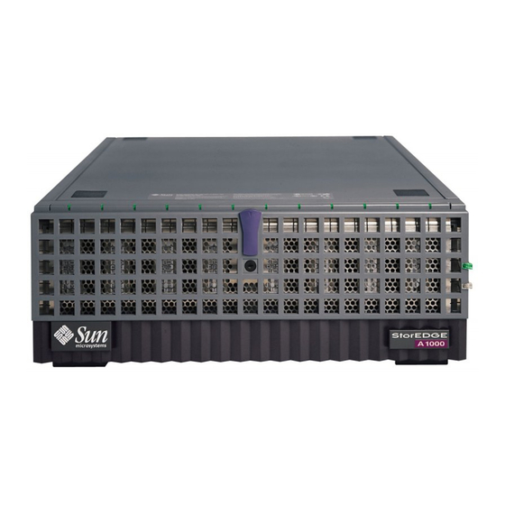
Page 26: Components At The Front Of The Unit
System Power LED Door Latch System Summary Fault LED Sun StorEdge A1000 Front — An Example of a Twelve 1-inch Drive System FIGURE 2-1 Front Door The lockable front door opens to allow access to the hard disk drives. The door keys are in the ship kit pouch. -
Page 27: Components At The Back Of The Unit
68-pin connectors for the host SCSI bus, a SCSI ID switch and a locking power switch. Power Switch The Sun StorEdge A1000 system has one rocker power switch to control both power supplies ( FIGURE 2-3 Right —... - Page 28 Battery The Sun StorEdge A1000 system has a data cache hold-up battery in the hardware RAID controller board. During a power outage, a properly charged battery will maintain electrical power to the controller’s data cache memory for up to three days.
-
Page 29: Power Modules
Off when the battery is not charging Power Modules The Sun StorEdge A1000 system has two hot-pluggable and interchangeable power supplies. The two power supplies provide power to the internal components, converting incoming AC voltage to DC voltages. These are redundant power supplies—one power supply will maintain electrical power to the system if the other... -
Page 30: Cooling System
The Sun StorEdge A1000 system has two cooling canisters. Each contains two blowers. The cooling canisters are hot-pluggable and interchangeable. The Sun StorEdge A1000 system can operate fully cooled with three of the four blowers functioning. If two blowers fail, the remaining two can maintain the system in a 30C environment, but the reliability of the components may be affected. -
Page 31: Sun Storedge A1000 Hardware Raid Controller Module
Sun StorEdge A1000 Hardware RAID Controller Module The Sun StorEdge A1000 hardware RAID controller module is a compact unit designed to provide high-performance disk array management services. The controller module supports dual SCSI hosts on a 16-bit SCSI-2 bus. There are 2 SCSI controllers inside the controller module that manage data distribution and storage for up to 12 disk drives. -
Page 32: The Sun Storedge D1000 Unit
Sun StorEdge D1000 Front — An Example of a Eight 1.6-inch Drive System FIGURE 2-4 Front Door The lockable front door opens to allow access to the hard disk drives. The door keys are in the ship kit pouch. Sun StorEdge A1000 and D1000 Installation, Operations, and Service Manual • February 1998... -
Page 33: Components At The Back Of The Unit
The system backplane for the hard disk drives can accept up to eight 1.6-inch drives or twelve 1-inch drives. LEDs on the Front System Power LED: lights green when the system is powered on. Each slot for a hard disk drive has a two-color LED above the disk drive. The LED: Remains unlit when no drive is in the slot Lights green when the drive is present but not active... - Page 34 Down: check switch 4 4. Drives Delayed Start Up: start with (12 x SCSI device ID number) seconds delay (factory default) Down: start at power-on 5. Reserved (No function) Sun StorEdge A1000 and D1000 Installation, Operations, and Service Manual • February 1998...
- Page 35 Option Switch 2 Option Switch 1 SCSI Disk Array 2 SCSI Disk Array 1 Default Default Option Switch 2 Option Switch 1 Down Down Sun StorEdge D1000 SCSI Disk ID Address Assignment —12-drive system FIGURE 2-7 Option Switch 1 Option Switch 2 SCSI Disk Array 2 SCSI Disk Array 1 Default...
-
Page 36: Power Modules
The D1000 system can operate fully cooled with three of the four blowers functioning. If two blowers fail, the remaining two can maintain the system in a 30C environment, but the reliability of the components may be affected. Sun StorEdge A1000 and D1000 Installation, Operations, and Service Manual • February 1998... -
Page 37: Disk Drives
The blower speeds are variable and increase their speed to counteract unusual cooling conditions, such as one failed blower or increased internal temperature. Caution – Do not operate the system for extended periods with one or more redundant modules not installed. The cooling system will become inefficient. Disk Drives See the documentation that comes with your system for information about the drives installed in your system. -
Page 38: Sun Storedge D1000 Software Considerations
Veritas™ VxVm in a RAID based system. See the Veritas software user’s guide on your system CD. A Veritas VxVm license can be obtained from Sun. Sun StorEdge A1000 and D1000 Installation, Operations, and Service Manual • February 1998... -
Page 39: Removing And Replacing Components
C H A P T E R Removing and Replacing Components The Sun StorEdge A1000 and D1000 systems contain easy access components, some of which are hot-pluggable and some of which must be replaced with the power off. Hot-pluggable Parts... -
Page 40: Replacing Hot-Pluggable Parts
Replacing Hot-Pluggable Parts Hard Disk Drives The Sun StorEdge A1000 or D1000 system you ordered comes configured with either 1.6-inch drives or one-inch drives. The procedure for removing and replacing the drives differs only in the software you use to control the disks. In all cases the hard disks are hot-pluggable. -
Page 41: Cooling Canisters
4. Close the locking handle handle completely, using gentle downward pressure. Cooling Canisters The Sun StorEdge A1000 or D1000 comes with two cooling canisters, each of which contains two blowers. If any of the blowers fails, the LED on the back of the system lights amber, indicating which blower has failed. -
Page 42: Power Supplies
4. Close the locking handle. Power Supplies The Sun StorEdge A1000 or D1000 enclosure comes with two power supplies. The LED on the power supply lights amber when the power supply fails. Although the system can run well with only one power supply, the faulty one should be replaced in case the good one goes bad. - Page 43 To Replace a Power Supply 1. Disconnect the power cord from the power supply you intend to replace. You cannot remove the power supply without first disconnecting the power cord. . and for the positions of the power connector and locking FIGURE 3-2 FIGURE 3-3 handle.
-
Page 44: Replacing Parts With The Power Off
StorEdge A1000 and D1000 versions of the system. To Remove the Controller Board 1. Stop the software communication with the Sun StorEdge A1000 or D1000 system. See the documentation that came with your software. 2. Turn off the power to the system. - Page 45 Controller Board Levers FIGURE 3-5 5. Slide the controller board canister out and set it on an antistatic mat. a. Use the levers at each side to release the controller board. b. Hold the levers to slide the canister out. Chapter 3 Removing and Replacing Components...
-
Page 46: Battery (A1000 Only)
To Replace the Battery Replace the battery only with the same type of Sun Microsystems battery. Sun StorEdge A1000 and D1000 Installation, Operations, and Service Manual • February 1998... - Page 47 2. Push down the catch on the outside of the battery. 3. Pull the battery out. Caution – There is a sealed lead acid battery in Sun StorEdge A1000 units. There is danger of explosion if the battery pack is mishandled or incorrectly replaced.
-
Page 48: Simm Upgrade Procedure (A1000 Only)
This exposes the SIMMs ( FIGURE 3-8 4. Attach the antistatic wrist strap to your wrist and an unpainted metal part of the chassis. Sun StorEdge A1000 and D1000 Installation, Operations, and Service Manual • February 1998... - Page 49 Slot A Slot B Slot C Slot D A1000 Controller—Empty SIMM slots FIGURE 3-9 5. Remove the SIMMs and set them on an antistatic mat. Remove the SIMMs from front to back. Press the small latch on each side of the SIMM that releases it from the slot ( FIGURE 3-10 a.
- Page 50 The new part number label correctly identifies your controller upgrade. 9. Remove the antistatic strap and replace the lid to the canister. Secure the screws. 10. Replace the canister into the Sun StorEdge A1000 unit. See “To Replace the Controller Board.” Sun StorEdge A1000—SIMM Upgrade FIGURE 3-11 Sun StorEdge A1000 and D1000 Installation, Operations, and Service Manual •...
- Page 51 A P P E N D I X System Specifications Physical Specifications The outside measurements of the chassis are as follows: Width: 53.34 cm (21.0 in) Depth: 44.7 cm (17.6 in) Height: 17.78 cm (7.0 in) Weight: A1000 without disk drives: 19.3 kg (42.5 lbs) fully loaded:...
- Page 52 Requirement Max. Operating 2.6 amps Max. Surge 22 amp peaks Typical current ratings at 240 volts AC, 60 Hz. Assumes a 0.70 power efficiency, 0.99 power factor. Sun StorEdge A1000 and D1000 Installation, Operations, and Service Manual • February 1998...
- Page 53 Environmental Specifications Environmental Requirements Table A-2 Climate Control Location Minimum to Maximum Range Temperature (dry bulb) Operating 5˚C to 40˚C Storage -20˚C to 60˚C Transit -20˚C to 60˚C Operating 3.3˚C per 1000m (1.7˚F per 1000 ft) above sea Temperature Derating (max.) level Relative Humidity (non-condensing) Operating...
- Page 54 Sun StorEdge A1000 and D1000 Installation, Operations, and Service Manual • February 1998...
Need help?
Do you have a question about the StorEdge A1000 and is the answer not in the manual?
Questions and answers