Table of Contents
Advertisement
Quick Links
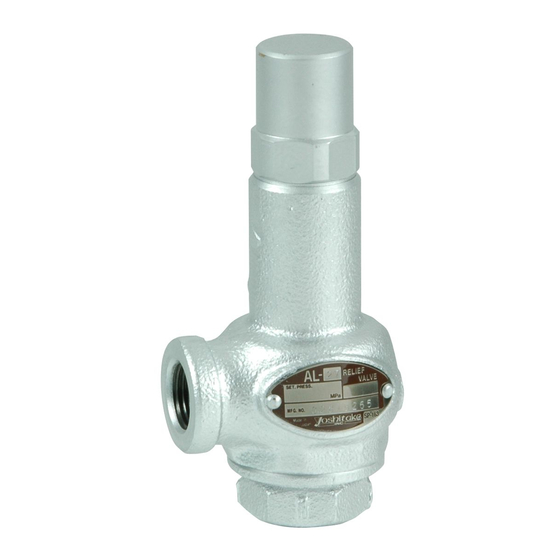
SAFETY RELIEF VALVE
Thank you very much for choosing the Yoshitake's product. To ensure the correct and safe use of the
product, please read this manual before use. This manual shall be kept with care for future references.
The symbols used in this manual have the following meanings.
Warning
Caution
1. Usage of the Product ·················································· 1
2. Specifications ···························································· 1
3. Dimensions and Weight ·············································· 2
4. Structure ································································ 3
5. Operation ······························································· 3
6. Nominal Size Selection Chart ······································· 4
7. Installation ···························································· 7-12
8. Maintenance ···························································· 12
MODEL AL-27
PRODUCT MANUAL
This symbol indicates a potentially hazardous situation that, if not avoided,
could result in death or serious injury.
This symbol indicates a hazardous situation that, if not avoided, may result in
minor or moderate injury or may result in only property damage.
7.1 Fitting pipe base ·················································· 8
7.2 Discharge pipe ···················································· 8
7.3 Set pressure adjustment ···································· 9-12
8.1 Daily inspection ·················································· 12
8.2 Periodic inspection ·············································· 12
8.3 Troubleshooting ············································· 13-14
Table of Contents
.
■EPDT-351■
Advertisement
Table of Contents

Related Manuals for Yoshitake AL-27


Summary of Contents for Yoshitake AL-27
-
Page 1: Table Of Contents
SAFETY RELIEF VALVE PRODUCT MANUAL Thank you very much for choosing the Yoshitake’s product. To ensure the correct and safe use of the product, please read this manual before use. This manual shall be kept with care for future references. -
Page 2: Usage Of The Product
1. Usage of the Product The AL-27 is a relief valve for pressure control in a pump system in which large pressure pulsation or fluctuation occurs. 2. Specifications Model AL-27 Structure Closed type Cold and hot water, Oil (heavy oil A, heavy oil B, kerosene),... -
Page 3: Dimensions And Weight
3. Dimensions and Weight Figure 1. Dimensions Table 1. Dimensions and weight (mm) Nominal Weight(kg) Size Rc 1/2 Rc 3/4 Rc 1 Rc 1 1/4 Rc 1 1/2 Rc 2 ■EPDT-351■... -
Page 4: Structure
4. Structure Outlet Inlet Figure 2. Structure Table 2. Parts list 7 Spring plate 6 Spring 13 Gasket 5 Spindle 12 Gasket 4 Valve 11 Cap 3 Valve seat 10 Lock nut 2 Body 9 Adjusting screw 1 Spring case 8 Spring plate №... -
Page 5: Nominal Size Selection Chart
6. Nominal Size Selection Chart The flow rate of each size with 25% of accumulation (excess to the set pressure) is shown in Figure 3. See Figure 4 when the accumulation is less than 25%. Fluid: Water Nominal size Opening pressure MPa Figure 3. - Page 6 Accumulation % Figure 4. Approximate flow rate magnification Figure 4 is referred to when calculating the approximate flow rate with accumulation less than 25%. Example: When calculating the flow rate of the size of 25A, with the opening pressure of 0.1 MPa, and accumuation of 20%, first, find the flow rate with the accumulation of 25% by using Figure 3.
- Page 7 Table 3. Discharge capacity (for Reference) [Accumulation: 25%] Nominal Set pressure (MPa) size 0.05 0.30 0.42 0.74 0.85 0.95 1.04 1.13 1.21 1.28 1.35 0.49 0.69 0.98 1.20 1.39 1.55 1.70 1.84 1.96 2.08 2.20 0.77 1.08 1.54 1.88 2.17 2.43 2.66 2.88...
-
Page 8: Installation
7. Installation Warning 1. Do not install any closing devices such as a stop valve at inlet or outlet side of the product. 2. Do not apply the product to equipment or devices which do not allow any valve seat leakage. 3. -
Page 9: Fitting Pipe Base
7.1 Fitting pipe base (See Figure 5.) (1) Fitting pipe base should have enough strength and rigidity against the stress induced by reaction force in the opposite direction of the exhaust through the axis of the exhaust pipe. (2) Equip the discharge pipe with a support to avoid excessive load, deflection, or vibration. (3) Install the product at a place where its maintenance and inspection can be performed. -
Page 10: Set Pressure Adjustment
7.3 Set pressure adjustment (See 4. Structure) To adjust the set pressure, remove the cap [11], make a 1/4 to 1/3 turn of the adjusting screw [9] slowly as checking the pressure gauge, and check the Warning operation each time after turning the adjusting screw [9]. Be careful not to overturn or the fluid may suddenly blow out. - Page 11 Pictures below show the product only. However, actual adjustment should be done while the product is installed on the piping. 2. Remove the cap [11] with a wrench by 1. AL-27 Safety relief valve turning it counterclockwise. The fluid leaks when the cap [11] is removed. Be careful not to get injured or Warning scalded and not to make the surroundings dirty.
- Page 12 4.2 To increase the set pressure, 4.1 To decrease the set pressure, make make a 1/4 to 1/3 turn of the a 1/4 to 1/3 turn of the adjusting adjusting screw clockwise screw [9] counterclockwise slowly slowly by a spanner or a wrench. by a spanner or a wrench.
-
Page 13: Maintenance
5. Confirm that there is no damage on the gasket [13] prior to attaching the cap [11]. if the gasket [13] is damaged, it must be replaced with a new one which is recommended to be prepared in advance. Before attaching the gasket [13], apply paste (Recommendation: SOLVEST No.110, STT Inc.) to its surfaces and its inner diameter surface, and then attach the gasket [13]. -
Page 14: Troubleshooting
2. Set pressure does not meet the 2. Check the specifications. specifications required. The product needs to be disassembled and some parts need to be replaced at Yoshitake. Please contact us. 3. The product malfunctions due to 3. See “2. Specifications” and vibration applied. “7. Installation.”... - Page 15 The product needs to be disassembled stop blowing. and some parts need to be replaced at Yoshitake. Please contact us. 2. Insufficient sliding action of valve [4]. 2. The product needs to be disassembled and the damaged parts need to be replaced by Yoshitake.
-
Page 16: Warranty Information
Fire, flood, earthquake, thunder and other natural disasters. Consumable parts such as O-ring, gasket, diaphragm and etc. Yoshitake is not liable for any damage or loss caused by malfunction or defect of the product. INTERNATIONAL DEPT. 955-5, Miyamae, Irukadeshinden, Komaki, Aichi, 485-0084, Japan...
Need help?
Do you have a question about the AL-27 and is the answer not in the manual?
Questions and answers