Table of Contents
Advertisement
Quick Links
Thank you very much for choosing the Yoshitake's product. To ensure the correct and safe use of the
product, please read this manual before use. This manual shall be kept with care for future references.
The symbols used in this manual have the following meanings
Warning
Caution
1. Usage of the Product········································ 1
2. Specifications ················································· 1
3. Dimensions and Weights ·································· 2
4. Operation ······················································· 3
Warranty information
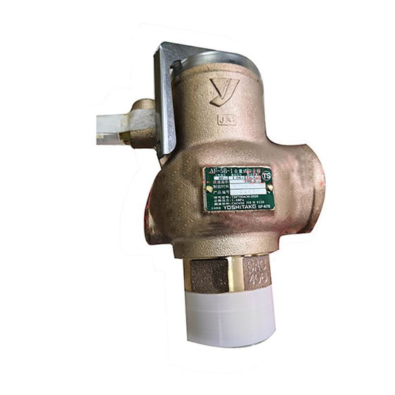
MODEL AF-5
FULL BORE SAFETY VALVE
PRODUCT MANUAL
The following safety symbols are used in this manual
This symbol indicates a potentially hazardous situation that, if not
avoided, could result in death or serious injury.
This symbol indicates a hazardous situation that, if not avoided, may
result in minor or moderate injury or may result in only property damage.
Table of Contents
5.1 Pre-warning and precaution for use ·········· 3~4
5.2 Warning for use ········································· 5
5.3 Warning for inspection ································ 5
■EPDT-072j■
Advertisement
Table of Contents

Related Manuals for Yoshitake AF-5


Summary of Contents for Yoshitake AF-5
-
Page 1: Table Of Contents
The following safety symbols are used in this manual Thank you very much for choosing the Yoshitake’s product. To ensure the correct and safe use of the product, please read this manual before use. This manual shall be kept with care for future references. -
Page 2: Usage Of The Product
1.Usage of the Product AF-5 can be used for various pressure vessels such a steam boiler, various pressure vessels, and suitable for the downstream of a pressure reducing valve instrumentation apparatus. 2.Specifications Air, Application Steam other non-dangerous fluids Structure *Open type with a lever Working pressure 0.1~2.0 MPa... -
Page 3: Dimensions And Weights
3.Dimensions and weights (㎜) Flow area Weight Nominal Lift Plug size (kg) 3.3 20 Rc 1 R 1/8 176.6 (151) (1.5) 4.4 25 R 1 1/4 Rc 1 1/4 45 R 1/8 283.3 (182) (2.1) 5.5 32 R 1 1/2 Rc 1 1/2 52 R 1/8 452.1... -
Page 4: Operation
4.Operation Blowout operation As inlet pressure approaches the blowout pressure, the force of fluid pushing up the valve [5] approaches the force of the spring [9] pressing down the valve. The safety valve commences to blow when the inlet pressure reaches around 3% below the blowout pressure. The fluid starts to leak by simmering and accumulates gradually on the valve holder . - Page 5 Caution 1. Before installing the product, remove foreign substances and scale from the piping. * Failure to follow this notice may hamper proper operation. 2. When installing the product, match the direction of fluid flow with the inlet and outlet of the product respectively.
-
Page 6: Warning For Use
5.2 Warning for use Warning 1. Please do not directly touch the product with bare hands. * Failure to follow this notice may result in scalds or injury in case that fluid is hot. 2. Please do not put your head and hands on the outlet side. * When suddenly blowing out, there is a risk of injury or burns.
Need help?
Do you have a question about the AF-5 and is the answer not in the manual?
Questions and answers