Table of Contents
Advertisement
Quick Links
Advertisement
Table of Contents

Related Manuals for Benning CM7


Summary of Contents for Benning CM7
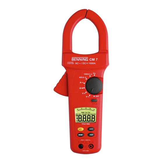
- Page 1 BENNING CM7 Electrical Tester Service Information...
-
Page 2: Table Of Contents
TABLE OF CONTENTS Page Introduction Precautions and Safety Information Symbols Safety Specifications General Specification Voltage Specification Resistance & Continuity Specification Current Specification Frequency Specification Physical and environment characteristics Certification and compliance Required Equipment Basic Maintenance Opening the Meter Case Replacing the Battery Performance Tests Testing the Voltage Function Testing the Resistance Function... -
Page 3: Introduction
The CM7 contain parts that can be damaged by static discharge. Follow the standard practices for handling static sensitive devices. For additional information about BENNING GMBH & CO. KG. and its products, and services, visit BENNING GMBH & CO. KG. web site at: www.benning.de... -
Page 4: Safety
SAFETY Review the following safety precautions to avoid injury and prevent damage to this product or products connected to it. To avoid potential hazards, use the product only as specified. CAUTION: These statements identify conditions or practices that could result in damage to the equipment or other property. -
Page 5: Specifications
SPECIFICATIONS All specifications are warranted unless noted typical and apply to the CM7. Stated accuracies are at 23°C±5°C at than 80% relative humidity and without the battery indicator displayed. General specifications Characteristics Description Display count 3 3/4 Numeric update rate 1.5 times / sec... -
Page 6: Voltage Specification
Measurement Characteristics Accuracy is ±(% reading + number of digits) at 23°C ± 5°C, less than 80% R.H. Temperature coefficient: 0.2 × (Specified accuracy) /°C, <18°C, >28°C Operating temperature: 0°C ~ 30°C (≦ 80% RH) 30°C ~ 40°C (≦ 75% RH) 40°C ~... -
Page 7: Current Specification
(4) Frequency: Hz Over voltage Range Resolution Accuracy protection AC/DC 1000A 20Hz ~ 400Hz ±(0.1% reading + 2 digits) for 1 min. Min. Input Frequency:20Hz Sensitivity: 3A rms for ACA (A~)(>400Hz Unspecified) (5) ACA: Auto-ranging Frequency Overload Range Resolution Accuracy Response protection 0A ~... - Page 8 (7) Auto Power Off (APO) The meter will automatically shut itself off after approximately 30 minutes after power on. (8) Peak Hold: ±(3% reading +20 digits) * >750V Unspecified. * >800A Unspecified. (9) Min/Max Hold: Add ± 15 dgt to accuracy for ACA. Add ±...
-
Page 9: Physical And Environment Characteristics
Physical and Environmental Characteristics Characteristics Description Dimensions (H×W×D) 51mm×90mm×275mm Weight (with battery) 420g Environmental characteristics Description Temperature operating 0 to +50°C Non-Operating -20 to +60°C Humidity (operating) <80% R.H. Altitude Operating 2,000M (6560 ft.) Non-Operating 12,300M (40354 ft.) MIL-T-28800E TYPE II Class 5 Vibration &... -
Page 10: Required Equipment
Required Equipment Required equipment is listed in Table B. If the recommended models are not available, equipment with equivalent specifications may be used. Repairs or servicing should be performed only by qualified personnel. Table B. Required Equipment Equipment Required Characteristics Recommended Model AC Voltage Range: 0 ~... -
Page 11: Basic Maintenance
3. The case bottom is secured to the case top by two screws. Using a Phillips-had screwdriver, remove the two screws. Replacing the Battery The Meter powered by 9V battery for CM7. To replace the battery refer to figure. -
Page 12: Performance Tests
Performance Tests The following performance tests verify the complete operability of the Meter and check the accuracy of each Meter function against the Meter’s specifications. Accuracy specifications are valid for a period of one year after calibration, when measured at an operating temperature of 18°C to 28°C and a maximum of 80% relative humidity. -
Page 13: Testing The Resistance Function
6. Turn the rotary switch to “V ” position. 7. Set the calibration for the voltage from step 1 to 4 in Table 2. 8. Compare the reading on the Meter display with the display reading shown in Table 2. 9. -
Page 14: Testing The Ac Current Function
Testing the AC Current Function To verify the accuracy of AC current measurement functions, do the following: 1. Using jaw of the meter around the suitable wire or conductor. 2. Turn the rotary switch to A. 3. Apply the inputs for steps 1-2 in Table 4. 4. -
Page 15: Testing The Hz Function
Testing the Hz Function To verify the accuracy of Hz current measurement functions, do the following: 1. Using jaw of the meter around the suitable wire or conductor. 2. Turn the rotary switch to Hz. 3. Apply the inputs for steps 1-2 in Table 6. 4. -
Page 16: Calibration
Calibration Procedure Recalibrate your meter: It is recommended that the meter may be calibrated once year. Use the following procedure to calibrate the clamp meter. 1. Perform calibration at an ambient temperature and a relative humidity (23ºC±2ºC and RH≦ 80% ). Allow instrument to sit at this temperature for at least thirty minutes. 2. - Page 17 (E) AC 400A Range Calibration (Adjust VR104) 1. Set the clamp meter at ACA function. 2. Flow the current of AC 360A±0.02%/50Hz around the suitable wire or conductor. 3. Position clamp around wire or conductor and release trigger to make sure the clamp is entirely closed.
Need help?
Do you have a question about the CM7 and is the answer not in the manual?
Questions and answers