Table of Contents
Advertisement
Quick Links
IMPORTANT: This is a supplemental instruction for the
48/50HJ and the 62AQ Installation, Start-Up and Service
Instructions. It is not intended to take the place of either
instruction or to be a complete piece in itself.
CONTENTS
SAFETY CONSIDERATIONS . . . . . . . . . . . . . . . . . . . . . . 1
GENERAL . . . . . . . . . . . . . . . . . . . . . . . . . . . . . . . . . . . . . . . . 1
INSTALLATION . . . . . . . . . . . . . . . . . . . . . . . . . . . . . . . . 2-29
Step 1 - Inspect Shipment . . . . . . . . . . . . . . . . . . . . . . 2
Step 2 - Provide Unit Support . . . . . . . . . . . . . . . . . . . 2
Step 3 - Field Fabricate Ductwork . . . . . . . . . . . . . . . 3
Step 4 - Rig and Place Unit . . . . . . . . . . . . . . . . . . . . . 6
•
Step 5 - Install Flue Hood (48HJ Only) . . . . . . . . . 11
Step 6 - Install Gas Piping (48HJ Only). . . . . . . . . 11
Drain. . . . . . . . . . . . . . . . . . . . . . . . . . . . . . . . . . . . . . . . . . 11
Step 8 - Make Electrical Connections . . . . . . . . . . 11
Step 9 - Assemble and Mount
Supply-Air Hood . . . . . . . . . . . . . . . . . . . . . . . . . . . . . . 28
ACCESSORY . . . . . . . . . . . . . . . . . . . . . . . . . . . . . . . 30-34
General. . . . . . . . . . . . . . . . . . . . . . . . . . . . . . . . . . . . . . . . . . 30
Power . . . . . . . . . . . . . . . . . . . . . . . . . . . . . . . . . . . . . . . . . . . 30
Thermidistat Location . . . . . . . . . . . . . . . . . . . . . . . . . 30
Step 2 - Set DIP Switches . . . . . . . . . . . . . . . . . . . . . . . 30
Configuration. . . . . . . . . . . . . . . . . . . . . . . . . . . . . . . . . . 31
Thermidistat Start-Up and Checkout . . . . . . . . . . . 33
Step 6 - Make Final Settings . . . . . . . . . . . . . . . . . . . . 34
OPERATIONAL INFORMATION . . . . . . . . . . . . . . . . . . 34
PRE-START-UP . . . . . . . . . . . . . . . . . . . . . . . . . . . . . . . . . . 35
START-UP . . . . . . . . . . . . . . . . . . . . . . . . . . . . . . . . . . . . . . . 35
SERVICE . . . . . . . . . . . . . . . . . . . . . . . . . . . . . . . . . . . . . 35-37
TROUBLESHOOTING . . . . . . . . . . . . . . . . . . . . . . . . . 38-41
ROOFTOP UNIT AND ENERGY$RECYCLER2
START-UP CHECKLIST . . . . . . . . . . . . . . . . CL-1, CL-2
PC 111
Book 1
1
4
4
Tab
1a 1b 6a 6b
Installation, Start-Up,
and Service Supplement
Page
Catalog No. 534-80122
Printed in U.S.A.
COBRA™ Energy Recovery Units
48/50HJ004-014 with 62AQ060-300
Single-Package Rooftop Units
with Energy Recovery Capability
SAFETY CONSIDERATIONS
Installation and servicing of air-conditioning equipment can
be hazardous due to system pressure and electrical compo-
nents. Only trained and qualified service personnel should
install, repair, or service air-conditioning equipment.
Untrained personnel can perform basic maintenance func-
tions of cleaning coils and filters and replacing filters. All other
operations should be performed by trained service personnel.
When working on air-conditioning equipment, observe precau-
tions in the literature, tags and labels attached to the unit, and
other safety precautions that apply.
Verify that the power source supplied to the unit matches
the voltages and amperages listed on the unit rating plate.
Follow all safety codes. Wear safety glasses and work
gloves. Use quenching cloth for unbrazing operations. Have
fire extinguishers available for all brazing operations.
Disconnect gas piping from unit when leak
testing at pressure greater than
sures greater than
valve damage resulting in hazardous condi-
tion. If gas valve is subjected to pressure
greater than
before use. When pressure testing field-
supplied gas piping at pressures of
less, a unit connected to such piping must be
isolated by manually closing the gas valve.
Before performing service or maintenance operations on
unit, turn off main power switch to unit and install a lock-
out tag. Electrical shock could cause personal injury.
GENERAL
Carrier's factory-installed optional COBRA Energy Recov-
ery units precondition ventilation air for the rooftop unit during
winter and summer operation and recover energy from the
building exhaust air. These units are designed to satisfy the
higher ventilation requirements and other building codes while
minimizing energy costs.
Factory installation of the energy recovery section provides
the benefit of reduced field-installation time, single point pow-
er connections, and the assurance of a factory test for the com-
plete COBRA Energy Recovery unit. The energy recovery sec-
tion requires less maintenance than other energy recovery
systems and can be serviced by any qualified refrigeration
technician.
NOTE: Because of the location of the energy recovery section,
the unit nameplate has been moved to the opposite end of the
rooftop section, on the upper, right-hand part of the panel.
Form 48/50HJ,62AQ-2SIS
Pg 1
1
/
psig. Pres-
2
1
/
psig will cause gas
2
1
/
psig, it must be replaced
2
1
/
psig or
2
9-02
Replaces: 48/50HJ,62AQ-1SIS
Advertisement
Table of Contents

Related Manuals for Carrier COBRA 48/50HJ004-014

Summary of Contents for Carrier COBRA 48/50HJ004-014
-
Page 1: Table Of Contents
Electrical shock could cause personal injury. Carrier’s factory-installed optional COBRA Energy Recov- ery units precondition ventilation air for the rooftop unit during winter and summer operation and recover energy from the building exhaust air. -
Page 2: Installation
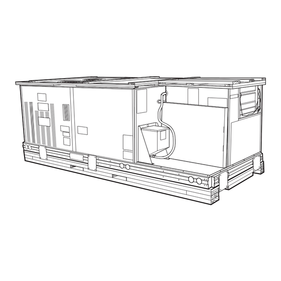
INSTALLATION Step 1 — Inspect Shipment — shipping company if shipment is incomplete or damaged. See Fig. 1 for a typical shipping packaging for a COBRA™ energy recovery unit. Step 2 — Provide Unit Support ROOF CURB — The COBRA energy recovery unit can use a full-perimeter roof curb or a standard roof curb for the rooftop section of the unit with a supplemental equipment support for the Fig. -
Page 3: Side View
DUCT OPENING SIZES Supply = 15 11/16" x 31 3/8" R1 = 15 5/16" x 29 1/16" R2 = 15 5/16" x 9" R1 = Return from building to HVAC R2 = Return from building to 62AQ SIDE VIEW Fig. 2B — COBRA™ Energy Recovery Unit Full-Perimeter Roof Curb — 48/50HJ008-014 with 62AQ200,300 If electric control power or gas service is to be routed through the basepan, a field-installed accessory thru-the- bottom connection must be used. - Page 4 CONNECTOR D ALT PKG. ACCY. DRAIN HOLE CRBTMPWR001A00 CRBTMPWR002A00 ″ 1′-9 1′-4″ CRBTMPWR003A00 [551] [406] [44.5] CRBTMPWR004A00 TO ENSURE AIRTIGHT CONNECTION. PLACE UNIT AS CLOSE TO THIS END AS POSSIBLE TO ENSURE AIRTIGHT CONNECTION. PLACE UNIT AS CLOSE TO THIS END AS POSSIBLE Fig.
- Page 5 CONNECTOR PKG. ACCY. CRBTMPWR001A00 CRBTMPWR002A00 ″ ″ 2′-8 1′-10 CRBTMPWR003A00 [827] [583] CRBTMPWR004A00 TO ENSURE AN AIRTIGHT CONNECTION, PLACE UNIT ON CURB AS CLOSE TO DUCT END AS POSSIBLE. TO ENSURE AN AIRTIGHT CONNECTION, PLACE UNIT ON CURB AS CLOSE TO DUCT END AS POSSIBLE.
-
Page 6: Positioning
C” Fig. 4 — Supplemental Energy Recovery Section Equipment Support Step 4 — Rig and Place Unit — and do not drop. Spreader bars are not required if top crating is left on unit. Rollers may be used to move unit across a roof. Remove the bottom wooden skids that are under the unit by removing the wooden plates that hold the bottom wooden frame to the unit. -
Page 11: Field Power Supply
48HJ004 w/62AQ060 48HJ004 w/62AQ100 48HJ005 w/62AQ060 48HJ005 w/62AQ100 48HJ006 w/62AQ060 48HJ006 w/62AQ100 48HJ007 w/62AQ060 48HJ007 w/62AQ100 50HJ004 w/62AQ060 50HJ004 w/62AQ100 50HJ005 w/62AQ060 50HJ005 w/62AQ100 50HJ006 w/62AQ060 50HJ006 w/62AQ100 50HJ007 w/62AQ060 50HJ007 w/62AQ100 Fig. 6A — Rigging Label — COBRA™ Energy Recovery Unit — Sizes 48/50HJ004-007 Step 5 —... -
Page 12: Disconnect
80 A for a COBRA Energy Recovery unit. For dis- connect amps greater than 80 A, a field-supplied disconnect is required. FIELD CONTROL WIRING — Install a Carrier-approved accessory thermidistat assembly according to installation instructions included with the accessory. Locate thermidistat as-... -
Page 13: Disconnect
NOTE: For wire runs up 50 ft, use no. 18 AWG (American Wire Gage) insulated wire (35 C minimum). For 50 to 75 ft, use no. 16 AWG insulated wire (35 C minimum). For over 75 ft, use no. 14 AWG insulated wire (35 C minimum). All wire larger than no. -
Page 14: Disconnect
Table 1B — Electrical Data (COBRA™ Energy Recovery 50HJ004-007 Units with 62AQ060) NOMINAL CONV UNIT V-PH-Hz TYPE OUTLET 208/230-1-60 208/230-3-60 HIGH STATIC 50HJ004 HIGH STATIC 460-3-60 HIGH STATIC HIGH STATIC 208/230-1-60 50HJ005 208/230-3-60 HIGH STATIC HIGH STATIC 460-3-60 HEAT POWER SUPPLY HEATER 62AQ CRHEATER... -
Page 15: Disconnect
Table 1B — Electrical Data (COBRA™ Energy Recovery 50HJ004-007 Units with 62AQ060) (cont) NOMINAL CONV UNIT V-PH-Hz TYPE OUTLET 50HJ005 460-3-60 HIGH STATIC (cont) HIGH STATIC 208/230-1-60 50HJ006 208/230-3-60 HIGH STATIC HIGH STATIC 460-3-60 LEGEND — Full Load Amps HACR — Heating, Air Conditioning and Refrigeration —... - Page 16 Table 1B — Electrical Data (COBRA™ Energy Recovery 50HJ004-007 Units with 62AQ060) (cont) NOMINAL CONV UNIT V-PH-Hz TYPE OUTLET HIGH STATIC 50HJ006 460-3-60 (cont) HIGH STATIC 208/230-3-60 HIGH STATIC HIGH STATIC 50HJ007 460-3-60 HIGH STATIC HIGH STATIC LEGEND — Full Load Amps HACR —...
-
Page 17: Disconnect
Table 1C — Electrical Data (COBRA™ Energy Recovery 48HJ004-007 Units with 62AQ100) NOMINAL UNIT V-PH-Hz TYPE 208/230-1-60 208/230-3-60 HIGH STATIC 48HJ004 HIGH STATIC 460-3-60 HIGH STATIC HIGH STATIC 208/230-1-60 208/230-3-60 HIGH STATIC 48HJ005 HIGH STATIC 460-3-60 HIGH STATIC HIGH STATIC 208/230-1-60 208/230-3-60 HIGH STATIC... -
Page 18: Disconnect
Table 1D — Electrical Data (COBRA™ Energy Recovery 50HJ004-007 Units with 62AQ100) NOMINAL CONV UNIT V-PH-Hz TYPE OUTLET 208/230-1-60 208/230-3-60 HIGH STATIC 50HJ004 HIGH STATIC 460-3-60 HIGH STATIC HIGH STATIC 208/230-1-60 50HJ005 208/230-3-60 HIGH STATIC HIGH STATIC 460-3-60 HEAT POWER SUPPLY HEATER 62AQ CRHEATER... -
Page 19: Disconnect
Table 1D — Electrical Data (COBRA™ Energy Recovery 50HJ004-007 Units with 62AQ100) (cont) NOMINAL CONV UNIT V-PH-Hz TYPE OUTLET 50HJ005 460-3-60 HIGH STATIC (cont) HIGH STATIC 208/230-1-60 50HJ006 208/230-3-60 HIGH STATIC HIGH STATIC 460-3-60 LEGEND — Full Load Amps HACR — Heating, Air Conditioning and Refrigeration —... -
Page 20: Disconnect
Table 1D — Electrical Data (COBRA™ Energy Recovery 50HJ004-007 Units with 62AQ100) (cont) NOMINAL CONV UNIT V-PH-Hz TYPE OUTLET 50HJ006 460-3-60 HIGH STATIC (cont) HIGH STATIC 208/230-3-60 HIGH STATIC HIGH STATIC 50HJ007 460-3-60 HIGH STATIC HIGH STATIC LEGEND — Full Load Amps HACR —... -
Page 21: Disconnect
Table 1E — Electrical Data (COBRA™ Energy Recovery 48HJ008-014 Units with 62AQ200) NOMINAL UNIT V-PH-HZ 208/230-3-60 HIGH STATIC HIGH STATIC 48HJ008 460-3-60 HIGH STATIC HIGH STATIC 208/230-3-60 HIGH STATIC HIGH STATIC 48HJ009 460-3-60 HIGH STATIC HIGH STATIC 208/230-3-60 HIGH STATIC HIGH STATIC 48HJ012 460-3-60... -
Page 22: Disconnect
Table 1F — Electrical Data (COBRA™ Energy Recovery 50HJ008-014 Units with 62AQ200) NOMINAL CONV UNIT V-PH-Hz TYPE OUTLET 208/230-3-60 HIGH STATIC HIGH STATIC 50HJ008 460-3-60 HIGH STATIC HIGH STATIC 208/230-3-60 HIGH STATIC HIGH STATIC 50HJ009 460-3-60 HIGH STATIC HIGH STATIC HEAT POWER SUPPLY HEATER... -
Page 23: Disconnect
Table 1F — Electrical Data (COBRA™ Energy Recovery 50HJ008-014 Units with 62AQ200) (cont) NOMINAL CONV UNIT V-PH-Hz TYPE OUTLET 208/230-3-60 HIGH STATIC HIGH STATIC 50HJ012 460-3-60 HIGH STATIC HIGH STATIC 208/230-3-60 50HJ014 460-3-60 LEGEND — Full Load Amps HACR — Heating, Air Conditioning and Refrigeration —... -
Page 24: Disconnect
Table 1G — Electrical Data (COBRA™ Energy Recovery 48HJ008-014 Units with 62AQ300) NOMINAL UNIT V-PH-Hz 208/230-3-60 HIGH STATIC HIGH STATIC 48HJ008 460-3-60 HIGH STATIC HIGH STATIC 208/230-3-60 HIGH STATIC HIGH STATIC 48HJ009 460-3-60 HIGH STATIC HIGH STATIC 208/230-3-60 HIGH STATIC HIGH STATIC 48HJ012 460-3-60... -
Page 25: Disconnect
Table 1H — Electrical Data (COBRA™ Energy Recovery 50HJ008-014 Units with 62AQ300) NOMINAL CONV UNIT V-PH-Hz TYPE OUTLET 208/230-3-60 HIGH STATIC HIGH STATIC 50HJ008 460-3-60 HIGH STATIC HIGH STATIC 208/230-3-60 HIGH STATIC HIGH STATIC 50HJ009 460-3-60 HIGH STATIC HIGH STATIC HEAT POWER SUPPLY HEATER... -
Page 26: Disconnect
Table 1H — Electrical Data (COBRA™ Energy Recovery 50HJ008-014 Units with 62AQ300) (cont) NOMINAL CONV UNIT V-PH-Hz TYPE OUTLET 208/230-3-60 HIGH STATIC HIGH STATIC 50HJ012 460-3-60 HIGH STATIC HIGH STATIC 50HJ014 208/230-3-60 LEGEND — Full Load Amps HACR — Heating, Air Conditioning and Refrigeration —... - Page 27 208/230-1-60 575-3-60 (SIZE 007 ONLY) 208/230-3-60 AND 460-3-60 (SIZES 008-014) LEGEND — Contactor COMP — Compressor — Indoor-Fan Contactor — National Electrical Code — Terminal Block Fig. 7 — Power Wiring Connections 208/230-3-60 460-3-60 (SIZE 007 ONLY) 208/230-3-60 575-3-60, 460-3-60 (SIZES 004-006) 575-3-60 (SIZES 008-014)
-
Page 28: Supply-Air Hood
FOR MOISTUREMI$ER UNITS ONLY LIGHT COMMERCIAL THERMIDISTAT ACCESSORY 62AQ CONNECTION BOARD Fig. 8 — Light Commercial Thermidistat Accessory Low-Voltage Connections DDC CONTROL CONNECTION BOARD 24 VAC RMTOCC CMPSAFE NOT USED Fig. 9 — Low Voltage Connections (Units with PremierLink™ Controls) RACEWAY LOW VOLTAGE INTEGRATED GAS UNIT... -
Page 29: Installation
Step 11 — Set the Outdoor Cooling and Heat- ing Thermostats IMPORTANT: The energy recovery section unit is shipped with an outdoor thermostat set at 55 F which locks out mechanical cooling on the RTU (rooftop unit) and the energy recovery section compressor. If this feature is not desirable, the rooftop unit’s compressor can be allowed to run by relocating both gray wires to the same side of the Low Temperature Lockout Thermostat (LTLO) leaving the... -
Page 30: Light Commercial Thermidistat
LIGHT COMMERCIAL THERMIDISTAT ACCESSORY General — A Light Commercial Thermidistat Accessory (part number TSTATCCPLH01-B) or PremierLink™ control- ler with humidistat is required for each unit for field installation to control the energy recovery section. See Fig. 13. The Light Commercial Thermidistat is a 7-day programma- ble, wall-mounted, low-voltage control which combines tem- perature and humidity control in a single unit. -
Page 31: Step 3 - Install Light Commercial Thermidistat
Step 3 — Install Light Commercial Thermidistat Before installing Light Commercial Thermidistat, turn off all power to Weathermaster® COBRA units. There may be more than one power disconnect. Electrical shock can cause personal injury or death. Install lockout tags on disconnects. - Page 32 COPY PREVIOUS PROGRAM MODE HUMIDITY CHANGE DAY RESET FILTER SET TIME/TEMP HOLIDAY HOLD Fig. 15 — Light Commercial Thermidistat Keypad Mode HOLD HOLIDAY DEHUM HEAT COOL COOL AUTO HEAT CLEAN FILTER ON** AUTO Fig. 16 — Light Commercial Thermidistat LCD on Power Up Option 2 —...
-
Page 33: Step 5 - Conduct Light Commercial Thermidistat Start-Up And Checkout
2 is selected, 72 F actual will read 74 F. If set point is 72 F, the room will control to an actual temperature of 70 F which will be displayed and acted upon as if it were 72 F. The effect is that a positive number selection will make the room temperature lower and vice versa. -
Page 34: Step 6 - Make Final Settings
Step 6 — Make Final Settings — DIP switch no. 4 back to OFF position to exit Installer Test mode. Assuming the system is to be left in operation after installation is complete, use MODE button to select between HEAT, COOL, or AUTO to provide desired operation of heat- ing, cooling, or both. -
Page 35: Pre-Start-Up
PRE-START-UP Failure to observe the following warnings could result in serious personal injury. 1. Follow recognized safety practices and wear protec- tive goggles and gloves when checking or servicing refrigerant system. 2. Do not operate compressor or provide any electric power to unit unless compressor terminal cover is in place and secured. - Page 36 ROOFTOP UNIT ENERGY RECOVERY SECTION OUTSIDE AIR MIXED AIR EXHAUST AIR ROOF LINE ROOM AIR SUPPLY AIR Fig. 17 — Unit Operation Flow Diagram Fig. 18 — Fuse Box (48HJ012, 014 — 208/230-3-60 Units Only)
- Page 37 Table 2 — Light Commercial Thermidistat (LCT) Operating Sequence and System Response COOLING Indoor Temperature Above 2nd Stage Set Point Humidity Low & OAT Low Humidity Low & OAT High Humidity High & OAT Low Humidity High & OAT High Indoor Temperature Between 1st and 2nd Stage Set Points Humidity Low &...
-
Page 38: Troubleshooting
Use Tables 3 and 4, and Fig. 19 and 20 when troubleshooting this unit. NOTES: 1. If any of the original wire furnished must be replaced, it must be replaced with Type 90° C wire or its equivalent. 2. Three phase motors are protected under primary single phasing conditions. - Page 39 Fig. 19 — Typical Wiring Schematic (Standard Controls) (cont)
- Page 40 Space Temp./ Set Point Adjustment Indoor Air Quality Sensor Outdoor Air Quality Sensor Power Exhaust/Energy Recycler ACCUSENSOR EconomiSer2 4 - 20mA LEGEND COMMS — Communications — Outdoor Air Temperature Sensor — Power — Supply Air Temperature Sensor Fig. 20 — Typical Wiring Schematic (with PremierLink™ Controls) TB - 2 TB - 3 RMTOCC...
- Page 41 Table 3 — Heating and Cooling Troubleshooting PROBLEM Compressor and outdoor fan Power failure. will not start. Fuse blown or circuit breaker tripped. Defective thermostat, contactor, transformer, con- trol relay, or capacitor. Insufficient line voltage. Incorrect or faulty wiring. Light Commercial Thermidistat program in UC1 or UC2 mode.
-
Page 42: Manufacturer Reserves The Right To Discontinue, Or Change At Any Time, Specifications Or Designs Without Notice And Without Incurring Obligations
Copyright 2002 Carrier Corporation Manufacturer reserves the right to discontinue, or change at any time, specifications or designs without notice and without incurring obligations. Book 1 PC 111 Catalog No. 534-80122 Printed in U.S.A. Form 48/50HJ,62AQ-2SIS Pg 42 9-02 Replaces: 48/50HJ,62AQ-1SIS... -
Page 43: Preliminary Information
ROOFTOP UNIT (RTU) AND ENERGY RECOVERY SECTION (62AQ) START-UP CHECKLIST I. PRELIMINARY INFORMATION COBRA™ ENERGY RECOVERY UNIT MODEL NO.: BASE UNIT MODEL NO.: DATE: II. PRE-START-UP (insert checkmark in box as each item is completed) VERIFY THAT CONDENSATE CONNECTION IS INSTALLED PER INSTALLATION INSTRUCTIONS CHECK ALL ELECTRICAL CONNECTIONS AND TERMINALS FOR TIGHTNESS CHECK THAT SUPPLY AND EXHAUST HOODS ARE INSTALLED AND AIR FILTER(S) ARE CLEAN AND IN PLACE... -
Page 44: Manufacturer Reserves The Right To Discontinue, Or Change At Any Time, Specifications Or Designs Without Notice And Without Incurring Obligations
OCCUPIED SETTINGS: ROOM TEMP ROOM RH TIMES: TIMES: Copyright 2002 Carrier Corporation Manufacturer reserves the right to discontinue, or change at any time, specifications or designs without notice and without incurring obligations. Book 1 PC 111 Catalog No. 534-80122 1a 1b 6a 6b...
Need help?
Do you have a question about the COBRA 48/50HJ004-014 and is the answer not in the manual?
Questions and answers