
Related Manuals for THORLABS HPLS343


Summary of Contents for THORLABS HPLS343
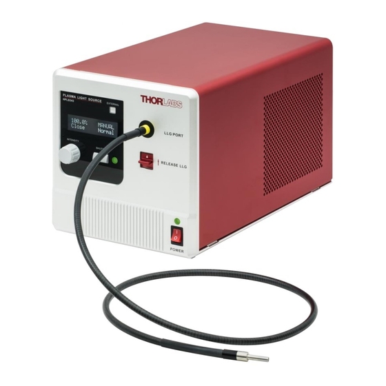
- Page 1 HPLS343 & HPLS345 High-Power Plasma Light Sources with Liquid Light Guides User Guide...
-
Page 2: Table Of Contents
Plasma Light Sources with Liquid Light Guide Table of Contents Warning Symbol Definitions ....................1 Chapter 1 Safety ............................ 2 Chapter 2 Description ........................... 3 Chapter 3 3.1. Overview .......................... 3 3.2. Light Emitting Plasma ..................... 3 3.3. Liquid Light Guide ......................4 3.4. - Page 3 8.3.12. LON=n; LON? – Bulb Module ON/OFF ................27 8.3.13. ERR? – Error message ....................... 28 8.3.14. WAR? – Warning Message ....................28 Specifications ........................29 Chapter 9 Mechanical Drawing ......................30 Chapter 10 Certifications and Compliances ..................31 Chapter 11 Chapter 12 Regulatory ...........................33 Chapter 13 Thorlabs Worldwide Contacts ..................34...
-
Page 4: Chapter 1 Warning Symbol Definitions
Plasma Light Sources with Liquid Light Guide Chapter 1: Warning Symbol Definitions Warning Symbol Definitions Chapter 1 Below is a list of warning symbols you may encounter in this manual or on your device. Symbol Description Direct Current Alternating Current Both Direct and Alternating Current Earth Ground Terminal Protective Conductor Terminal... -
Page 5: Chapter 2 Safety
Plasma Light Sources with Liquid Light Guide Chapter 2: Safety Safety Chapter 2 The lamp comes with a switching power supply compatible with voltages from 100 to 240 VAC. There is no need to change the fuse when selecting your regional voltage. If the user needs to change the fuse located below the AC plug on the back of the unit, see section 6.1. -
Page 6: Chapter 3 Description
Description Chapter 3 3.1. Overview Thorlabs’ HPLS300 series plasma light sources combine the best features of solid-state electronics and full spectrum plasma emitters. The Luxim ® Light Emitting Plasma (LEP)™ bulb module uses a ceramic resonant cavity to efficiently couple power from a solid-state power amplifier into a high-intensity discharge vessel. This technique results in the long life of the bulb module (6000 hours typical operating time before the optical power output at given driving current drops to 50% of the initial intensity) and produces a complete color spectrum. -
Page 7: Liquid Light Guide
Typical Output Spectrum of the HPLS343/345 The HPLS343 and HPLS345 light sources provide a full color spectrum from 350 nm to 800 nm. Figure 2 shows a typical output spectrum of an HPLS343 and HPLS345 light source, measured at the output tip of the liquid light guide. -
Page 8: Chapter 4 Setup
One 3 mm Hex Key One 2 mm Hex Key 4.2. Operation Elements Figure 3 Front and Back Panel of the HPLS343/HPLS345 Light Sources F1. External Control Button with LED B1. BNC Port for External Shutter Control: 5 V CMOS ... -
Page 9: Initial Setup
The light source also has four slots, located at the four bottom corners. As shown in Figure 4, by using Thorlabs table clamp CL6 or CL8, together with one of Thorlabs' baseplates, one can securely mount the plasma light source onto the surface of an optical table or breadboard with 1/4"-20 or M6 threaded mounting holes. - Page 10 We highly recommend using the LLGs featuring the yellow marking ring with these light sources, though all of Thorlabs’ standard liquid light guides are compatible, taking core diameter into consideration. When using an LLG that does not have the marking ring, there is the risk that the light guide may not be inserted to the proper depth during installation.
-
Page 11: Microscope Collimation Adapters
With these collimation adapters, users can easily couple the white light output from an HPLS343 or HPLS345 light source to either the epi-illumination or the trans-illumination port of the compatible microscopes above. The broadband spectrum, high brightness, and high color rendering index of these light sources makes them ideal for both fluorescence and bright field microscopy. -
Page 12: Chapter 5 Operation
Plasma Light Sources with Liquid Light Guide Chapter 5: Operation Operation Chapter 5 SHOCK WARNING High voltage inside. To avoid electrical shock, before powering unit, make sure that the protective conductor of the 3-conductor power cord is correctly connected to the protective earth contact of the socket outlet. -
Page 13: Lcd Screen
During tuning, the intensity percentage display on the LCD screen will change accordingly. The HPLS343 and HPLS345 light sources feature an intensity tuning function with a range of 0.1% to 100%, with a setting resolution of 0.1%. The tuning knob is functional regardless the state of the shutter (closed or open). -
Page 14: External Shutter Operation
Plasma Light Sources with Liquid Light Guide Chapter 5: Operation 5.5.1. External Shutter Operation The shutter can be controlled via the “SHUTTER CONTROL” port on the back panel. The female BNC port accepts a 5 V CMOS signal. A low logic state will open the shutter and a high logic state will close the shutter. Port Name Connector Signal Type... -
Page 15: Signal Train
Plasma Light Sources with Liquid Light Guide Chapter 5: Operation 5.5.4. Signal Train Figure 10 gives an example of the signal train in the HPLS300 series light source, when set to external control mode. When the “ANALOG IN” signal changes, the light source actually does nothing until a “TRIGGER IN” pulse arrives. Then at the falling edge of the trigger, the light source will start to tune its light intensity according to the “ANALOG IN”... -
Page 16: Operation Modes
Plasma Light Sources with Liquid Light Guide Chapter 5: Operation 5.6. Operation Modes The HPLS300 series features three different operation modes: open loop, closed loop, and Eco mode. The light source is set to open loop mode before shipping. The operation mode can only be changed via the software GUI or the command lines as described in Chapter 8. -
Page 17: Stability And Noise
Plasma Light Sources with Liquid Light Guide Chapter 5: Operation 5.7. Stability and Noise Figure 13 and Figure 14 present detailed light intensity measurements performed for sources operating in open and closed loop modes for 48 hours. The closed loop mode data also applies to operation in Eco mode. Measurements taken before the LLG record only the variation of the intensity emitted by the bulb. -
Page 18: Warning And Errors
Warning and Errors The HPLS343 and HPLS345 light sources have two different types of malfunction states: warning and error. Warning refers to a state of minor malfunction. The light source is still operational under a state of warning, but it may not perform as expected or according to specifications. -
Page 19: Chapter 6 Maintenance
50% of the initial value. It is not an absolute measurement of bulb lifetime. The actual lifetime of each bulb module may vary from unit to unit. Thorlabs provides a one year warranty on the bulb modules. Page 16... - Page 20 Plasma Light Sources with Liquid Light Guide Chapter 6: Maintenance To replace the bulb module, first remove the six cap screws on the back panel with the included 2 mm hex key. Then remove the red cover by sliding it backwards. Figure 16 Remove the six screws on the back Figure 17 Slide the red cover backwards to panel.
- Page 21 Plasma Light Sources with Liquid Light Guide Chapter 6: Maintenance Use the included 3 mm hex key to remove the two cap crews close to the back panel. Figure 19 Remove Two Cap Screws on the Back There are two cables connected to the bulb module from beneath, as shown in Figure 20. Smaller Connector Lower Connector Figure 20 Wire Connectors under the Bulb Module...
- Page 22 Plasma Light Sources with Liquid Light Guide Chapter 6: Maintenance Disconnect the smaller cable by pressing the clip and pulling the connector carefully downward. Press the Clip Down While Pulling the Connector Out Figure 21 Remove the Smaller Cable First Hold the bulb module firmly and slide it backwards until it completely disconnects from the lens holder in front of it.
-
Page 23: Firmware Update
Firmware Update The firmware update tool for HPLS300 series light sources and the most up-to-date firmware is available at www.thorlabs.com. Before updating the firmware, download and install the firmware update tool and download the latest firmware zip file. Connect the light source to a PC via USB, and switch on the device while holding down the “SHUTTER” button on the front panel. -
Page 24: Chapter 7 Software Gui
7 and 10 as detailed on the Thorlabs website. After installing the software package and connecting the host PC to the light source via the USB port on the back panel, the PC can control the light source using either a command-line interface, discussed in Chapter 8, or through a GUI. -
Page 25: Chapter 8 Command Line Operation
Plasma Light Sources with Liquid Light Guide Chapter 8: Command Line Operation Command Line Operation Chapter 8 8.1. Command-Line Interface Overview The HPLS300 series light sources can be controlled by a command-line language through the USB port. Users can either use a terminal emulator or write their own program to control the unit. The command language is described below. -
Page 26: Command Summary
Plasma Light Sources with Liquid Light Guide Chapter 8: Command Line Operation 8.2. Command Summary The table below lists all the available commands for the operation of HPLS343/345. Command Syntax Description List the available commands Get Commands Returns the model number, hardware and firmware... -
Page 27: Description Of Commands
8.3.2. *idn? or *IDN? – Device Information Queries the device part number, hardware and firmware versions. Return: THORLABS HPLS300 SNxxxxxxxx HWx.x FWx.x Where SN is the series number; HW is the hardware version; and FW is the firmware version. 8.3.3. SN? – Device Serial Number Queries the device serial number. -
Page 28: St? - Device Status
Plasma Light Sources with Liquid Light Guide Chapter 8: Command Line Operation 8.3.5. ST? – Device Status Queries the device status Return: ST=n The value of n can be one of the following status: n=1: Intializing; n=2: Normal; n=3: Error; n=4: Warning 8.3.6. -
Page 29: Lat? - Bulb Module Temperature
Plasma Light Sources with Liquid Light Guide Chapter 8: Command Line Operation 8.3.8. LAT? – Bulb Module Temperature Queries current lamp temperature Return: LAT=n Where n is the value of lamp temperature in °C. 8.3.9. LLG? – Light Guide Temperature Queries current light guide temperature. -
Page 30: Lad=N; Lad? - Operation Mode
Plasma Light Sources with Liquid Light Guide Chapter 8: Command Line Operation 8.3.11. LAD=n; LAD? – Operation Mode The LAD command is used to set or query the device operation mode. LAD=n Sets the lamp control mode. The value of n can be one of the following: n=1: Closed loop n=2: Open loop n=3: Eco... -
Page 31: Err? - Error Message
Plasma Light Sources with Liquid Light Guide Chapter 8: Command Line Operation 8.3.13. ERR? – Error message The ERR? command queries current device error message. Return: ERR=n Where n is an 8-bit number which reports the detailed error message. When converted into binary form, n has the following Boolean structure: n = 0000 0000 0000 0001 = bulb module temperature too high... -
Page 32: Chapter 9 Specifications
Plasma Light Sources with Liquid Light Guide Chapter 9: Specifications Specifications Chapter 9 Specification HPLS343 HPLS345 350 - 800 nm Wavelength Range 6000 K Color Temperature Color Rendering Index (CRI) 3 mm 5 mm LLG Core Diameter 0.59 LLG Numerical Aperture (NA) 7.0 W... -
Page 33: Chapter 10 Mechanical Drawing
Plasma Light Sources with Liquid Light Guide Chapter 10: Mechanical Drawing Chapter 10 Mechanical Drawing Figure 24 Mechanical Drawing Page 30 CTN009142-D02... -
Page 34: Chapter 11 Certifications And Compliances
Plasma Light Sources with Liquid Light Guide Chapter 11: Certifications and Compliances Chapter 11 Certifications and Compliances Page 31 Rev F, June 12, 2019... - Page 35 Plasma Light Sources with Liquid Light Guide Chapter 11: Certifications and Compliances Page 32 CTN009142-D02...
-
Page 36: Chapter 12 Regulatory
Waste Treatment is Your Own Responsibility If you do not return an “end of life” unit to Thorlabs, you must hand it to a company specialized in waste recovery. Do not dispose of the unit in a litter bin or at a public waste disposal site. -
Page 37: Chapter 13 Thorlabs Worldwide Contacts
Plasma Light Sources with Liquid Light Guide Chapter 13: Thorlabs Worldwide Contacts Chapter 13 Thorlabs Worldwide Contacts For technical support or sales inquiries, please visit us at www.thorlabs.com/contact for our most up-to- date contact information. USA, Canada, and South America UK and Ireland Thorlabs, Inc. - Page 38 www.thorlabs.com...
Need help?
Do you have a question about the HPLS343 and is the answer not in the manual?
Questions and answers