Table of Contents
Advertisement
Quick Links
Advertisement
Table of Contents

Related Manuals for THORLABS SLS203L


Summary of Contents for THORLABS SLS203L
- Page 1 SLS203L(/M) Stabilized Globar IR Light Source User Guide...
-
Page 2: Table Of Contents
4.5. Front Lens Tube ......................9 4.6. Application Ideas ......................10 4.7. Globar Module Replacement ..................10 Chapter 5 Specifications ........................14 Chapter 6 Mechanical Drawing ......................15 Chapter 7 Certifications and Compliances ..................16 Chapter 8 Regulatory ...........................17 Chapter 9 Thorlabs Worldwide Contacts ..................18 ... -
Page 3: Chapter 1 Warning Symbol Definitions
Stabilized Benchtop Globar Light Source Chapter 1: Warning Symbol Definitions Chapter 1 Warning Symbol Definitions Below is a list of warning symbols you may encounter in this manual or on your device. Symbol Description Direct Current Alternating Current Both Direct and Alternating Current Earth Ground Terminal Protective Conductor Terminal Frame or Chassis Terminal... -
Page 4: Chapter 2 Safety
Stabilized Benchtop Globar Light Source Chapter 2: Safety Chapter 2 Safety The lamp comes with a switching power supply compatible with voltages from 100 to 240 VAC. There is no need to change the fuse. WARNING Do not operate this device in explosive environments. WARNING Do not operate this device in wet or damp conditions. -
Page 5: Chapter 3 Product Overview
Stabilized Benchtop Globar Light Source Chapter 3: Product Overview Chapter 3 Product Overview 3.1. Planck's Law and Blackbody Radiation A black body is an object that absorbs all incident electromagnetic radiation (e.g. light), no light passes through or is reflected. However, despite the name, a black body will also emit electromagnetic radiation. The radiation of a black body in thermal equilibrium is described by Planck’s Law: Where is the radiated power per unit area of emitting surface per unit wavelength at temperature... -
Page 6: Optical Configuration
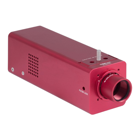
Optical Configuration The SLS203L is a silicon carbide Globar light source. The Globar is placed inside the housing, it is placed at one focus of an ellipsoid reflector. The output from the ellipsoid reflector is then collimated again with a CaF collimating lens. -
Page 7: Beam Profile And Divergence
Beam Profile and Divergence Figure 5 gives an illustration of what the beam profile of SLS203L looks like at near and far field respectively. The near field is defined as right at the output port with the front lens tube removed. The far field is defined as 1m away from the output port of the light source. -
Page 8: Output Stabilization
3.5. Output Stabilization Unlike traditional light sources, the SLS203L will not suffer from a gradual decrease nor short term fluctuation in brightness during its lifetime. SLS203L Silicon Carbide Light Source is equipped with an internal feedback loop and therefore can ensure a constant intensity, low noise and long life span. -
Page 9: Chapter 4 Operation
Setting Up on a Working Surface The SLS203L light source has four non-adjustable plastic feet at the bottom. It can be placed directly onto a flat working surfaces, as shown in Figure 9 (a). It also has two 1/4"-20 (M6) threaded mounting hole on the bottom, which are compatible with Thorlabs standard optical posts and post holders, thus can be mounted on a breadboard or optical as shown in Figure 9 (b). -
Page 10: Switching On The Light Source
4.3. Switching on the Light Source After setting up the light source on a working surface, follow the steps shown in Figure 10 to switch on SLS203L. Figure 10 Switching on the SLS203L Connect the power adaptor to the 3-pin socket on the back panel of the light source;... -
Page 11: Filter Holder
Front Lens Tube SLS203L also features a lens tube at the output of the device. This lens tube has SM1 internal thread and includes one SM1 retaining ring. The lens tube does not come with any optics by default, but it can mount Ø25 mm or Ø1"... -
Page 12: Application Ideas
Thorlabs standard 1 inch lens tubes and optical mounts. Fig 13 shows an application idea of how to implement the SLS203L to 30 mm cage systems and 1 inch lens tubes. Figure 13 SLS203L with 30 mm Cage System and 1" Lens Tube 4.7. - Page 13 Stabilized Benchtop Globar Light Source Chapter 4: Operation Thorlabs offer re-aligned Globar replacement modules for SLS203L IR light source. The replacement module are available on www.thorlabs.com under the PN of SLS253. To replace the Globar module. Place the light source up-side down to reveal the underside of the unit. Using the included 5/64"...
- Page 14 Stabilized Benchtop Globar Light Source Chapter 4: Operation Then using the included 1.5 mm hex key included with the replacement module, remove the cap screw that locks the Globar module. Figure 16 Loosen the Globar Locking Screw Unplug the white plug that is connected to the Globar module. (It is located on the far side of the circuit board if the output aperture of the lamp is facing to the right.) Unplug Figure 17 Unplug the Globar Module Connector...
- Page 15 Stabilized Benchtop Globar Light Source Chapter 4: Operation PD Signal Wire Figure 18 Pull Out the Globar Module Two aluminum dowel pins, located on either side of the Globar module, may slip out of their holes while the module is being removed. Be careful not to misplace them as they are needed for the new module installation. Figure 19 Dowel Pins on the Globar Module To install the new Globar module, place the two dowel pins in their corresponding holes in the new Globar module.
-
Page 16: Chapter 5 Specifications
Stabilized Benchtop Globar Light Source Chapter 5: Specifications Chapter 5 Specifications Specification Value Wavelength Range 500 – 9000 nm Color Temperature 1500 K Peak Wavelength 2400 nm Color Temperature Stability ±15 K Globar Power 24 W Output Optical power >1.5 W Globar Lifespan (Average) 10 000 hrs 0.03%... -
Page 17: Chapter 6 Mechanical Drawing
Stabilized Benchtop Globar Light Source Chapter 6: Mechanical Drawing Chapter 6 Mechanical Drawing Page 15 Rev C, May 8, 2017... -
Page 18: Chapter 7 Certifications And Compliances
Stabilized Benchtop Globar Light Source Chapter 7: Certifications and Compliances Chapter 7 Certifications and Compliances This device complies with Part 15 of the FCC Rules. Operation is subject to the following two conditions: (1) this device may not cause harmful interference, and (2) this device must accept any interference received, including interference that may cause undesired operation. -
Page 19: Chapter 8 Regulatory
Waste Treatment is Your Own Responsibility If you do not return an “end of life” unit to Thorlabs, you must hand it to a company specialized in waste recovery. Do not dispose of the unit in a litter bin or at a public waste disposal site. -
Page 20: Chapter 9 Thorlabs Worldwide Contacts
Fax: +46-31-703-40-45 www.thorlabs.de www.thorlabs.com Email: europe@thorlabs.com Email: scandinavia@thorlabs.com France Brazil Thorlabs SAS Thorlabs Vendas de Fotônicos Ltda. 109, rue des Côtes Rua Riachuelo, 171 78600 Maisons-Laffitte São Carlos, SP 13560-110 France Brazil Tel: +33 (0) 970 444 844 Tel: +55-16-3413 7062... - Page 21 www.thorlabs.com...
Need help?
Do you have a question about the SLS203L and is the answer not in the manual?
Questions and answers