Graco Husky 3300e Operation
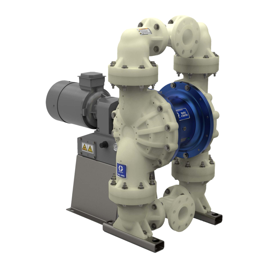
Electric-operated diaphragm pump
Hide thumbs
Also See for Husky 3300e:
- Operation (38 pages) ,
- Manual (38 pages) ,
- Repair parts (38 pages)
Advertisement
Quick Links
Operation
Husky™ 3300e
3300e
Husky™
Husky™
3300e
Electric
Electric
Electric - - - Operated
Operated Diaphragm
Operated
3 3 3 - - - Inch
Inch pumps
Inch
pumps with
pumps
with electric
with
electric drive
electric
atmospheres or or or hazardous
hazardous (classified)
atmospheres
atmospheres
hazardous
Important
Important Safety
Important
Safety Instructions
Safety
Read all warnings and instructions in this manual and in your
Repair/Parts manual. Save
Maximum Working Pressure: 80 psi
(0.55 MPa, 5.5 bar)
All manuals and user guides at all-guides.com
Diaphragm
Diaphragm Pump
drive for
drive
for fluid
for
fluid
fluid transfer
transfer applications.
transfer
(classified) locations
locations unless
(classified)
locations
Instructions
Instructions
Save all all all instructions.
Save
instructions.
instructions.
PROVEN QUALITY. LEADING TECHNOLOGY.
Pump
Pump
applications. Not
applications.
Not approved
Not
approved for
approved
unless otherwise
otherwise stated.
stated. For
unless
otherwise
stated.
3A7036E
3A7036E
3A7036E
for use
for
use in in in explosive
use
explosive
explosive
For professional
professional use
use only.
only.
For
professional
use
only.
EN
EN
EN
Advertisement

Related Manuals for Graco Husky 3300e


Summary of Contents for Graco Husky 3300e
- Page 1 All manuals and user guides at all-guides.com Operation Husky™ 3300e 3300e Husky™ Husky™ 3300e 3A7036E 3A7036E 3A7036E Electric Electric Electric - - - Operated Operated Diaphragm Operated Diaphragm Diaphragm Pump Pump Pump 3 3 3 - - - Inch Inch pumps Inch pumps pumps with...
- Page 2 Use ............18 Graco Standard...
- Page 3 All manuals and user guides at all-guides.com Warnings Warnings Warnings Warnings The following warnings are for the setup, use, grounding, maintenance, and repair of this equipment. The exclamation point symbol alerts you to a general warning and the hazard symbols refer to procedure-specific risks.
- Page 4 All manuals and user guides at all-guides.com Warnings WARNING PRESSURIZED EQUIPMENT EQUIPMENT HAZARD HAZARD PRESSURIZED PRESSURIZED EQUIPMENT HAZARD Fluid from the equipment, leaks, or ruptured components can splash in the eyes or on skin and cause serious injury. • Follow the Pressure Pressure Relief Pressure Relief Procedure...
- Page 5 All manuals and user guides at all-guides.com Warnings WARNING THERMAL EXPANSION EXPANSION HAZARD HAZARD THERMAL THERMAL EXPANSION HAZARD Fluids subjected to heat in confined spaces, including hoses, can create a rapid rise in pressure due to the thermal expansion. Over-pressurization can result in equipment rupture and serious injury.
- Page 6 All manuals and user guides at all-guides.com Configuration Number Matrix Configuration Number Number Matrix Matrix Configuration Configuration Number Matrix Check Check Check the the identification identification plate identification plate (ID) plate (ID) (ID) for for the Configuration Configuration Configuration Number Number of of of your Number your pump.
- Page 7 All manuals and user guides at all-guides.com Configuration Number Matrix Fluid Covers Covers and Seat Material Material Ball Ball Ball Material Material Material Diaphragm Diaphragm Diaphragm Material Material Material Manifold/Seat Fluid Fluid Covers Seat Seat Material Manifold/Seat Manifold/Seat Manifolds Manifolds Manifolds O O O - - - Rings Rings...
- Page 8 Online Electric Electric Operated Operated Diaphragm Diaphragm Pump Pump Selector Selector Tool Tool at at at www.graco.com. . . Search for Selector. Use the Online Online Electric Operated Diaphragm Pump Selector Tool www.graco.com www.graco.com To Order...
- Page 9 Graco recommends taking all the above factors into account in system design. To maintain pump efficiency, supply only enough power to the pump to achieve the required flow. Graco distributors can supply site specific suggestions to improve pump performance and reduce operating costs.
- Page 10 All manuals and user guides at all-guides.com Installation Figure 1 Typical Installation for pumps without a compressor System Components Components Required Components Components Not Not Supplied Supplied System System Components Required Required Components Supplied Fluid inlet port Power cord to VFD Fluid outlet port Grounded, flexible air supply line Mounting feet...
- Page 11 All manuals and user guides at all-guides.com Installation Figure 2 Typical installation of a pump with compressor System Components Components Required Components Components Not Not Supplied Supplied System System Components Required Required Components Supplied Fluid inlet port Power cord to VFD Fluid outlet port Power cord to compressor Mounting feet...
- Page 12 Gearmotor Gearmotor Mounting Mounting pump without Gearmotor A A A pump pump without pump without without a a a Graco Graco gearbox Graco gearbox and gearbox and motor motor will motor will will require require a a a mounting...
- Page 13 Insert one end of a 12–gauge minimum ground wire behind the ground screw and tighten the screw securely. Connect the clamp end of the grounding wire to a true earth ground. A ground wire and clamp, Part 238909, is available from Graco. 3A7036E...
- Page 14 All manuals and user guides at all-guides.com Installation Air Line Line Line Fluid Supply Supply Line Line Fluid Fluid Supply Line 1. 1. 1. Connect Connect a a a grounded, Connect grounded, flexible grounded, flexible fluid flexible fluid hose fluid hose hose (K) (K) to to to...
- Page 15 Use a motor soft starter or a VFD in the electrical circuit for all installations (not supplied). VFDs can be purchased through Graco. See recommended VFD kits on page 36. Wire Wire Wire Connections Connections...
- Page 16 3. 3. 3. For For a a a Graco Graco Graco VFD, VFD, perform VFD, perform the perform the following: following: following: a. a. a. Wire Wire one...
- Page 17 Follow Follow Follow these these these instructions instructions to to to wire instructions wire wire Graco Graco Graco Compressor Compressor Compressor 2. 2. 2. Install Install wiring wiring system system with with proper proper connections connections (i.e.
- Page 18 All manuals and user guides at all-guides.com Operation Operation Operation Operation 3. 3. 3. Place Place the Place the suction suction tube suction tube tube (if (if (if used) used) used) in in in fluid fluid to to to be fluid pumped.
- Page 19 All manuals and user guides at all-guides.com Operation Pressure Relief Relief Procedure Procedure Pump Shutdown Shutdown Pressure Pressure Relief Procedure Pump Pump Shutdown Follow the Pressure Relief Procedure whenever you see this symbol. At the end of the work shift and before you check, adjust, clean, or repair the system, follow the Pressure Relief Procedure, page This equipment stays pressurized until pressure...
- Page 20 VFD Control Control Control Panel Panel Panel NOTE: NOTE: NOTE: This This This information information information is is is specific specific to to to Graco’s specific Graco’s Graco’s VFD. VFD. VFD. For For complete complete complete information information information about...
- Page 21 All manuals and user guides at all-guides.com Maintenance Maintenance Maintenance Maintenance Flushing Flushing and Flushing and Storage Storage Storage To avoid avoid injury injury from from fire, fire, explosion, explosion, or or or electric electric avoid injury from fire, explosion, electric shock, all all all electrical electrical wiring...
- Page 22 All manuals and user guides at all-guides.com Torque Instructions Torque Torque Torque Instructions Instructions Instructions 1. 1. 1. Start Start all all all fluid fluid cover cover screws screws a a a few few turns. turns. Then, Then, turn turn If fluid cover or manifold fasteners have been Start fluid...
- Page 23 All manuals and user guides at all-guides.com Torque Instructions Stainless Steel Steel Pumps Pumps Stainless Stainless Steel Pumps 1. Left/Right Fluid Covers 2. Manifolds Torque bolts 5-12 to 40-45 ft-lb (54-60 N•m) Torque bolts to 40-45 ft-lb (54-60 Torque bolts 1-4 to 110-120 in-lb N•m) (12–13 N•m) SIDE VIEW...
- Page 24 All manuals and user guides at all-guides.com Performance Charts Performance Charts Charts Performance Performance Charts Test Conditions: Conditions: The The pump pump was was tested tested in in in water water with with 3. 3. 3. Set Set the the VFD VFD frequency frequency corresponding corresponding to to to the...
- Page 25 All manuals and user guides at all-guides.com Performance Charts How to to to Calculate Calculate Your Your System’s System’s Net Net Positive Positive Suction Suction Head Head – – – Available Available Calculate Your System’s Positive Suction Head Available (NPSHa) (NPSHa) (NPSHa) For a given flow rate, there must be a minimum...
- Page 26 All manuals and user guides at all-guides.com Dimensions Dimensions Dimensions Dimensions Aluminum pump with compressor 3A7036E...
- Page 27 All manuals and user guides at all-guides.com Dimensions Aluminum pump without compressor 3A7036E...
- Page 28 All manuals and user guides at all-guides.com Dimensions Table Table Table 1 1 1 Dimensions Dimensions for Dimensions for Aluminum Aluminum Pumps Aluminum Pumps Pumps Gearbox and and Motor Motor Code Code – – – Dimensions Dimensions shown shown in in in inches inches (cm) (cm) Gearbox...
- Page 29 All manuals and user guides at all-guides.com Dimensions Polypropylene pump with compressor 3A7036E...
- Page 30 All manuals and user guides at all-guides.com Dimensions Polypropylene pump without compressor 3A7036E...
- Page 31 All manuals and user guides at all-guides.com Dimensions Table Table Table 2 2 2 Dimensions Dimensions for Dimensions for Polypropylene Polypropylene Pumps Polypropylene Pumps Pumps Gearbox and and Motor Motor Code Code – – – Dimensions Dimensions shown shown in in in inches inches (cm) (cm) Gearbox...
- Page 32 All manuals and user guides at all-guides.com Dimensions Stainless steel pump with compressor 3A7036E...
- Page 33 All manuals and user guides at all-guides.com Dimensions Stainless steel pump without compressor 3A7036E...
- Page 34 All manuals and user guides at all-guides.com Dimensions Table Table Table 3 3 3 Dimensions Dimensions Dimensions for for Stainless Stainless Steel Stainless Steel Steel Pumps Pumps Pumps Gearbox and and Motor Motor Code Code – – – Dimensions Dimensions shown shown in in in inches inches (cm) (cm)
- Page 35 All manuals and user guides at all-guides.com Technical Data Technical Technical Technical Data Data Data Husky Husky Husky Electric Electric Double Electric Double Double Diaphragm Diaphragm Pump Diaphragm Pump Pump Metric Metric Metric Maximum fluid fluid working working pressure pressure 80 psi 0.55 MPa, MPa, 5.5...
- Page 36 All manuals and user guides at all-guides.com Technical Data Speed 1800 rpm rpm (60 (60 Hz) Hz) or or or 1500 1500 rpm rpm (50 (50 Hz) Speed Speed 1800 1800 1500 Constant Torque Torque Constant Constant Torque Gear Gear Gear Ratio Ratio Ratio...
- Page 37 All manuals and user guides at all-guides.com California Proposition 65 Weights Weights Weights Pump Pump Pump Material Material Material Motor/Gearbox Motor/Gearbox Motor/Gearbox Flame- Standard Standard Standard ATEX ATEX ATEX AC Flame- Flame- No Gear- Gear- Gear- proof proof proof AC motor motor motor...
- Page 38 With the exception of any special, extended, or limited warranty published by Graco, Graco will, for a period of twelve months from the date of sale, repair or replace any part of the equipment determined by Graco to be defective.
Need help?
Do you have a question about the Husky 3300e and is the answer not in the manual?
Questions and answers