Table of Contents
Advertisement
Quick Links
Repair/Parts
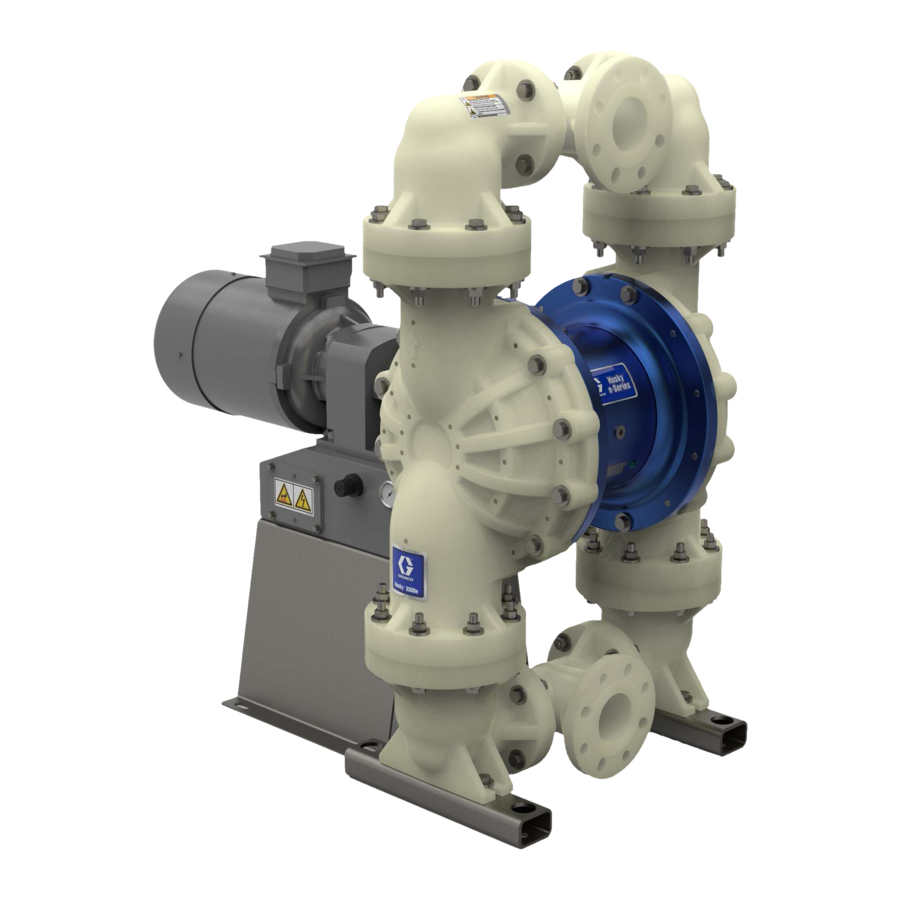
Husky™ 3300e
3300e
Husky™
Husky™
3300e
Electric
Electric - - - Operated
Electric
Operated Diaphragm
Operated
3 3 3 - - - Inch
Inch pumps
Inch
pumps
pumps with
with electric
with
electric drive
electric
Not approved
approved for
for use
use in in in explosive
Not
Not
approved
for
use
professional
professional use
professional
use only.
use
only.
only.
Important
Important Safety
Important
Safety Instructions
Safety
Read all warnings and instructions in this manual and in your Husky
3300e Operation manual. Save
Maximum working pressure: 80 psi
(0.55 MPa, 5.5 bar)
See page 7 for approvals.
All manuals and user guides at all-guides.com
Diaphragm Pump
Diaphragm
drive for
drive
for fluid
for
fluid
fluid transfer
transfer applications.
transfer
explosive atmospheres
atmospheres or or or hazardous
explosive
atmospheres
Instructions
Instructions
Save
Save these
these instructions.
these
instructions.
instructions.
PROVEN QUALITY. LEADING TECHNOLOGY.
Pump
Pump
applications.
applications.
hazardous locations
locations unless
hazardous
locations
3A7037G
3A7037G
3A7037G
unless otherwise
otherwise stated.
stated. For
unless
otherwise
stated.
EN
EN
EN
For
For
Advertisement
Table of Contents

Related Manuals for Graco Husky 3300e


Summary of Contents for Graco Husky 3300e
- Page 1 All manuals and user guides at all-guides.com Repair/Parts Husky™ 3300e 3300e Husky™ Husky™ 3300e 3A7037G 3A7037G 3A7037G Electric Electric Electric - - - Operated Operated Diaphragm Operated Diaphragm Diaphragm Pump Pump Pump 3 3 3 - - - Inch Inch pumps Inch pumps pumps with...
-
Page 2: Table Of Contents
All manuals and user guides at all-guides.com Contents Contents Contents Related Manuals Manuals ..............................2 2 2 Center Section Section Repair Repair . -
Page 3: Warnings
All manuals and user guides at all-guides.com Warnings Warnings Warnings Warnings The following warnings are for the setup, use, grounding, maintenance, and repair of this equipment. The exclamation point symbol alerts you to a general warning and the hazard symbols refer to procedure-specific risks. - Page 4 All manuals and user guides at all-guides.com Warnings WARNING PRESSURIZED EQUIPMENT EQUIPMENT HAZARD HAZARD PRESSURIZED PRESSURIZED EQUIPMENT HAZARD Fluid from the equipment, leaks, or ruptured components can splash in the eyes or on skin and cause serious injury. • Follow the Pressure Pressure Relief Pressure Relief Procedure...
- Page 5 All manuals and user guides at all-guides.com Warnings WARNING THERMAL EXPANSION EXPANSION HAZARD HAZARD THERMAL THERMAL EXPANSION HAZARD Fluids subjected to heat in confined spaces, including hoses, can create a rapid rise in pressure due to the thermal expansion. Over-pressurization can result in equipment rupture and serious injury.
-
Page 6: Configuration Configuration Number Configuration Number Matrix Number Matrix
All manuals and user guides at all-guides.com Configuration Number Matrix Configuration Number Number Matrix Matrix Configuration Configuration Number Matrix Check the identification plate (ID) for the Configuration Number of your pump. Use the following matrix to define the components of your pump. - Page 7 All manuals and user guides at all-guides.com Configuration Number Matrix Fluid Covers Covers and Seat Material Material Ball Ball Ball Material Material Material Diaphragm Diaphragm Diaphragm Material Material Material Manifold/Seat Fluid Fluid Covers Seat Seat Material Manifold/Seat Manifold/Seat Manifolds Manifolds Manifolds O O O - - - Rings Rings...
-
Page 8: Ordering Ordering Information Ordering Information
Online Diaphragm Diaphragm Pump Pump Selector Selector Tool Tool at at at www.graco.com. . . Search for Selector. Selector. Use the Online Online Diaphragm Pump Selector Tool www.graco.com www.graco.com Selector. To Order... -
Page 9: Troubleshooting
All manuals and user guides at all-guides.com Troubleshooting Troubleshooting Troubleshooting Troubleshooting • Follow the Pressure Relief Procedure, page before checking or servicing the equipment. • Check all possible problems and causes before disassembly. Problem Cause Solution Problem Problem Cause Cause Solution Solution Pump cycles but will not prime... - Page 10 All manuals and user guides at all-guides.com Troubleshooting Problem Cause Solution Problem Problem Cause Cause Solution Solution Air consumption is higher than A fitting is loose. Tighten. Inspect thread sealant. expected. Replace. Loose or damaged o-rings or shaft seal. Replace. Diaphragm (or backup) ruptured.
-
Page 11: Repair
All manuals and user guides at all-guides.com Repair Repair Repair Repair Pressure Relief Relief Procedure Procedure Pressure Pressure Relief Procedure Disassemble Disassemble the Disassemble the Check Check Valve Check Valve Valve 1. Follow the Pressure Relief Procedure, page Follow the Pressure Relief Procedure Remove power to the motor. - Page 12 All manuals and user guides at all-guides.com Repair Check valve valve assembly, assembly, aluminum aluminum model model shown shown Check Check valve assembly, aluminum model shown Apply medium-strength (blue) thread locker. Torque to the value specified for your pump. See Torque Instructions, page Arrow (A) must point toward outlet manifold Not used on some models.
-
Page 13: Replacement
All manuals and user guides at all-guides.com Repair Standard Diaphragm Diaphragm Replacement Replacement Standard Standard Diaphragm Replacement 6. Rotate the drive shaft to move the piston fully to the other side. See instructions in step 4. Repeat step 5. 7. To continue with disassembly, see Disassemble the Center Section, page Disassemble the the Standard... - Page 14 All manuals and user guides at all-guides.com Repair Reassemble the the Standard Standard Diaphragms Diaphragms Reassemble Reassemble Standard Diaphragms 4. Clean the female threads of the piston shaft with a wire brush dipped in solvent to remove any residual thread locker. Apply thread-locking NOTICE NOTICE NOTICE...
-
Page 15: Center Section Center Section Repair Section Repair
All manuals and user guides at all-guides.com Repair Center Section Section Repair Repair Center Center Section Repair 7. Use a 3/4-16 bolt to push out the drive shaft assembly (109). You can also use the bearing bolt (114), but remove the bearing (112) first. Be sure that the groove on the drive shaft remains aligned with the markings in the center section. - Page 16 All manuals and user guides at all-guides.com Repair Reassemble the the Center Center Section Section Reassemble Reassemble Center Section 1. Clean and dry the center housing (101), the 5. Install o-ring (108) to the center housing (101). center of the piston (105) and the drive shaft 6.
- Page 17 All manuals and user guides at all-guides.com Repair Apply medium-strength (blue) thread locker to threads. Torque to 15–25 ft-lb (20–34 N•m). Lips must face IN IN IN toward the center. Apply Loctite® Primer 7471 and Retaining Compound 641 to the bearing bore and outer race.
- Page 18 All manuals and user guides at all-guides.com Repair Disconnect the the Motor Motor and and Gearbox Gearbox Disconnect Disconnect Motor Gearbox NOTE: NOTE: NOTE: Normally, the motor remains connected to the 1. Use a 3/4 in. socket wrench to remove 4 screws gearbox.
-
Page 19: Leak Sensor Leak Sensor Repair Sensor Repair
All manuals and user guides at all-guides.com Repair Leak Sensor Sensor Repair Repair Leak Leak Sensor Repair The leak sensor can be replaced or re-positioned. e. If the continuity test result indicates that When properly positioned, the two arrows imprinted the leak sensor is not functioning properly, on two of the flat surfaces of the leak sensor hex proceed to step 3. -
Page 20: Compressor
All manuals and user guides at all-guides.com Repair Replace the the Compressor Compressor Replace Replace Compressor To avoid injury from fire, explosion, or electric shock, all electrical wiring must be done by a qualified electrician and comply with all local codes and regulations. - Page 21 All manuals and user guides at all-guides.com Torque Instructions Torque Torque Torque Instructions Instructions Instructions NOTE: Always completely torque fluid covers before If fluid cover or manifold fasteners have been NOTE: NOTE: loosened, it is important to torque them using the torquing manifolds.
- Page 22 All manuals and user guides at all-guides.com Torque Instructions Stainless Steel Steel Pumps Pumps Stainless Stainless Steel Pumps Torque bolts to 40-45 ft-lb (54.2–61.2 N•m) 1. Left/Right Fluid Covers 2. Inlet Manifold 3. Outlet Manifold BOTTOM VIEW TOP VIEW SIDE VIEW Plastic Pumps Pumps Plastic...
- Page 23 All manuals and user guides at all-guides.com Notes Notes Notes Notes 3A7037G...
-
Page 24: Parts
All manuals and user guides at all-guides.com Parts Parts Parts Parts Aluminum pump shown 3A7037G... - Page 25 All manuals and user guides at all-guides.com Parts Stainless steel pump shown 3A7037G...
- Page 26 All manuals and user guides at all-guides.com Parts Plastic pump shown 3A7037G...
- Page 27 All manuals and user guides at all-guides.com Parts Parts/Kits Quick Quick Reference Reference Parts/Kits Parts/Kits Quick Reference Use this table as a quick reference for parts/kits. Go to the pages indicated in the table for a full description of kit contents. Part/Kit Description Description Description...
- Page 28 All manuals and user guides at all-guides.com Parts Center Section Section Center Center Section Sample Configuration Number Pump Wetted Drive Center Motor Fluid Balls Diaphragms Manifold Gear Box Seats Model Section Covers Section and Motor O-Rings Material Material Manifolds 3300 A A A 3A7037G...
- Page 29 All manuals and user guides at all-guides.com Parts Part Description Part Description Part Part Description Description Part Part Description Description 25B415 HOUSING, center, assembly 1 17S683 COUPLER, gearbox; includes mounting hardware 17N208 O-RING, air cover GEARBOX 19Y144 AIR COVER 17Y810 IEC 132 for use with motor C included 115643...
- Page 30 All manuals and user guides at all-guides.com Parts Fluid Covers Covers and and Manifolds Manifolds Fluid Fluid Covers Manifolds Sample Configuration Number Pump Wetted Drive Center Motor Fluid Balls Diaphragms Manifold Gear Box Seats Model Section Covers Section and Motor O-Rings Material Material...
- Page 31 All manuals and user guides at all-guides.com Parts Sample Configuration Number Pump Wetted Drive Center Gear Box Motor Fluid Seats Balls Diaphragms Manifold Model Section Section and Motor Covers O-Rings Material Material Manifolds 3300 Polypropylene Polypropylene Polypropylene Manifold Manifold Kits Manifold Kits Kits...
- Page 32 All manuals and user guides at all-guides.com Parts Seats and and Check Check Balls Balls Seats Seats Check Balls Sample Configuration Number Pump Wetted Drive Center Motor Fluid Balls Diaphragms Manifold Gear Box Seats Model Section Covers Section and Motor O-Rings Material Material...
- Page 33 All manuals and user guides at all-guides.com Parts Diaphragms Diaphragms Diaphragms Sample Configuration Number Pump Wetted Drive Center Gear Box Motor Fluid Seats Balls Diaphragms Manifold Model Section Section and Motor Covers O-Rings Material Material Manifolds 3300 Bolt- - - Through Through Diaphragm Diaphragm Kits Kits...
- Page 34 All manuals and user guides at all-guides.com Parts Manifold Seals Seals Manifold Manifold Seals Sample Configuration Number Pump Wetted Drive Motor Fluid Balls Diaphragms Manifold Center Gear Box Seats Model Section Covers Section and Motor O-Rings Material Material Manifolds 3300 O O O - - - Ring Ring Ring Kits...
- Page 35 All manuals and user guides at all-guides.com Technical Data Technical Technical Technical Data Data Data Husky Husky Husky Electric Electric Double Electric Double Double Diaphragm Diaphragm Pump Diaphragm Pump Pump Metric Metric Metric 80 psi 0.55 MPa, 5.5 bar Maximum fluid working pressure Air pressure operating range 20 to 80 psi 0.14 to 0.55 MPa, 1.4...
- Page 36 All manuals and user guides at all-guides.com Technical Data Speed 1800 rpm (60 Hz) or 1500 rpm (50 Hz) Constant Torque Gear Ratio 11.88 Voltage 3–phase 230V / 3–Phase 460V Maximum Amperage Load 20.0 A (230V) / 10.0 A (460V) Leak Sensor Contact Ratings: State...
- Page 37 All manuals and user guides at all-guides.com California Proposition 65 Weights Weights Weights Pump Material Motor/Gearbox Standard ATEX AC Flame- No Gear- proof AC motor Fluid Center Section Section Aluminum Aluminum Polypropylene Aluminum Stainless Aluminum Steel Fluid Temperature Temperature Range Range Fluid Fluid...
- Page 38 With the exception of any special, extended, or limited warranty published by Graco, Graco will, for a period of twelve months from the date of sale, repair or replace any part of the equipment determined by Graco to be defective. This warranty applies only when the equipment is installed, operated and maintained in accordance with Graco’s written recommendations.
Need help?
Do you have a question about the Husky 3300e and is the answer not in the manual?
Questions and answers