Table of Contents
Advertisement
Instructions
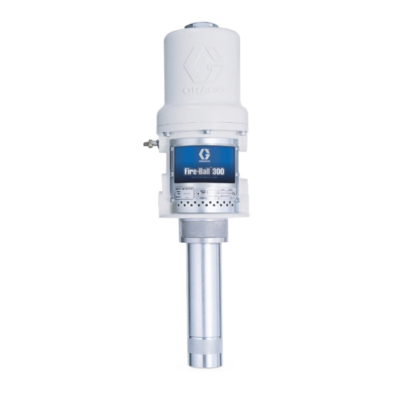
50:1 Fire-Ball
Pump
For pumping non-corrosive and non-abrasive greases and lubricants only.For
professional use only.
Model No. 239877, Series D
pail length
Model No. 239887, Series D
120 lb drum length
Model No. 239888, Series D
400 lb drum length
8400 psi (58 MPa, 580 bar) Maximum Working Pressure
140 psi (0.97 MPa, 9.7 bar) Maximum Air Input Pressure
Important Safety Instructions
Read all warnings and instructions in this
manual. Save these instructions.
This product is designed to be used only in pumping
non-corrosive and non-abrasive lubricants and
greases. Any other use can cause unsafe operating
conditions and result in component rupture, fire, or
explosion, which can cause serious injury including
fluid injection.
®
300
308883S
EN
Advertisement
Table of Contents

Related Manuals for Graco Fire-Ball 300 D Series


Summary of Contents for Graco Fire-Ball 300 D Series
- Page 1 Instructions ® 50:1 Fire-Ball Pump 308883S For pumping non-corrosive and non-abrasive greases and lubricants only.For professional use only. Model No. 239877, Series D pail length Model No. 239887, Series D 120 lb drum length Model No. 239888, Series D 400 lb drum length 8400 psi (58 MPa, 580 bar) Maximum Working Pressure 140 psi (0.97 MPa, 9.7 bar) Maximum Air Input Pressure Important Safety Instructions...
- Page 2 Warnings Warnings The following warnings are for the setup, use, grounding, maintenance, and repair of this equipment. The exclama- tion point symbol alerts you to a general warning and the hazard symbols refer to procedure-specific risks. When these symbols appear in the body of this manual or on warning labels, refer back to these Warnings. Product-specific hazard symbols and warnings not covered in this section may appear throughout the body of this manual where applicable.
-
Page 3: Installation
Installation Installation Grounding To maintain grounding continuity when flushing or relieving pressure: hold metal part of the spray gun/dispense valve firmly to the side of a grounded metal pail, then trigger the gun/valve. To ground the pump: remove the ground screw (Z) The equipment must be grounded to reduce the risk and insert through the eye of the ring terminal at end of of static sparking and electric shock. -
Page 4: Air And Fluid Line Accessories
Installation Mounting • The ground wire (B) reduces the risk of static sparking. NOTICE Do not hand the air accessories directly on the air inlet. The fittings are not strong enough to support the Mount the pump securely so that it cannot move accessories and may cause one or more to break. -
Page 5: Operation
Operation Operation Pressure Relief Procedure NOTICE Follow the Pressure Relief Procedure whenever The pump has a rated ratio of 50:1. However, it is you see this symbol. capable of reaching stall pressures equal to 60 times the air input pressure. Calculate the fluid output pressure using the air regulator reading. -
Page 6: Displacement Pump Service
Repair Repair Displacement Pump Service NOTE: Torque the shovel tube (67) to the pump cylinder (59) at 45 to 55 ft-lbs (61 to 75 N.m). Refer to F . 3 for the following instructions. Torque the pump cylinder (59) to the extension tube (64) at 45 to 55 ft-lbs (61 to 75 N.m). - Page 7 Repair Using nut (63), torque the pump cylinder (59) to the ex- tension tube (64) at 45–55 ft-lb (61–75 N m). Torque the shovel rod (58) to the piston (52) at 25–30 ft-lb (34–41 N m). Torque the piston (52) to the extension rod (57) at 25–30 ft-lb (34–41 N m).
-
Page 8: Air Motor And Throat Service
Repair Air Motor and Throat Service Refer to F . 4 for the following instructions. NOTICE To avoid damaging the cylinder wall, lift the cylinder straight off of the piston. Never tilt the cylinder while you are removing it. Before starting, be sure to have all necessary parts on 9. - Page 9 Repair 308883S...
- Page 10 Repair Air Motor and Throat Seals 6. Pull the exhaust valve poppets (16) into the value actuator (13), and clip off the top part shown with dotted lines in F . 5. Reassembly 7. Install the transfer valve grommets (12), and reas- 1.
-
Page 11: Troubleshooting
Troubleshooting Troubleshooting 1. Follow Pressure Relief Procedure, page 5, before checking or repairing gun. 2. Check all possible problems and causes before dis- assembling gun. Problem Cause Solution Inadequate air supply pressure or Increase air supply and/or clear restricted air lines restriction Closed or clogged valves Open and/or clear... - Page 12 Parts Parts †60 18** †56 †56 †62 †61 †60 **19 **20 308883S...
- Page 13 Parts Part No./Description Ref. Part Description Qty. 164704 HANDLE NUT, cylinder, cap, Ref. Part Description Qty. model 239877 VALVE, poppet, includes 1a and 161435 NUT, cylinder, cap, models 239887, 239888 STEM, valve NUT, adjusting POPPET, valve, urethane ...
-
Page 14: Dimension Drawings
Dimension Drawings Dimension Drawings grounding screw grounding screw grounding screw 3/8 npt(f) 3/8 npt(f) air inlet 3/8 npt(f) air inlet air inlet 1/4 npt(f) 1/4 npt(f) 1/4 npt(f) fluid outlet fluid outlet fluid outlet 17.5 in. 26.7 in. 33.6 in. (445 mm) (678 mm) (853 mm) -
Page 15: Technical Data
Technical Data Technical Data ® 50:1 Fire-Ball 300 Pumps Metric Maximum fluid working pressure 8400 psi 58 MPa, 580 bar Air pressure operating range* 30 to 140 psi 0.3 to 0.97 MPa,3 to 9.7 bar Maximum air consumption 22.8 scfm at 0.25 gpm at 100 0.638 m /minute at 0.95 liter/min at 0.7 MPa, 7 bar... -
Page 16: Graco Standard Warranty
With the exception of any special, extended, or limited warranty published by Graco, Graco will, for a period of twelve months from the date of sale, repair or replace any part of the equipment determined by Graco to be defective.
Need help?
Do you have a question about the Fire-Ball 300 D Series and is the answer not in the manual?
Questions and answers