Table of Contents
Advertisement
Quick Links
Submersible Water Well Pumps
Installation
Operation
Byron Jackson H2O+ Submersible Pumps and Motors
Maintenance
Including Byron Jackson H2O Standard and Premium
Motors (Water filled)
LM028843 EN
Original Instructions
These instructions must be read prior to installing, operating, and
maintaining this equipment.
Advertisement
Table of Contents

Related Manuals for Flowserve Byron Jackson H2O+


Summary of Contents for Flowserve Byron Jackson H2O+
- Page 1 Submersible Water Well Pumps Installation Operation Byron Jackson H2O+ Submersible Pumps and Motors Maintenance Including Byron Jackson H2O Standard and Premium Motors (Water filled) LM028843 EN Original Instructions These instructions must be read prior to installing, operating, and maintaining this equipment.
- Page 2 Copyright All rights reserved. No part of these instructions may be reproduced, stored in a retrieval system or transmitted in any form or by any means without prior permission of Flowserve Corporation. Document Version Initial Release, 18-JAN-2021 Current Release, 20 -SEP-2022...
-
Page 3: Table Of Contents
Byron Jackson H2O+ User Instruction – LM028843 EN CONTENTS General Information ..........................4 Scope of manual ..............................4 Disclaimer ................................... 4 Symbol explanation ..............................5 Certification ................................5 Units ..................................... 5 Safety Information ............................ 5 Intended use ................................5 Safety symbols and description ..........................6 General hazard sources ............................ - Page 4 Byron Jackson H2O+ User Instruction – LM028843 EN Safety instructions ..............................39 General notes ................................39 Connection to starter/controller ........................... 39 Starting the pump ..............................39 Operation ..............................43 Normal Operation ..............................43 Shut down ................................47 Trouble Shooting ............................. 47 Returns and Disposal ..........................
-
Page 5: General Information
1.2 Disclaimer Information in this User Instruction is believed to be complete and reliable. Despite all Flowserve’s efforts to provide comprehensive information and instructions, sound engineering and safety practices should always be used. Please consult with a qualified engineer. -
Page 6: Symbol Explanation
Byron Jackson H2O+ User Instruction – LM028843 EN covered by Flowserve’s warranty. In addition, any modification of Flowserve products or removal of original components may impair the safety of these products in use. 1.3 Symbol explanation Information: This symbol indicates a recommendation and important information when handling the pump. -
Page 7: Safety Symbols And Description
Installing, operating, or maintaining the product/system in any way that is not covered in this User Instruction could cause death, serious personal injury, or damage to the equipment. This includes any modification to the product/system or use of the parts not provided by Flowserve. •... -
Page 8: General Hazard Sources
2.3.1 Mechanical Hazards a) Lifting limits and guidelines Note: The load values mentioned in this section are Flowserve guidelines only. All lifting must be done in compliance with site safety protocol, local regulations, and related industry standards. Page 7 of 54... -
Page 9: Responsibility Of The Operator Of The Equipment
Byron Jackson H2O+ User Instruction – LM028843 EN Many precision parts have sharp corners which require appropriate personal protective equipment during handling. Prior to any attempt to lift an item, employees must first determine the approximate weight and stability of the load. •... -
Page 10: Qualified Personnel And Targeted Group
Byron Jackson H2O+ User Instruction – LM028843 EN 2.5 Qualified personnel and targeted group All personnel involved in the operation, installation and maintenance of the unit must be qualified to carry out the work involved. If the personnel in question does not already possess the necessary knowledge and skill, appropriate training and instruction must be provided. -
Page 11: Product Description
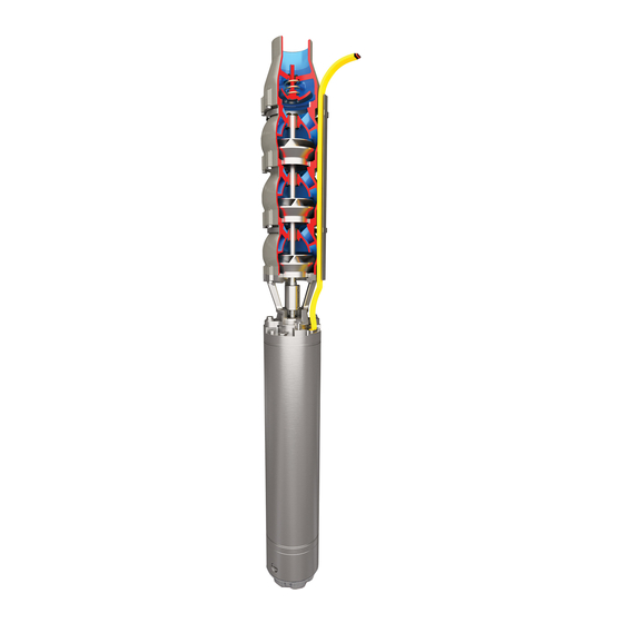
Byron Jackson H2O+ User Instruction – LM028843 EN Submerged motor pumps are in principle submerged in fluid during operation. The fluid jacket has a dampening impact so that the noise pressure level of the units is lower or equal to 70 dB(A). Noise generation from pipelines and valves must be evaluated by the system designer or those putting it into operation. - Page 12 Byron Jackson H2O+ User Instruction – LM028843 EN Figure 3.1: Submersible Pump and Motor Assembly Page 11 of 54...
-
Page 13: Design And Function Description
• Cable banding or brackets to fasten the motor power cable onto the riser pipe NOTE: Not all components or sub-assemblies of a pumping unit are necessarily supplied by Flowserve or part of this delivery. These user instructions apply only to the components or sub-assemblies supplied by Flowserve in this delivery. - Page 14 Riser pipe is also called discharge tubing or column pipe. The riser pipe is not typically supplied by Flowserve. It can be constructed in numerous forms such as steel piping, PVC piping, flexible tubing, etc. Riser pipe is assembled to the non-return valve or top pump bowl and the entire submersible pump/motor assembly is suspended from this riser pipe.
- Page 15 Byron Jackson H2O+ User Instruction – LM028843 EN Figure3.2: Diagram of Typical Water Well System Page 14 of 54...
-
Page 16: Connections
Byron Jackson H2O+ User Instruction – LM028843 EN 3.3 Connections 3.3.1 Electrical connections Electrical connections must be made by a qualified electrician in accordance with relevant local, national and international regulations. It is important to be aware of the EUROPEAN DIRECTIVE on potentially explosive areas where compliance with IEC60079-14 is an additional requirement for making electrical connections. - Page 17 Most modern inverters use IGBT’s which can present rapidly peaking high voltage spikes that can stress the motor insulation windings. These peaks can be exacerbated by long cables typically used in submersible applications. Flowserve strongly recommends the use of an output filter to protect the motor insulation.
- Page 18 Byron Jackson H2O+ User Instruction – LM028843 EN 3.4.3 Motor connection Diagrams Clockwise rotation Direct-on-line-starting – one Star-delta-starting Direct-on-line-starting-delta power supply cable connection in control panel Direct-on-line-starting – two Direct-on-line-starting-star Single-phase motor power supply cable connection in control panel Page 17 of 54...
- Page 19 Byron Jackson H2O+ User Instruction – LM028843 EN Counter-Clockwise rotation Direct-on-line-starting – one Star-delta-starting Direct-on-line-starting-delta power supply cable connection in control panel Direct-on-line-starting – two Direct-on-line-starting-star Single-phase motor power supply cable connection in control panel Page 18 of 54...
- Page 20 Byron Jackson H2O+ User Instruction – LM028843 EN Note: Certain motors (see below table 3.4.3.1) require to be connected in a delta connection. The delta connection is made in the junction box as indicated in Figure 3.4.4 Voltage Motor kW Rating HP Rating 400V 50 Hz...
-
Page 21: Accessories
Immediately after receipt of the equipment, check the delivery/shipping documents for completeness of the shipment and verify there has been no damage in transportation. Any shortage and/or damage must be reported immediately to Flowserve. Check any crates, boxes and wrappings for any accessories or spare parts that may be packed separately with the equipment or attached to side walls of the box or equipment. -
Page 22: Transportation
Byron Jackson H2O+ User Instruction – LM028843 EN Do not remove the protection cover from the pump discharge until installation in the well as it prevents contamination of the pump. In general, care is to be taken when removing crating, coverings, and strapping in order not to damage any auxiliary equipment and/or the paint finish. - Page 23 Byron Jackson H2O+ User Instruction – LM028843 EN When assessing the diameter of the unit, use the smaller size from the pump and motor. This can be found on the rating plate or the data sheet. Under no circumstances must the power cables be used for lifting or moving the motor. Page 22 of 54...
-
Page 24: Storage
Byron Jackson H2O+ User Instruction – LM028843 EN 4.3 Storage 4.3.1 General remarks CAUTION Store the pump and motor vertically and properly secured to prevent their tipping over in a clean, dry location away from vibration. Leave piping connection covers in place to keep dirt and other foreign material out of pump casing. -
Page 25: Installation
The safety specifications must be in accordance with the current regulations at all times. 5 Installation This equipment is intended for installation and operation in vertical orientation only. Flowserve should be contacted to ensure the equipment is suitable for any installation in a horizontal application 5.1 Inspection and preparation Conduct an inspection of the equipment and the facility where it is to be installed. -
Page 26: Installation
Byron Jackson H2O+ User Instruction – LM028843 EN CAUTION Take special care when handling the pump unit. Make certain that it does not hit against walls, steel structures or floors etc. 5.1.1 Insulation Resistance Testing This test will be conducted on a number of different steps during installation or storage inspection of the motor, cable, or other electrical components. - Page 27 Required minimum flow velocity past the motor as per Table 5.2.2.1. For applications requiring lower flow velocities, Flowserve should be contacted for application review and approval to operate at the lower velocity. Generally, Flowserve will require a flow shroud to ensure velocity is above the minimum.
- Page 28 • Your motor is designed to operate in applications with water temperatures of 50°C (122°F) or less. Please contact your Flowserve representative if the application temperature is hotter for recommendations. Page 27 of 54...
- Page 29 Byron Jackson H2O+ User Instruction – LM028843 EN • The pump must have adequate depth in the well to ensure adequate submergence including when the water level draws down after pumping commences. • In addition to pump depth, the cable splice to the motor leads should be submerged to ensure adequate cooling of the leads.
- Page 30 Byron Jackson H2O+ User Instruction – LM028843 EN 5.2.3 Antifreeze General Information about Filling. The General information about filling in this section applies to all motor types, unless stated otherwise in the individual descriptions. Motors are usually delivered pre-filled with water only If a motor must be filled or topped up with a mixture of water and antifreeze, this must be prepared in a clean container before filling the motor.
- Page 31 Byron Jackson H2O+ User Instruction – LM028843 EN Remove the filling hole screw/plug (PT 100 Tap) located near the top end of the motor. Fill the water thru PT100 tap by placing the motor at 45 deg. Dismantle the tap of check valve and fill the water Bring the motor to horizontal position Measure the value using Vernier.
- Page 32 The motor leads must be connected to the power cable securely and in a manner that will ensure water tight sealing of the connection to ensure electrical integrity. Failure to make this connection properly will lead to premature failure of the system. Flowserve recommends this work be done by professionals only who have been Page 31 of 54...
- Page 33 Byron Jackson H2O+ User Instruction – LM028843 EN trained in the procedures required to achieve a successful and reliable submersible splice. Splice kits can be obtained, and the kit should provide the procedure for completing the splice. Meg Test post splicing and prior to install and confirm the insulation resistance is at least the value indicated in Table 5.2.4.
-
Page 34: Impeller Lift Requirement
Byron Jackson H2O+ User Instruction – LM028843 EN 5.3 Impeller Lift Requirement Fig 5.3 Typical Pump and Motor Connection If the pump was not supplied assembled to the motor, then proper impeller lift is required. This is usually accomplished by the motor shaft lifting the pump shaft from its lowest position. Typical pump lift should be 3mm (0.12 in.) or according to the pump manufacturer’s requirements. - Page 35 Byron Jackson H2O+ User Instruction – LM028843 EN Fig 5.4 Typical Cross-sectional drawing Page 34 of 54...
-
Page 36: Connecting Pump To Motor
Byron Jackson H2O+ User Instruction – LM028843 EN MATERIAL REF. NO. DESCRIPTION 1100 DISCHARGE CASING ASTM A743 CF8 (304SS) 1170 BOWL ASTM A743 CF8 (304SS) 1232 CLAMPS FOR CABLE GUARD 1340 INTERCONNECTOR ASTM A743 CF8 (304SS) 1471 IMPELLER ADAPTER PLATE ASTM A743 CF8 (304SS) 1630 VALVE BUSH - FABRICATION... -
Page 37: Installation After Pump And Motor Have Been Assembled Together
Byron Jackson H2O+ User Instruction – LM028843 EN b) Install set screw (6569.1) into coupling (7000) to lock the position on the motor shaft. Check motor direction of rotation using a phase rotation meter. c) Measure and write down pump manufacturer recommended impeller lift setting for final confirmation. - Page 38 Byron Jackson H2O+ User Instruction – LM028843 EN b) During lowering, the unit must always hang freely and must not become wedged in the well shaft. Always ensure that the pump/motor/tubing string can be rotated freely in the well during the entire installation. Attach a cable clip every 3 m (approx.
- Page 39 Byron Jackson H2O+ User Instruction – LM028843 EN 5.5.3 Fastener Installation Fastener Torques Page 38 of 54...
-
Page 40: Commissioning
Byron Jackson H2O+ User Instruction – LM028843 EN 6 Commissioning 6.1 Safety instructions NOTE Before commissioning, operation or shutdown of the pumping unit, read Section 2 “Safety Information” CAUTION These operations must be carried out by fully qualified personnel. Turn off power supply for safety while pump commissioning is in progress. - Page 41 Starting, including for test purposes, is never allowed if the pump is not submerged. • For the minimum submersion depth in the delivery medium, refer to the Section 9 “Technical Data” or ask Flowserve. • Failure to follow these restrictions can cause the following dangers:...
- Page 42 Motor protection settings that do not follow these guidelines could cause unsafe conditions or premature failure of your equipment. Please note, data sheet may have been supplied with quote or may be shipped with equipment. If required, consult your Flowserve representative for setting these limitations. Control setting Minimum...
- Page 43 Byron Jackson H2O+ User Instruction – LM028843 EN 2) Verify that balanced three-phase voltage is supplied and is at least 95% of nameplate voltage. CAUTION Never attempt to run the pumping unit with an unbalanced voltage between two leads. An imbalance between two leads can cause 6-10 times of imbalances in an amperage and the resultant temperature increase means a decrease in motor life.
-
Page 44: Operation
Byron Jackson H2O+ User Instruction – LM028843 EN During first-time start-up, take notice of the following: a) When motor is started direct on line, it should attain full speed within 3 seconds. If after this period the line current is still high (over twice normal value), the pumping unit is not attaining the full speed. - Page 45 Byron Jackson H2O+ User Instruction – LM028843 EN 4) Verify that the pump motor comes up to speed within 3 seconds as indicated by normal readings of current, voltage, head and flow. 5) If one of the following conditions occurs a) current exceeds the rated value of the amperage or b) voltage varies + 10 % or - 10 % from the rated value or c) head and flow are abnormal...
- Page 46 If this problem cannot be cured by well work, contact Flowserve for devices that can be added to the pumping unit to prevent its sanding up.
- Page 47 Byron Jackson H2O+ User Instruction – LM028843 EN 7.1.3 Motor operation • Always check the motor insulation resistance (megger) before resetting a tripped circuit breaker. • Wait 10 minutes before restarting the motor. • Breaking suction due to inadequate water level in the well can cause pump and motor damage and thus renders warranty void.
-
Page 48: Shut Down
Byron Jackson H2O+ User Instruction – LM028843 EN 7.1.4 Number of starts Size Allowable Starts/hour 6” All other motors Table 7.1 Allowable starts Excessive starting of your submersible pumping unit can result in a shorter life and damage to the equipment. - Page 49 Byron Jackson H2O+ User Instruction – LM028843 EN The intake strainer if blocked with debris Remove pump and clean the strainer Pump or check valve passages are blocked Remove pump and correct the issue Motor is turning at a slower speed Ensure proper voltage is being applied during operation Pump shaft or coupling is damaged/broken...
- Page 50 Check insulation resistance and pull unit if too low. Note: In the event the pump or motor needs to be repaired, spare parts should be ordered from Flowserve. Use of non-Flowserve parts could result in numerous risks and non-compliance with safety and performance requirements.
-
Page 51: Returns And Disposal
3. Close the openings of the pump properly 4. Pack the pump securely for transport and send it to the service department. NOTICE Pumps sent to a FLOWSERVE service department will only be unpacked and opened with a correctly filled corresponding declaration of decontamination. Disposal and recycling At the end of the equipment service life, the relevant materials and parts should be recycled or disposed of using local environmental regulation methods. -
Page 52: Annex A: Declaration Of Conformity
Annex A: Example Declaration of Conformity for CE Marked Pumps EU Declaration of Conformity - Original - The manufacturer: Flowserve Pumps, Flowserve GB Ltd. Hawton Lane, Newark, Notts NG24 3BU, United Kingdom declares herewith that the product Pumpset consisting of:... - Page 53 Annex B: Example Declaration of Conformity for UKCA Marked Pumps UKCA Declaration of Conformity - Original - The manufacturer: Flowserve Pumps, Flowserve GB Ltd. Hawton Lane, Newark, Notts NG24 3BU, United Kingdom declares herewith that the product Pumpset consisting of:...
-
Page 54: Appendix
Byron Jackson H2O+ User Instruction – LM028843 EN 10 Appendix Page 53 of 54... - Page 55 Flowserve Corporation has established industry leadership in the design and manufacture of its products. When properly selected, this Flowserve product is designed to perform its intended function safely during its useful life. However, the purchaser or user of Flowserve products should be aware that Flowserve product might be used in numerous application under a wide variety of industrial service conditions.
Need help?
Do you have a question about the Byron Jackson H2O+ and is the answer not in the manual?
Questions and answers