Table of Contents
Advertisement
Quick Links
TRANSLATION OF THE ORIGINAL VERSION
Operating Manual
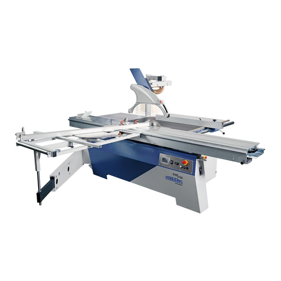
Sliding Table Saw PANHANS - 690|100
Sliding Table Saw 690|100
Machine Type:
HOKUBEMA Maschinenbau GmbH
Graf-Stauffenberg-Kaserne, Binger Str. 28 | Halle 120
DE 72488 Sigmaringen | Tel. +49 07571 755-0
E-Mail:
info@hokubema-panhans.de
| Web:
https://hokubema-panhans.de
Advertisement
Table of Contents
Troubleshooting


Need help?
Do you have a question about the 690 and is the answer not in the manual?
Questions and answers