Table of Contents
Advertisement
Quick Links
TRANSLATION OF THE ORIGINAL VERSION
Operating Manual
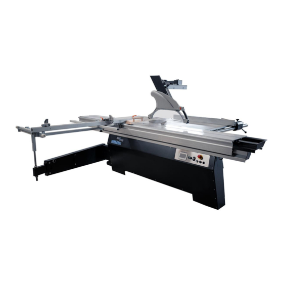
Sliding Table Saw PANHANS - 680|100
Sliding Table Saw 680|100
Machine Type:
HOKUBEMA Maschinenbau GmbH
Graf-Stauffenberg-Kaserne, Binger Str. 28 | Halle 120
DE 72488 Sigmaringen | Tel. +49 07571 755-0
E-Mail:
info@hokubema-panhans.de
| Web:
https://hokubema-panhans.de
Advertisement
Table of Contents
Troubleshooting

Related Manuals for PANHANS 680 100


Summary of Contents for PANHANS 680 100
- Page 1 TRANSLATION OF THE ORIGINAL VERSION Operating Manual Sliding Table Saw PANHANS - 680|100 Sliding Table Saw 680|100 Machine Type: HOKUBEMA Maschinenbau GmbH Graf-Stauffenberg-Kaserne, Binger Str. 28 | Halle 120 DE 72488 Sigmaringen | Tel. +49 07571 755-0 E-Mail: info@hokubema-panhans.de | Web:...
-
Page 2: Table Of Contents
Table of Contents Introduction..............................7 Legal Notice ................................7 Illustrations ................................7 Symbols ................................7 General Symbols ..............................7 Symbols in Safety Instructions ..........................8 General ................................9 Intended Use ................................9 Target Group and Previous Experience ........................9 Requirements for the Operators ..........................9 Accident Prevention .............................. - Page 3 Technical Characteristics ............................23 Emission Levels ..............................24 5.3.1 Noise Emission Values: ..............................24 Dimensions ..............................25 Working Areas............................... 25 Dimensions (Front View) ............................25 Dimensions (Top View) ............................26 Installation and Connection ......................... 27 Check Delivery Conditions ............................ 27 Transport to the Installation Site ..........................
- Page 4 11.4.3 Emergency Stop Switches ..............................43 Operating the 4.7" Touch Display ........................ 44 12.1 Start Screen ................................44 12.2 Status Window ..............................44 12.3 Language Settings ..............................45 12.4 Machine Overview ..............................45 12.5 Saw Blade Calibration ............................45 12.5.1 Calibrate Height ................................
- Page 5 16.3 Retightening / Changing the V-belt ........................64 Maintenance and Inspection ........................65 17.1 Lubrication Guide ..............................65 Options and Accessories ..........................66 18.1 Aggregates ................................66 18.2 Machine Operation ............................... 66 18.3 Optional Fence Systems ............................66 18.4 Slide Table and additional Supports ........................67 18.5 Support Systems ..............................
- Page 6 Figure 41: Start screen ..................................44 Figure 42: Status window ..................................44 Figure 43: Language settings ................................45 Figure 44: Machine overview - current positions and speed ....................... 45 Figure 45: Saw blade height 50 mm..............................46 Figure 46: Calibrate height .................................. 46 Figure 47: Adopt calibration value for height ............................
-
Page 7: Introduction
Introduction This operating manual applies exclusively to the PANHANS sliding table saw type 680|100. The purpose of this document is to acquaint the user with the machine and enable him to use it to the full extent of its intended capabilities. Additional- ly it contains important information to operate the machine safely, properly and economically. -
Page 8: Symbols In Safety Instructions
Symbols in Safety Instructions Symbol Safety Instruction General danger symbol, which requires the highest attention! Failure to observe may result in damage to the equipment, serious injury or even death. Warning of possible danger from forklift traffic! Non-observance may result in life-threatening injuries. Warning indicates a possible hazard under suspended loads! Non-observance may result in life-threatening injuries. -
Page 9: General
All measuring scales are manufactured in accordance with the calibration regulations to accuracy class 2. Intended Use The PANHANS - 680|100 sliding table saw is designed for cutting materials for which the respective saw blade used is suitable (e.g. wood, pressboard, veneer, plastic or aluminium). This machine is not suitable for cutting metal, plastic or scrap wood (which could contain nails, screws and other metal parts). -
Page 10: Accident Prevention
Accident Prevention To avoid accidents, the following rules must be observed for operation: • Prevent unauthorized persons from gaining access to the machine. • Keep unauthorized persons away from the danger areas. • Repeatedly inform present other persons about existing residual risks (see section 4.1.2). •... -
Page 11: Structure And Function
3.6 Structure and Function • PANHANS - 680|100 - Sliding table saw with tiltable saw blade 0 … 46° • Cutting length of slide table = 3400 mm -> slide table length = 3200 mm • Table top surface size: 655 mm x 1200 mm •... -
Page 12: Special Equipment
3.8 Special Equipment A wide range of special accessories and optional components are available for the sliding table saw type 680|100. These allow you to expand your machine individually. Detailed information and the corresponding article numbers can be found in chapter 18. 3.9 Expandability The machine is prepared for the later addition of special accessories (see chapter ... -
Page 13: Safety
4.1.1 Application Area and Intended Use The PANHANS 680|100 sliding table saw is used exclusively for cutting materials for which the saw blade used is suitable (e.g. wood, chipboard, veneer, plastic and aluminium). This sliding table saw is not suitable for cutting metal, plastic or scrap wood (which may contain nails, screws etc.). -
Page 14: Residual Risks
4.1.3 Residual Risks The machine is built according to the latest state of the art and the recognised safety rules. Nevertheless, the use of the machine may cause danger to life and limb of the user or third parties or damage to the machine and other equipment. -
Page 15: Observe The Environmental Protection Regulations
Be aware of the risk of crushing between the slide table and the holding block for the saw blade. Be aware of the risk of crushing at the end of the running rail for the slide table between the run- ning rail and the slide table. -
Page 16: Organisational Measures
4.1.5 Organisational Measures Always keep this operating manual within easy reach and at the place of use of the machine. In addition to the operating manual, observe and instruct on generally applicable legal and other binding regulations for accident prevention and environmental protection. Supplement the operating manual with further instructions, including supervisory and reporting duties, to take account of special operational features (e.g. -
Page 17: Special Work Within The Scope Of Maintenance Work As Well As Troubleshooting In The Workflow
Switch off the machine even during short work interruptions! Switch off the control voltage and main switch before leaving the machine. Never leave the machine unat- tended in an unsecured state. 4.2.2 Special work within the Scope of Maintenance Work as well as Troubleshooting in the Workflow Observe maintenance and inspection activities prescribed in the operating manual! These activities, as well as all other repair work, may only be carried out by qualified personnel! - Page 18 • If a second person is working at the sliding table saw to remove processed workpieces, this person must not stand at any other place than at the end of the table extension. • Use a ram plate on the slide table when “trimming”. •...
-
Page 19: Hazardous Areas On The Sliding Table Saw
Hazardous Areas on the Sliding Table Saw Carry out adjustment work within the danger zones only when the saw blade is stationary! 4.4.1 Danger Zone Saw Blade • The area 120 mm around the saw blade is con- sidered to be a danger area with an increased risk of injury. -
Page 20: Avoidance Of Kickback Hazards
Avoidance of Kickback Hazards Uncontrolled kick-back of workpieces and parts must be prevented with all available means, as these provide a very high hazard potential. The kickback area starts from the centre of the saw blade towards the rear, where the saw teeth rotate in an upward direction. -
Page 21: Parallelism Of The Rip Fence
4.5.4 Parallelism of the rip fence Regularly check the parallelism of the fence by measuring the front and rear of the machine table. Even a slight deviation of 1 to 2 degrees can press the workpiece against the saw blade in such a way that it jams. Then it can be caught by the rising teeth and trigger a kickback. -
Page 22: Effect Of Cooling Lubricants On Polycarbonate
4.6.1 Effect of cooling lubricants on polycarbonate The ingredients in cooling lubricants can negatively influence the material properties of polycarbonate. When cooling lubricants are used regularly (e.g. when machining aluminium), the polycarbonate guards should be renewed every 2 years at the latest. Even if there is no externally visible damage, the material may no longer have the required impact protection. -
Page 23: Technical Characteristics
Technical Characteristics • Sliding table saw for trimming, cutting to length, sizing, mitre cutting, etc. • Dimensionally stable and self-supporting machine body • Torsion-resistant and finely planed cast iron table top • Robust and powerful saw unit for precise saw cuts •... -
Page 24: Emission Levels
Emission Levels Noise Information: The values given are emission levels and therefore do not necessarily represent safe workstation values at the same time. Although there is a correlation between emission and immission levels, it cannot be reliably de- duced whether additional precautionary measures are necessary or not. Factors that may affect the current immission level at the workstation include the duration of exposure, the nature of the workspace, other noise sources (e.g. -
Page 25: Dimensions
Dimensions Working Areas = Working area = Removal area Figure 7: Working areas Dimensions (Front View) Figure 8: Dimensions (front view) BA_PH_680-100_EN_08-22.docx... -
Page 26: Dimensions (Top View)
Dimensions (Top View) Sliding table Table length / Cutting length Option 2600 mm / 2850 mm Standard 3200 mm / 3450 mm Option 3800 mm / 4050 mm A = Aperture Cutting width / Aperture width Option 830 mm / 880 mm Standard 1030 mm /... -
Page 27: Installation And Connection
and Connection 7 Installation Check Delivery Conditions Check the consignment for completeness and possible transport damage. In case of transport damage, please keep the packaging and inform the shipping company and the manufacturer immediately! Later complaints cannot be accepted. Transport to the Installation Site •... -
Page 28: Levelling With A Spirit Level
• Level unevenness of the floor by means of the stand adjusting screws (see next section 7.3). Dispose of the packaging material in an environmentally friendly way! Levelling with a Spirit Level Caution: Ensure that all four feet are firmly on the floor, evenly loaded and the machine is levelled with a spirit level. -
Page 29: Lashing On A Transport Vehicle
Lashing on a Transport Vehicle For transporting the palletised machine on a transport vehicle, a lashing point (Z) is attached to each of the four 4 sides of the machine. A separate lashing strap must be used for each lashing point (Z). All 4 lashing straps must be individually tensioned on the loading area! The responsibility for safe loading is borne by the respective shipper! Figure 13: Lashing points (4 x) -
Page 30: Connecting The Extraction Unit
Connecting the Extraction Unit The air velocity must be checked before initial commissioning and after significant changes. The extraction system must be checked daily for obvious defects after initial commissioning and monthly for effectiveness. The machine must be connected to an effective extraction system on-site. -
Page 31: Electrical Connection
Electrical Connection The electrical connection must be carried out by an authorised electrician! The electrical circuit diagrams are located in the control cabinet. Please observe the specified nominal voltage 400 VAC / 50 Hz (3 phases / N / PE)! Connection to the mains (3 phases) is made at the terminal strip in the terminal box. -
Page 32: Components & Controls
Components & Controls Figure 17: Components & controls - front view Figure 18: Components & controls - oblique view Description Description Saw blade guard with suction Control panel Swivel arm for saw blade guard Touch display (for height / angle / speed) Riving knife Machine body Sliding shoe... -
Page 33: Figure 19: Components & Controls - Top View
Figure 19: Components & controls - top view Description Description Aluminium profile rail for rip fence Cross slide Rip fence Cross slide pull-out Mechanical rip fence guide Cross slide clamping lever Clamping lever for profile rail Cross slide hook-in bar Safety catch for saw blade change Cross slide guide Remote locking for slide table... -
Page 34: Mounting And Usage
Mounting and Usage 10.1 Slide Table When the sizing and trimming circular saw is delivered, the trolley is already fitted ready for operation. • Loosen (pull out) the remote locking device (21). • Move the slide table to the desired position. •... -
Page 35: Operating The Rip Fence
Set the aluminium profile rail for normal cuts: • Push the aluminium profile rail (4) as far as it will go onto the two fixing bolts (3) of the holding block. The cross-section must look as shown in the photo on the left. •... -
Page 36: Mounting The Cross Slide
10.3 Mounting the Cross Slide Figure 24: Cross slide mounting Figure 25: Cross slide clamping • Pull the slide table into the rearmost position and bring the swivel arm (6) into position. • Lift the cross slide (22) with 2 persons and place it on the support (A) for the cross slide. •... -
Page 37: Use Cross-Cut Fence For 90° Cuts
10.4 Use Cross-Cut Fence for 90° Cuts Figure 27: Mount cross-cut fence Figure 28: Cross-cut fence at zero position Figure 30: Abut guide bolt to the angle stop plate Figure 29: Prepare 90 degree cut • Place the cross-cut fence (13) on the cross slide (22). At the same time insert the pivot bearing (D) from the cross-cut fence (13) into the locking guide (U) of the cross slide (22) as shown in ... -
Page 38: Use Cross-Cut Fence For Angle Cuts
10.5 Use Cross-Cut Fence for Angle Cuts The cross-cut fence is used to guide the workpiece during cutting. Cutting lengths and angles can be variably adjusted. Procedure for setting the cross-cut fence (e.g. setting to 15° and 93 cm): Figure 31: Set angular cuts Figure 32: Adjusting the cross-cut fence 10.5.1 Set cutting angle to 15°... -
Page 39: Use Further Flip Stops
10.5.3 Use further flip stops The sliding table saw is equipped with a total of 3 flip stops: 1. Front flip stop (Y) for lengths up to 1900 mm 2. Middle flip stop (M) for lengths between 1900 and 2100 mm 3. -
Page 40: Readjusting The Fence Rulers
10.6 Readjusting the Fence Rulers If the cutting dimensions no longer correspond to the set length, the measuring scales for the cross-cut fence can be readjusted. For this purpose, the rulers can be moved back to the exact position manually after loosen- ing the fixing screws (F) on the bottom side. -
Page 41: Swivelling Saw Blade Guard
10.7 Swivelling Saw Blade Guard Working position: • Swivel the guard forwards and tighten the clamping screw in a ↻ clockwise direction. Do not use tools! Figure 38: Swivel arm for saw blade guard Swivel away: • Press lever (1) or (2) backwards and swivel the saw blade guard to the left or right. •... -
Page 42: Commissioning
Commissioning Please observe the accident prevention regulations! Before switching on, check that • there are no loose parts on the tabletop and that all tools have been removed, • the riving knife is correctly adjusted and the sawdust flap is closed, •... -
Page 43: Safety Equipment
11.4 Safety Equipment The machine is equipped with the following safety systems: 11.4.1 Saw Blade Guard with Extraction The swivelling guard has a lowerable protective bonnet with interchangeable insert (for wide and narrow) and a suction port. The guard thus ensures both effective extraction of chips and sawdust and an effective saw blade protection. -
Page 44: Operating The 4.7" Touch Display
Operating the 4.7" Touch Display The 4.7" touch display visualises the height and tilt of the saw blade as well as the selected speed. 12.1 Start Screen Figure 41: Start screen • To be able to operate the machine, press the “Machine” symbol (see section 12.4). •... -
Page 45: Language Settings
12.3 Language Settings Figure 43: Language settings • After selecting the flag symbol, the screen shown above appears. • To change the language, simply select the desired flag symbol. • The new language is saved automatically (no confirmation required). • Press the “Home” button to return to the main menu). 12.4 Machine Overview After pressing the “Machine”... -
Page 46: Calibrate Height
12.5.1 Calibrate Height • Important: Set the saw blade tilt to an angle of exactly 0.0° using the positioning keys. • Switch off and secure the main switch on the control cabinet. • Then turn the stationary saw blade by hand so that one saw tooth is exactly at the top in the centre of the axis. -
Page 47: Calibrate Angle
12.5.2 Calibrate Angle • Move the saw blade set to 0° to the uppermost position • Then switch off the main switch and secure or lock it. • Use a 90° stop angle to check that the saw blade is square. •... -
Page 48: Date And Time (From Software Version 1.9)
12.6 Date and Time (from software version 1.9) From software version 1.9, the touch display also has a date and time function. Show date and time: • Tap on the HOKUBEMA logo → The current time is displayed • Tap on the time displayed →... -
Page 49: Changing The Saw Blade
Changing the Saw Blade Work at the saw blades must always be carried out with extreme care. There is an increased risk of injury due to the very sharp cutting edges! Protective gloves must be worn when changing saw blades! 14.1 Remove Saw Blade Figure 54: Remote locking on the slide table Figure 55: Safety catch on the slide table... -
Page 50: Insert Main Saw Blade
14.2 Insert Main Saw Blade • Clean flange and saw blade. • Insert the new saw blade and mount the flange (observe the direction of rotation!) • Screw in the clamping screw by hand as far as it will go (left-hand thread!). •... -
Page 51: Optional Components
Optional Components 15.1 Digital Cross-Cut Fence The optional digital cross-cut fence has three stop ele- ments, each equipped with its own battery-powered digital indicator. The corresponding flip stop is clamped using the hand- wheel next to the digital indicator (see Figure 59). •... -
Page 52: Change / Enter Reference Value
15.2.1 Change / Enter Reference Value For certain applications it may be necessary to store a specific reference dimension. This section explains the procedure for changing the reference dimension to the example value of 1150.0 mm: Step 1 Step 2 ENTER INCR INCR... -
Page 53: Rip Fence Left To The Saw Blade
15.3 Rip Fence left to the Saw Blade For cutting long, narrow parts such as cupboard doors, the machine can be equipped with a “rip fence to the left of the saw blade”. Structure and operation: • Move the cross-cut fence to the desired length (max. -
Page 54: Digit Pab - Absolute Measuring System For The Rip Fence
15.5 Digit PAB - Absolute Measuring System for the Rip Fence The Digit-PAB is a cordless, battery-operated absolute measuring system for the manually adjustable rip fence. The current position value is visualised via an easy-to- read digital display, which is housed in a swivelling housing on the rip fence. -
Page 55: Power Feeder 76
15.6 Power Feeder 76 The circular saw power feeder 76 (Art. No. 2078) is the ideal addition to your sliding table saw. It ensures additional safety and ergonomic working when cutting battens, planks, window scantlings and other work- pieces made of solid wood. It is simply pushed onto the rip fence holding block (1) via the guide rail instead of the standard rip fence rail and fixed via the clamping lever. -
Page 56: Adjustable Scoring Saw Blade "Quickstep
15.7 Adjustable Scoring Saw Blade “QuickStep” Technical Specifications of the scoring saw blade Art. No. 4550 Speed range: 8000 - 12100 rpm Saw blade: Ø 125 mm Setting range: 2.8 – 3.8 mm Raster: 0,05 mm Flange: Ø 70 mm Drilling: Ø... -
Page 57: Figure 77: Quickstep Quick-Release Screw
Installing: • Clean all parts thoroughly. • Insert the saw blades into the bolts on the flanges, observing the direction of rotation (D), see Figure 76. • Screw in and tighten the screws (4 per flange). • Screw the flanges together until the saw blades touch; for the (approx. 5) last turns pull the knurled screw forward. -
Page 58: Manual Scoring Unit 1750
15.8 Manual Scoring Unit 1750 Work at the saw blades must always be carried out with extreme care. There is an increased risk of injury due to the very sharp cutting edges! Protective gloves must be worn when changing saw blades! •... -
Page 59: Adjusting The Manual Scoring Saw
15.8.1 Adjusting the manual scoring saw On machines with manual scoring unit 1750 (option), the scoring saw is adjusted using the setting wheels shown in the figure. These are located on the front of the machine. • Height adjustment: Adjust the desired height using the setting wheel (1) •... -
Page 60: Laser Cut-Position Indicator
15.10 Laser Cut-Position Indicator As an additional positioning aid for the workpiece, the sliding table saw can be equipped with a laser cut-position indicator (Art. No. 4322). This is particularly useful for visually indicating the kerf on tear-off or trim cuts, e.g. for board material with a forest edge. -
Page 61: Swivel-Away Device For The Cross Slide
15.13 Swivel-Away Device for the Cross Slide For some operations it may be necessary to remove the cross slide. For this purpose, the optional swivel-away device available under Art. No. 4770 is a useful aid. 15.13.1 Attaching the swivel arm to the cross slide •... -
Page 62: Troubleshooting
Troubleshooting 16.1 General Faults Proceed systematically when searching for the cause of a malfunction. If you are unable to find the fault or to remedy the malfunction, contact our customer service department (phone number: 0049 7571 / 755 – 0). Before you call us, please follow these steps: •... -
Page 63: Fault Messages On The Touchscreen
16.2 Fault Messages on the Touchscreen Message: E-Stop pressed! • An emergency stop switch was actuated. Cause: • Check the two emergency stop switches. Remedy: Figure 86: Error message 1 Message: Motor protection! • Motor protection switch F1 or F2 has tripped. •... -
Page 64: Retightening / Changing The V-Belt
16.3 Retightening / Changing the V-belt Before starting work, the main switch must be switched off and secured with a padlock against being switched on again unexpectedly. Procedure: • First flip the lever (H) to release the tension of the V-belt. •... -
Page 65: Maintenance And Inspection
Maintenance and Inspection Before any maintenance and inspection work is carried out, chapter 4 Safety must be read carefully and observed! Operational malfunctions caused by insufficient or improper maintenance can result in very high repair costs and long machine downtimes. Regular maintenance is therefore essential. Due to the different operating conditions, it is not possible to determine in advance how often a wear check, inspection or maintenance is required. -
Page 66: Options And Accessories
Options and Accessories 18.1 Aggregates Article Description Art. No. THREE-PHASE MOTOR More powerful main saw motor, instead of the standard 5.5 kW motor. 4319 WITH 7.5 KW (10 HP) SCORING UNIT 1750 With manual height and lateral adjustment via externally mounted 4078 0.55 KW (0.75 HP) handwheels with "APA"... -
Page 67: Slide Table And Additional Supports
Continuation “18.3 Optional Fence Systems” Article Description Art. No. Digital wireless absolute measuring system (battery operated) for the DIGIT-PAB FOR rip fence, manual adjustment; with swivelling indicator on the fence, CUTTING WIDTH fine adjustment to 0.1 mm; no additional calibration is required, even if 4755 1030 MM the fence has been swivelled under the table. -
Page 68: Support Systems
18.5 Support Systems Article Description Art. No. ADDITIONAL SUPPORT 4786 Can be hooked on the slide table, length 500 mm FOR LARGE PLATES Adjustable as table extension in the infeed or outfeed area, attached SWIVEL TABLE SUPPORT 4768 WITH PLASTIC ROLLER to the aluminium double slide table SWIVEL-AWAY DEVICE 4770... -
Page 69: Disassembly And Scrapping
Disassembly and Scrapping When dismantling and scrapping the machine, the current EU regulations or the respective regulations and laws of the country of operation, which are prescribed for proper dismantling and disposal, must be observed. The aim is to dismantle the machine and its various materials and components properly, to recycle all possible parts and to dispose of non-recyclable components in the most environmentally friendly way. -
Page 70: Eu - Declaration Of Conformity
EU - Declaration of Conformity in accordance with the EU Machinery Directive 2006/42/EC Annex II A The manufacturer, HOKUBEMA Maschinenbau GmbH Graf-Stauffenberg-Kaserne Binger Str. 28 | Halle 120 Phone: +49 (0) 7571 / 755 - 0 DE 72488 Sigmaringen (Germany) Fax: +49 (0) 7571 / 755 - 222 hereby declares that the manufactured machine...
Need help?
Do you have a question about the 680 100 and is the answer not in the manual?
Questions and answers