Table of Contents
Advertisement
Quick Links
TRANSLATION OF THE ORIGINAL VERSION
Operating Manual
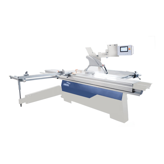
Sliding Table Saw PANHANS - 690|200
Sliding Table Saw 690|200
Machine Type:
HOKUBEMA Maschinenbau GmbH
Graf-Stauffenberg-Kaserne, Binger Str. 28 | Halle 120
DE 72488 Sigmaringen | Tel. +49 07571 755-0
E-Mail:
info@hokubema-panhans.de
| Web:
https://hokubema-panhans.de
Advertisement
Table of Contents
Troubleshooting

Subscribe to Our Youtube Channel
Related Manuals for PANHANS 690|200


Summary of Contents for PANHANS 690|200
- Page 1 TRANSLATION OF THE ORIGINAL VERSION Operating Manual Sliding Table Saw PANHANS - 690|200 Sliding Table Saw 690|200 Machine Type: HOKUBEMA Maschinenbau GmbH Graf-Stauffenberg-Kaserne, Binger Str. 28 | Halle 120 DE 72488 Sigmaringen | Tel. +49 07571 755-0 E-Mail: info@hokubema-panhans.de | Web:...
-
Page 2: Table Of Contents
Table of Contents Introduction..............................8 Legal Notice ................................8 Illustrations ................................8 Symbols ................................8 General Symbols ..............................8 Symbols in Safety Instructions ..........................9 General ................................. 10 Intended Use ................................. 10 Target Group and Previous Experience ......................... 10 Requirements for the Operators ........................... 10 Accident Prevention .............................. - Page 3 Emission Levels ..............................25 5.3.1 Noise Emission Values: ..............................25 Dimensions ..............................26 Working Areas............................... 26 Dimensions (Front View) ............................26 Dimensions (Top View) ............................27 Installation and Connection ......................... 28 Check Delivery Conditions ............................ 28 Transport to the Installation Site .......................... 28 Levelling with a Spirit Level ...........................
- Page 4 13.4 Set Date and Time ..............................42 Operating the Rip Fence ..........................43 14.1 Rip Fence Positioning ............................43 14.2 Folding away the rip fence ............................ 44 14.3 Calibrating the Rip Fence ............................44 14.4 Changing the Rip Fence Offset Value ........................45 14.5 Pinch Protection on the Rip Fence ........................
- Page 5 20.4.2 Super Gehrfix I Operation ..............................61 20.4.3 Attach Cross-Cut Fence ..............................61 20.4.4 Set Length > 1885 mm ..............................61 20.4.5 Set Angle to 90 Degrees ..............................61 20.4.6 Setting Degrees & Intermediate Degrees ........................62 20.5 Cross-Cut & Mitre Fence Super Gehrfix II ......................62 20.5.1 Features...................................
- Page 6 Disassembly and Scrapping .......................... 82 EU - Declaration of Conformity ..........................83 List of Figures Figure 1: Saw blade ....................................8 Figure 2: Danger zone saw blade ................................. 20 Figure 3: Danger zones around the machine ............................20 Figure 4: Cutting short workpieces to width ............................21 Figure 5: Fixing the deflector wedge on the table ..........................
- Page 7 Figure 57: Fold sawdust flap forwards ..............................53 Figure 58: Saw blade flange ................................. 53 Figure 59: Riving knife setting (symbolic representation)........................54 Figure 60: Tele-Digit cross-cut fence..............................55 Figure 61: Fixing points on the cross slide ............................55 Figure 62: Tele-Digit components ................................ 56 Figure 63: Digital indicator ...................................
-
Page 8: Introduction
Introduction This operating manual applies exclusively to the PANHANS sliding table saw type 690|200. The purpose of this document is to acquaint the user with the machine and enable him to use it to the full extent of its intended capabilities. Additional- ly it contains important information to operate the machine safely, properly and economically. -
Page 9: Symbols In Safety Instructions
Symbols in Safety Instructions Symbol Safety Instruction General danger symbol, which requires the highest attention! Failure to observe may result in damage to the equipment, serious injury or even death. Warning of possible danger from forklift traffic! Non-observance may result in life-threatening injuries. Warning indicates a possible hazard under suspended loads! Non-observance may result in life-threatening injuries. -
Page 10: General
All measuring scales are manufactured in accordance with the calibration regulations to accuracy class 2. Intended Use The PANHANS - 690|200 sliding table saw is designed for cutting materials for which the respective saw blade used is suitable (e.g. wood, pressboard, veneer, plastic or aluminium). This machine is not suitable for cutting metal, plastic or scrap wood (which could contain nails, screws and other metal parts). -
Page 11: Accident Prevention
Accident Prevention To avoid accidents, the following rules must be observed for operation: • Prevent unauthorized persons from gaining access to the machine. • Keep unauthorized persons away from the danger areas. • Repeatedly inform present other persons about existing residual risks (see section 4.1.3). •... -
Page 12: Structure And Function
The cross cut fence has continuous scales and an adjustable slide. It can be extended to 3200 mm and can be used on both sides of the cross slide. The rip fence with a quick clamp can be adjusted to any dimension up to 1250 mm. -
Page 13: Special Equipment
A wide range of special accessories and optional components are available for the sliding table saw type 690|200. These allow you to expand your machine individually. Detailed information and the corresponding article numbers can be found in chapter 23. -
Page 14: Safety
4.1.1 Application Area and Intended Use The PANHANS 690|200 sliding table saw is used exclusively for cutting materials for which the saw blade used is suitable (e.g. wood, chipboard, veneer, plastic and aluminium). This sliding table saw is not suitable for cutting metal, plastic or scrap wood (which may contain nails, screws etc.). -
Page 15: Residual Risks
4.1.3 Residual Risks The machine is built according to the latest state of the art and the recognised safety rules. Nevertheless, the use of the machine may cause danger to life and limb of the user or third parties or damage to the machine and other equipment. -
Page 16: Observe The Environmental Protection Regulations
Be aware of the risk of crushing at the end of the running rail for the slide table between the run- ning rail and the slide table. Pay attention to the risk of crushing on the inside of the slide table on fixed components / guide rail (2x) on the inside of the slide table. -
Page 17: Organisational Measures
4.1.5 Organisational Measures Always keep this operating manual within easy reach and at the place of use of the machine. In addition to the operating manual, observe and instruct on generally applicable legal and other binding regulations for accident prevention and environmental protection. Supplement the operating manual with further instructions, including supervisory and reporting duties, to take account of special operational features (e.g. -
Page 18: Special Work Within The Scope Of Maintenance Work As Well As Troubleshooting In The Workflow
Switch off the machine even during short work interruptions! Switch off the control voltage and main switch before leaving the machine. Never leave the machine unat- tended in an unsecured state. 4.2.2 Special work within the Scope of Maintenance Work as well as Troubleshooting in the Workflow Observe maintenance and inspection activities prescribed in the operating manual! These activities, as well as all other repair work, may only be carried out by qualified personnel! - Page 19 • Use a ram plate on the slide table when “trimming”. • Use an aluminium profile rail with a narrow contact edge for cutting narrow and low batten. • For cross-cuts use a cross-cut table with cross-cut fence. • Use a deflector wedge to cut battens to length. •...
-
Page 20: Hazardous Areas On The Sliding Table Saw
Hazardous Areas on the Sliding Table Saw Carry out adjustment work within the danger zones only when the saw blade is stationary! 4.4.1 Danger Zone Saw Blade • The area 120 mm around the saw blade is considered to be a danger area with an in- creased risk of injury. -
Page 21: Avoidance Of Kickback Hazards
Avoidance of Kickback Hazards Uncontrolled kick-back of workpieces and parts must be prevented with all available means, as these provide a very high hazard potential. The kickback area starts from the centre of the saw blade towards the rear, where the saw teeth rotate in an upward direction. -
Page 22: Parallelism Of The Rip Fence
4.5.4 Parallelism of the rip fence Regularly check the parallelism of the fence by measuring the front and rear of the machine table. Even a slight deviation of 1 to 2 degrees can press the workpiece against the saw blade in such a way that it jams. Then it can be caught by the rising teeth and trigger a kickback. -
Page 23: Effect Of Cooling Lubricants On Polycarbonate
2 years at the latest. Even if there is no externally visible damage, the material may no longer have the required impact protection. Machine Data Technical Specifications Table size: 1200 x 665 mm Table height: 900 mm (± 20 mm) Cutting length slide table: 3200 mm... -
Page 24: Technical Characteristics
Stable and lightweight cross slide, made of steel profiles with a support roller on the outer narrow side • Cross-cut fence profile with mm scale and magnifying glass, telescopic extension up to 3200 mm, including two robust and backlash-free flip stops and additional end flip stop •... -
Page 25: Emission Levels
Emission Levels Noise Information: The values given are emission levels and therefore do not necessarily represent safe workstation values at the same time. Although there is a correlation between emission and immission levels, it cannot be reliably de- duced whether additional precautionary measures are necessary or not. Factors that may affect the current immission level at the workstation include the duration of exposure, the nature of the workspace, other noise sources (e.g. -
Page 26: Dimensions
Dimensions Working Areas = Working area = Removal area Figure 7: Working areas Dimensions (Front View) Figure 8: Dimensions (front view) BA_PH_690-200_EN_11-22.docx... -
Page 27: Dimensions (Top View)
B = Cutting width cross-cut fence Cutting width rip fence ~ min. 130 Analog / Digital Option 1030 mm Telescopic pull-out min. 1650 / 1650 Standard 1250 mm Telescopic pull-out max. 3200 / 3000 Figure 9: Dimensions (top view) BA_PH_690-200_EN_11-22.docx... -
Page 28: Installation And Connection
and Connection 7 Installation Check Delivery Conditions Check the consignment for completeness and possible transport damage. In case of transport damage, please keep the packaging and inform the shipping company and the manufacturer immediately! Later complaints cannot be accepted. Transport to the Installation Site •... -
Page 29: Levelling With A Spirit Level
• Level unevenness of the floor by means of the stand adjusting screws (see next section 7.3). Dispose of the packaging material in an environmentally friendly way! Levelling with a Spirit Level Caution: Ensure that all four feet are firmly on the floor, evenly loaded and the machine is levelled with a spirit level. -
Page 30: Lashing On A Transport Vehicle
Lashing on a Transport Vehicle For transporting the palletised machine on a transport vehicle, a lashing point (Z) is attached to each of the four 4 sides of the machine. A separate lashing strap must be used for each lashing point (Z). All 4 lashing straps must be individually tensioned on the loading area! The responsibility for safe loading is borne by the respective shipper! Figure 13: Lashing points (4 x) -
Page 31: Connecting The Extraction Unit
28 m/s (2050 m³/h) with moist chips (moisture 18 % or more) is achieved at the extraction nozzles. Existing negative pressure at 20 m/s: Total connection 140 mm Ø / approx. 1200 Pa When flexible suction hoses are used, they must be flame-retardant. -
Page 32: Electrical Connection
Electrical Connection The electrical connection must be carried out by an authorised electrician! The electrical circuit diagrams are located in the control cabinet. Please observe the specified nominal voltage 400 VAC / 50 Hz (3 phases / N / PE)! Connection to the mains (3 phases) is made at the terminal strip in the terminal box. -
Page 33: Components & Controls
Components & Controls Figure 17: Components & controls - front view Description Description Saw blade guard with suction Support bolt (support bracket) Swivel arm for saw blade guard Saw blade Riving knife Control panel with template holder Sliding shoe Swivel arm for control panel Sliding table Machine body Telescopic swivel arm... -
Page 34: Figure 18: Components & Controls - Top View
Figure 18: Components & controls - top view Description Description Cross-cut fence Safety catch for saw blade change Fixing point for cross-cut fence (4 x) Remote locking for slide table Control cabinet with main switch and E-Stop Cross slide Aluminium profile rail for rip fence Cross slide support bar Rip fence Cross slide clamping lever... -
Page 35: Mounting And Usage
Mounting and Usage 10.1 Slide Table When the sliding table saw is delivered, the slide table is already fitted ready for operation. • Loosen (pull out) the remote locking device (21). • Move the slide table to the desired position. •... -
Page 36: Mounting The Cross Slide
10.3 Mounting the Cross Slide Figure 21: Cross slide mounting Figure 22: Cross slide clamping • Pull the slide table into the rearmost position and bring the swivel arm (6) into position. • Lift the cross slide (22) with 2 persons and place it on the support (A) for the cross slide. •... -
Page 37: Swivelling Saw Blade Guard
10.4 Swivelling Saw Blade Guard Working position: • Swivel the guard forwards and tighten the clamping screw in a ↻ clockwise direction. Do not use tools! Figure 24: Swivel arm for saw blade guard Swivel away: • Press lever (1) or (2) backwards and swivel the saw blade guard to the left or right. •... -
Page 38: Commissioning
• the correct speed is displayed, • no persons are in a danger zone of the machine. 11.1 Control Elements The following controls are available on the control panel of the 690|200 sliding table saw: Figure 26: Control elements Description... -
Page 39: Switching On
11.2 Switching ON • Turn the main switch (right on the control cabinet) to position “I”. • Press the push-button "Switch on main saw" (6) and wait until full speed is reached. • Start cutting operation. 11.3 Switching OFF • To switch off, press push-button (4) →... -
Page 40: Operating The Cross-Cut Fence
Operating the Cross-Cut Fence The proven and easy-to-operate cross-cut fence of the 690|100 sliding table saw is equipped with two flip stops and allows cutting lengths of up to 3200 mm. The cutting length can be set via a scale with magnifying glass and the flip stop can be fixed in the desired position with a clamping lever. -
Page 41: Operating The 7" Touchscreen Control
Operating the 7” Touchscreen Control 13.1 Start Screen Figure 30: Start screen • To be able to operate the machine, press the “Machine” button. • The “Setup” menu is password-protected and not relevant for the operator. • The button “Training” is used for the annual instruction. 13.2 Status Window To open the status window, press the icon on the touchscreen. -
Page 42: Set Language
13.3 Set Language Press button “Setup” in the start window. Then enter password Please contact the HOKUBEMA service hotline to get the password (phone number 0049 7571 755 – 0). 2. Now press the “Service” button. 3. Press the button “Language” in the service menu. 4. -
Page 43: Operating The Rip Fence
Operating the Rip Fence Important: For the operation of the rip fence, please also observe the hazard warnings in the sections 4.5.3, 4.5.4 and 4.5.5. 14.1 Rip Fence Positioning Figure 34: Rip fence positioning 1. Press the button “Machine” in the start window. 2. -
Page 44: Folding Away The Rip Fence
14.2 Folding away the rip fence Figure 35: Rip fence in folded away position (see Figure 34). 1. To be able to fold away the rip fence, select the symbol 2. Confirm with 3. Then press the positioning button (2) →... -
Page 45: Changing The Rip Fence Offset Value
14.4 Changing the Rip Fence Offset Value If the actual dimension deviates from the specified setpoint (after the rip fence has been calibrated as described in section 14.3), you have the option of storing an offset value in the control unit for correction. -
Page 46: Operating The Scoring Saw
Operating the Scoring Saw 15.1 Positioning the Scoring Saw Figure 39: Positioning the scoring saw 1. Press the button “Machine” in the start window. 2. Then select the “Scoring saw” menu field. 3. First start the main saw with by pressing switch (6) Figure 26. 4. -
Page 47: Calibrating The Scoring Saw
15.3 Calibrating the Scoring Saw 6. To calibrate the scoring saw, press the button 7. Follow the instructions on the touchscreen (refer to the following Figures). 8. When the positioning button (2) flashes, press it. 9. The scoring saw is automatically calibrated. 10. -
Page 48: Speed Setting
Speed Setting The speed is adjusted by manually shifting the V-belt. Switch off the machine before setting the speed (belt change) and secure the main switch with a padlock against unauthorised start-up during the setting process! Figure 43: Speed setting - loosen V-belt 6000 rpm •... -
Page 49: Saw Blade Adjustment
Saw Blade Adjustment The height and tilt adjustment of the saw blade is motorised using the corresponding setting areas in the “Machine” menu. The positions are visualised on the touchscreen. Figure 45: Machine setting areas 18.1 Saw Blade Height Figure 46: Adjust height 1. -
Page 50: Tilting The Saw Blade (Angular Adjustment)
18.2 Tilting the Saw Blade (Angular Adjustment) Important: Before tilting the saw blade, fit the wide saw blade guard! Figure 47: Adjust angle 1. Press symbol “Angle”(see Figure 45) 2. Enter the desired angle in ° (see Figure 47). 3. -
Page 51: Calibrate Saw Blade Height And Angle
18.3 Calibrate Saw Blade Height and Angle By re-sharpening the saw blades or inserting other resp. new saw blades, it is necessary to calibrate the control unit to the respective saw blade. 18.3.1 Calibrate Angle 1. Move the saw blade to the uppermost position via value input. 2. -
Page 52: Calibration With Calibration Device
18.4 Calibration with Calibration Device With the optional calibration device, the cutting height of the saw blade can be automatically and precisely calibrated to 50.0 mm via the "Zeromaster function" of the positioning control. The procedure is as follows: 18.4.1 Preparation •... -
Page 53: Changing The Saw Blade
Changing the Saw Blade Work at the saw blades must always be carried out with extreme care. There is an increased risk of injury due to the very sharp cutting edges! Protective gloves must be worn when changing saw blades! 19.1 Remove Saw Blade Figure 55: Remote locking on the slide table Figure 56: Safety catch on the slide table... -
Page 54: Insert Main Saw Blade
19.2 Insert Main Saw Blade • Clean flange and saw blade. • Insert the new saw blade and mount the flange (observe the direction of rotation!) • Screw in the clamping screw by hand as far as it will go (left-hand thread!). •... -
Page 55: Optional Components
Figure 60: Tele-Digit cross-cut fence The Tele-Digit is an optional cross-cut fence for PANHANS sliding table saws, which is used instead of the standard cross-cut fence. A separate measuring system is integrated for each of the two flip stops. This allows two separate settings of both flip stops. -
Page 56: Tele-Digit Components
20.1.3 Tele-Digit Components Figure 62: Tele-Digit components Description Description Slider Clamping lever “Pull-out” Pull-out Cover for battery compartment Flip stop “Slider” Fine adjustment wheel Flip stop “Pull-out” End stop screw “Slider” Clamping screw “Slider” End stop screw “Pull-out” 20.1.4 Digital Indicator Pos. -
Page 57: Battery Change
20.1.7 Battery Change The indicator is powered by two 1.5 V size C batteries. Fire, explosion and burn hazard! Never recharge batteries or expose them to temperatures above 85° C. Please dispose of the used batteries properly. • Move the pull-out (3) all the way to the right against the end stop screw (10) and clamp it with lever (6). •... -
Page 58: Sleep-Mode
20.1.8.2 Set Reference Dimension for Pull-Out • Move flip stop (4) for pull-out (2) to position X • Measure the distance between the saw blade and the flip stop (4) to the nearest 0.1 mm. Enter measured dimension: • Select the “pull-out” with button A (see Figure 63): The symbol (S) for the active pull-out (2) appears in the top line of the display. -
Page 59: Rip Fence Left To The Saw Blade
20.2 Rip Fence left to the Saw Blade For cutting long, narrow parts such as cupboard doors, the machine can be equipped with a “rip fence to the left of the saw blade”. Structure and operation: • Move the cross-cut fence to the desired length (max. -
Page 60: Cross-Cut & Mitre Fence Super Gehrfix I
20.4 Cross-Cut & Mitre Fence Super Gehrfix I The combined mitre and cross-cut fence Super Gehrfix I is suitable for angle cuts from 45° to 135°. Whole de- grees and intermediate degrees are available for the angles 67.5/78.75/101.25/112.5°. Automatic length com- pensation takes place via a stainless steel grid curve. -
Page 61: Super Gehrfix I Operation
20.4.2 Super Gehrfix I Operation Saw blade thickness = 3.2 mm Hebel unterhalb Lever below (Ansicht verdeckt) (hidden view) 45° 135° (4 x) (4 x) Figure 70: Super Gehrfix I overview 20.4.3 Attach Cross-Cut Fence The crosscut fence is mechanically connected to the Super Gehrfix I via the locating pin (2), which is located in the slotted hole for the length compensation. -
Page 62: Setting Degrees & Intermediate Degrees
20.4.6 Setting Degrees & Intermediate Degrees For mitre cuts, the cross-cut fence (L) must always rest on the support rail (5) . • Loosen the clamping lever (1). • Then turn the cross-cut fence (L) and approach the desired angular dimension on the grid scale via the slotted hole for length compensation →... -
Page 63: Components & Overview
20.5.2 Components & Overview Saw blade thickness = 3.2 mm Lever below (hidden view) 45° 135° (4 x) Stop bolt below (hidden view) Figure 73: Super Gehrfix I overview 20.5.3 Calibrate Super Gehrfix II To calibrate the Super Gehrfix II, it must first be positioned at 90° using the stop bolt (7) as shown in the illus- tration above. -
Page 64: Setting Degrees & Intermediate Degrees
• Switch the unit off and on again so that the changes are applied! Display Designation / Value Range Basic Setting PANHANS Setting Resolution (mm, In = Inch) AufL FrEI 1, 0.1, 0.05, In 0.01, In 0.001, FrEI, 1/16in, 1/32in, 1/64in Multiplicator (only with resolution “FrEI”) -
Page 65: Auxiliary Mitre Fence For Super Gehrfix
20.6 Auxiliary Mitre Fence for Super Gehrfix The auxiliary mitre fence is an additional fence to the existing cross-cut fence. The unit can be combined with the cross-cut and mitre fences “Super Gehrfix I” ( 20.4) and “Super Gehrfix II” ( 20.5). It allows easy adjustment of the length when producing acute and obtuse angles. -
Page 66: Power Feeder 76
• Optimum view of the workpiece due to transparent, Workpiece height min. 80 mm swivelling protective cover Workpiece length min. 200 mm • Ergonomic work when cutting battens Cutting width min. 25 mm • Power supply 400 V / 50 Hz (including machine plug) Suction nozzle ø... -
Page 67: Adjustable Scoring Saw Blade "Quickstep
20.9 Adjustable Scoring Saw Blade “QuickStep” Technical Specifications of the scoring saw blade Art. No. 4550 Speed range: 8000 - 12100 rpm Saw blade: Ø 125 mm Setting range: 2.8 – 3.8 mm Raster: 0,05 mm Flange: Ø 70 mm Drilling: Ø... -
Page 68: Figure 80: Quickstep Quick-Release Screw
Installing: • Clean all parts thoroughly. • Insert the saw blades into the bolts on the flanges, observing the direction of rotation (D), see Figure 79. • Screw in and tighten the screws (4 per flange). • Screw the flanges together until the saw blades touch; for the (approx. 5) last turns pull the knurled screw forward. -
Page 69: Manual Scoring Unit 1750
20.10 Manual Scoring Unit 1750 Work at the saw blades must always be carried out with extreme care. There is an increased risk of injury due to the very sharp cutting edges! Protective gloves must be worn when changing saw blades! •... -
Page 70: Adjusting The Manual Scoring Saw
20.10.1 Adjusting the manual scoring saw On machines with manual scoring unit 1750 (option), the scoring saw is adjusted using the setting wheels shown in the figure. These are located on the front of the machine. • Height adjustment: Adjust the desired height using the setting wheel (1) •... -
Page 71: Laser Cut-Position Indicator
20.13 Laser Cut-Position Indicator As an additional positioning aid for the workpiece, the sliding table saw can be equipped with a laser cut- position indicator (Art. No. 4322). This is particularly useful for visually indicating the kerf on tear-off or trim cuts, e.g. for board material with a forest edge. -
Page 72: Swivel-Away Device For The Cross Slide
20.16 Swivel-Away Device for the Cross Slide For some operations it may be necessary to remove the cross slide. For this purpose, the optional swivel-away device available under Art. No. 4770 is a useful aid. 20.16.1 Attaching the swivel arm to the cross slide •... -
Page 73: Troubleshooting
Troubleshooting Proceed systematically when searching for the cause of a malfunction. If you are unable to find the fault or to remedy the malfunction, contact our customer service department (phone number: 0049 7571 / 755 - 0). Before you call us, please follow these steps: •... -
Page 74: Fault Messages On The Touchscreen
21.1 Fault Messages on the Touchscreen The touchscreen control reports various malfunctions in different ways: 1. General Malfunctions and Warnings: The screen frame of the control remains black and a pop-up window appears with the error message. 2. Safety-relevant Malfunctions and Warnings: The screen frame of the control flashes alternately red / yellow and a pop-up window appears with the respective error message. -
Page 75: Figure 94: Error Message 5
Message: Sawdust flap open! Sawdust flap is open or has opened by itself due to Cause: wood chips. Remedy: Close sawdust flap. Figure 94: Error message 5 Message: Emergency stop button active! Cause: An emergency stop switch was actuated. Check emergency stop on machine stand and control Remedy: panel and unlock if necessary. -
Page 76: Figure 100: Error Message 11
Message: Scoring saw cannot be started! Check riving knife. Cause: Riving knife switch S1 actuated. • Adjust the riving knife correctly. Remedy: • Use a smaller saw blade and readjust the riving knife. Figure 100: Error message 11 Message: Calibration currently not possible! An attempt was made to calibrate with the saw blade Cause: running. -
Page 77: Retightening / Changing The V-Belt
Message: Auto EPS - Unexpected Error Cause: Communication with controller board A2 disturbed. Remedy: Check controller board A2 and replace if necessary. Figure 106: Error message 17 Message: Communication error with the fault indication module! Cause: Communication with monitoring PLC “A3“ is disturbed. Remedy: Check PLC module “A3”... -
Page 78: Maintenance And Inspection
Maintenance and Inspection Before any maintenance and inspection work is carried out, chapter 4 Safety must be read carefully and observed! Operational malfunctions caused by insufficient or improper maintenance can result in very high repair costs and long machine downtimes. Regular maintenance is therefore essential. Due to the different operating conditions, it is not possible to determine in advance how often a wear check, inspection or maintenance is required. -
Page 79: Options And Accessories
Options and Accessories 23.1 Sawing Units Article Description Art. No. THREE-PHASE MOTOR More powerful main saw motor, instead of the standard 5.5 kW motor. 4319 WITH 7.5 KW (10 HP) VARIABLE SAW BLADE For the main saw blade, adjustable from 2000 - 6000 rpm, incl. 7.5 kW 4811 SPEED CONTROL motor. -
Page 80: Slide Table And Additional Supports
For blocking the top slide table at a grid spacing of 70 mm. 4483.1 THE SLIDE TABLE CUTTING LENGTH OF Instead of the 3200 mm standard cutting length. 4584 SLIDE TABLE 2000 MM CUTTING LENGTH OF Instead of the 3200 mm standard cutting length. -
Page 81: Special Accessories
23.5 Special Accessories Article Description Art. No. LASER INDICATOR Laser indicator for the cutting kerf, mounted on the guard. 4322 MACHINE SOCKET For connecting external additional components (e.g. power feeder). 4211 SPRAYING SYSTEM Minimum quantity lubrication for aluminium and plastics machining. 4324 For grease supply to all lubrication points of the machine via hand CENTRAL LUBRICATION... -
Page 82: Disassembly And Scrapping
Disassembly and Scrapping When dismantling and scrapping the machine, the current EU regulations or the respective regulations and laws of the country of operation, which are prescribed for proper dismantling and disposal, must be observed. The aim is to dismantle the machine and its various materials and components properly, to recycle all possible parts and to dispose of non-recyclable components in the most environmentally friendly way. -
Page 83: Eu - Declaration Of Conformity
DE 72488 Sigmaringen (Germany) Fax: +49 (0) 7571 / 755 - 222 hereby declares that the manufactured machine SLIDING TABLE SAW 690|200 Machine-No.: ......Year of manufacture: ..... in the version provided complies with the following directives: - Machinery Directive 2006/42/EG...
Need help?
Do you have a question about the 690|200 and is the answer not in the manual?
Questions and answers