Advertisement
Quick Links
Advertisement

Related Manuals for Deye SUN-7K-G


Summary of Contents for Deye SUN-7K-G
- Page 1 Grid-connected PV Inverter SUN-7K-G SUN-9K-G SUN-10K-G SUN-10.5K-G User Manual...
- Page 2 1. Introduction - 1 - ………………………………………………………… 1.1 Appearance Introduction - 1 - ………………………………………… 1.2 Parts list - 2 - ………………………………………………………… 2. Safety warnings and instructions - 3 - ……………………………………… 2.1 Safety signs - 3 - ………………………………………………………… 2.2 Safety instructions - 3 - …………………………………………………...
-
Page 3: About This Manual
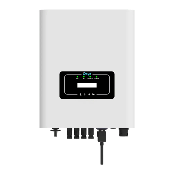
1.1 Appearance Introduc�on Single Phase String Power Inverter can convert solar panel DC power into AC power which can directly input to the grid. Its appearance is shown below.These models contain SUN-7K-G, SUN-7.5K-G, SUN-8K-G, SUN-9K-G, SUN-10K-G and SUN-10.5K-G. The following is collec�vely referred to as “inverter”. - Page 4 1.2 Parts list Please check the following table, to see whether all the parts are included in the package: Moun�ng stainless steel Grid-�ed PV String Inverter Wall moun�ng bracket x1 screws M4×12 DC power connectors Stainless steel an�-collision (including Inserted spring) bolt M6×80 AC power connectors x1 User...
- Page 5 2. Safety warnings and instruc�ons Improper use may result in poten�al electric shock hazards or burns. This manual contains important instruc�ons that should be followed during installa�on and maintenance. Please read these instruc�ons carefully before use and keep them for future reference. 2.1 Safety signs Safety symbols used in this manual, which highlight poten�al safety risks and important safety informa�on, are listed as follows:...
- Page 6 Shock Hazard: When PV module is exposed to sunlight, the output will generate DC voltage. Prohibit touching to avoid shock hazard. Shock Hazard: While disconnect the input and output of the inverter for maintenance, please waits for at least 5 mins un�l the inverter discharge the remnant electricity. High Temperature Hazard: Local temperature of inverter may exceed 80℃...
- Page 7 3. Opera�on Interface 3.1 Interface View Normal Alarm Pic 3.1 Front panel display 3.2 Status Indicator There are four LED status indicator lights in the front panel of the inverter. Please see table 3.1 for details. Indicator status Explanation Inverter detects DC input ●DC off...
- Page 8 3.3 Bu�ons There are four keys in the front panel of the Inverter(from le� to right): Esc, Up, Down and Enter keys. The keypad is used for: ● Scrolling through the displayed op�ons (the Up and Down keys); ● Access to modify the adjustable se�ngs (the Esc and Enter keys). Down Enter 3.4 LCD Display...
- Page 9 4. Product installa�on 4.1 Select installa�on loca�on To select a loca�on for the inverter, the following criteria should be considered: WARNING: Risk of fire ● Do not install the inverter in areas containing highly flammable materials or gases. ● Do not install the inverter in poten�ally explosive atmospheres. ●...
- Page 10 ● Install on a wall or strong structure capable of bearing the weight. ● Install ver�cally with a maximum incline of +/-15°. If the mounted inverter is �lted to an angle greater than the maximum noted, heat dissipa�on can be inhibited, and may result in less than expected output power.
- Page 11 ≥500mm ≥500mm Pic 4.3 Installa�on Gap 4.2 Inverter Installa�on The inverter is designed according to the wall mounted type installa�on, please use the wall mounted (the brick wall of the expansion bolt) when installing. Anchoring Moun�ng bracket Stainless steel screws Inverter Pic 4.4 Inverter Installa�on - 09 -...
- Page 12 Procedure shows below: Locate on the appropriate wall according to the bolt posi�on on the moun�ng bracket, then mark the hole.On the brick wall, the installa�on must be suitable for the expansion bolt installa�on. Pic 4.5 Inverter hanging plate installa�on 2.
- Page 13 5 Electrical Connec�on 5.1 DC input terminal connec�on 1. Switch the Grid Supply Main Switch(AC)OFF. 2. Switch the DC lsolator OFF. 3. Assemble PV input connector to the inverter. Safety Hint: Please don’t connect PV array posi�ve or nega�ve pole to the ground, it could cause serious damages to the inverter.
- Page 14 The steps to assemble the DC connectors are listed as follows: a)Strip off the DC wire about 7mm, disassemble the connector cap nut (see picture 5.3). Pic 5.3 Disassemble the connector cap nut b) Crimping metal terminals with crimping pliers as shown in picture 5.4. Pic 5.4 Crimp the contact pin to the wire c) Insert the contact pin to the top part of the connector and screw up the cap nut to the top part of the connector.
- Page 15 �ons are as shown in Table 5.2. Warning: Prohibit using a single circuit breaker for mul�ple inverters, prohibit the connec�on of load between inverter circuit breakers. Model Cable CSA Cable outer dia Breaker Max cable length SUN-7K-G 10mm 15-18mm 50A/400V SUN-7.5K-G 10mm 15-18mm 50A/400V SUN-8K-G...
- Page 16 The AC output connector is divided into three parts: matching socket, sleeve and sealing- sleeve, as shown in picture 5.7, the steps are as follows: Step 1: Remove the cable sealing ring and sleeve in sequence from the AC connector. Step 2: Separate the sleeve from the matching socket,as shown in picture 5.7, the connector body has two locking holes, and press the locking valve in the hole inward to separate the matching socket from the sleeve.
- Page 17 Step 5: Use the hexagon screwdriver, loosen the bolts of the socket in turn, and insert each cable core into the corresponding jack, and set each screw. The connec�on hole of AC connec�on terminal labeling is shown in picture 5.9. Pic 5.9 AC Connector Hole Pa�ern Step 6: Set the sleeve and sealing ring in place.
- Page 18 5.3 The connec�on of the ground line Good grounding is good for resis�ng surge voltage shock and improving EMI perfor- mance.Therefore, before connec�ng AC, DC and communica�on cables, you need to ground the cable firstly. For a single system, just ground the PE cable. For mul�ple machine systems, all PE cables of the inverter need to be connected to the same grounding copper platoon to ensure the equipoten�al connec�on.
- Page 19 In order to protect the inverter AC connec�on, it is recommended to install a circuit breaker to prevent overcurrent. See table 5.3 below. Rated output Rated output Current for protection Inverter voltage(V) current(A) device(A) SUN-7K-G 30.4 SUN-7.5K-G 32.6 SUN-8K-G 34.8 SUN-9K-G 39.1 SUN-10K-G 43.5...
- Page 20 5.6 Installa�on of datalogger When the inverter is out of the factory, the installa�on loca�on of datalogger is sealed by a plate as shown in Picture 5.13. When installing the datalogger, remove the sealing plate, replace it with the sealing plate with square hole in the accessories, and �ghten the screws. Insert the datalogger into the interface and fix it with a screw.
-
Page 21: Startup And Shutdown
6. Startup and Shutdown Before star�ng the inverter, make sure that the inverter can meet the following condi�ons, otherwise it may result in fire or damage to the inverter. In this case, we do not undertake any responsibility. To op�mize the system configura�on, it is recommended that the two inputs be connected to the same number of PV modules. - Page 22 7. Zero-export func�on (Op�onal) 7.1 Zero-export func�on (Op�on) The string inverter supports zero-export func�on via Energy meter / Limiter(CT) . Based on con�nuously data communica�on, once the Limiter or energy meter detects power export to the grid, it will send the informa�on to the inverter and then inverter will ramp down its ac�ve power according to match the load demand and achieve zero export.
- Page 23 Inverter RS485 limiter DC SWITCH Breaker Solar Panel array VCC_5V 485_B Family load 230V/2T RS 485 meter Female connector RS 485 Male connector 485_A 1+COM 485_A Grid 485_B RS485 Pic 7.2 Connec�on diagram of EASTRON meter Communication Meter SN:2 Pic 7.3 Parameter se�ng EASTRON When the meter connected...
- Page 24 Inverter RS485 limiter DC SWITCH Breaker Solar Panel array VCC_5V 485_B Family load RS 485 Female connector RS 485 Male connector meter 485_A 485_A 485_B Grid Pic 7.4 Connec�on diagram of CHINT meter Meter SN:1 Pic 7.4 Parameter se�ng When the CHNT meter connected successfully, Power: it will shows SN: 1 Warning:...
-
Page 25: Meter Power
7.1.2 Use of zero-export func�on When the connec�on is completed, the following steps should be refered to use this func�on: 1. Turn on the AC switch. 2. Turn on the DC switch, wai�ng for the inverter's LCD is turned on. 3. - Page 26 7.2.1 Zero-export func�on via CT When you are reading this, we believe that you have completed the connec�on according to the requirements of chapter 5, if you has been running your inverter at this �me, and you want to use the limiter func�on, please turn off AC and DC switch of the inverter, and wait for 5 minutes un�l the inverter completely discharged.
- Page 27 7.3 Use of limiter func�on When the connec�on is completed, the following steps should be refered to use this func�on: 1. Turn on the AC switch. 2. Turn on the DC switch, wai�ng for the inverter's LCD is turned on. 3.
- Page 28 7.4 Notes while using zero export func�on For your safety and the opera�on of limiter func�on of the inverter, we put forward the following sugges�ons and precau�ons: Warning: Under zero export mode we strongly recommend that the two PV arrays are formed by the same number of PV panels of the same size, which will make the inverter more responsive to limit the power.
- Page 29 Secondly, go to plant page, if it shows the PV power, load power and grid power, which means the configura�on is correct. - 27 -...
-
Page 30: General Opera�On
8. General Opera�on During normal opera�on, the LCD shows the current status of the inverter, including the current power, total genera�on, a bar chart of power opera�on and inverter ID, etc. Press the Up key and the Down key to see the current DC voltage, DC current, AC voltage, AC current, inverter radiator temperature, so�ware version number and Wifi... - Page 31 8.1 The ini�al interface From the ini�al interface, you can check PV power, PV voltage, grid voltage, inverter ID, model and other infoma�on. Power: Power: State: Standby State: Com.Error Pic 8.2 The ini�al interface Press UP or Down, you can check inverter DC voltage, DC current, AC voltage, AC current and inverter temperature.
- Page 32 Load Power: Pic 8.10 Load power LoadEp: Daily consump�on; LoadEp: 0.00KWh Total: Total energy consump�on. Total : 0.00KWh Pic 8.11 Load consump�on E-Day: Daily genera�on; E-Day : E-Total: Total genera�on. E-Total : 134KWh Pic 8.12 PV genera�on 8.2 Submenus in the Main Menu There are five submenus in the Main Menu.
- Page 33 8.2.2 Fault Record It can keep four fault records in the menu including �me, customer can deal with it depends on the error code. Device Info. 1 F35 200521 15 Fault Record << 2 F56 200519 17 Pic 8.14 Fault Record 8.2.3 ON/OFF se�ng ON / OFF <<...
- Page 34 8.2.5 Parameter se�ng There are five submenus in the setup.Se�ng includes system param, run param, protect param, comm: param. All of these informa�on for maintenance reference. Setup << System Param << PV VA Param Protect Param Comm. Param << Pic 8.17 Submenus of the parameter setup 8.3 System param se�ng System Param includes �me set, language set, display set and factory reset.
- Page 35 8.4 Running param set Note: Password required-- only for access-authorized engineer. Un-authorized access may avoid the warranty. The ini�al password is 1234. PassWord Pic 8.24Password 8.4.1 Ac�veP set Adjust the output ac�ve power in % ActiveP Reac�veP: Adjust reac�ve power output in % ReactiveP 0% <<...
- Page 36 Limiter: If inverter will connect SUN limiter, Meter_ct then set here to ON Limiter ON << Pic 8.29 Feed_In %: it is used to deploy how much Feed-in 50% << power can be feed into grid. For example, Feed_in=50% of the 10.5KW model, MPPT Num 0 <<...
- Page 37 OFDMode HYS OFDMode HYS <- OFDPoint 0.00 << OFDPoint 0.00 OFDerate 0.0% << Pic 8.31 ac�ve power droop LimExMode: There're two kinds of zero-export modes Meter for the syetem when connec�ng meter LimExMode AVG << AVG: According to the average power of three phase Meter MIN:...
- Page 38 Hysteresis mode for ac�ve power droop OFDMode HYS <- OFDMode HYS the start frequency at which ac�ve power droop is taken to act OFDPoint 0.00 << OFDPoint 0.00 The slope of the ac�ve power reduc�on OFDerate 0.0% << 8.5 Protect Param Note: Engineer Only.
- Page 39 Note: Engineer only. AC OverVoltage << AC LowVoltage << U1: 260.0V U1: 195.5V Tripping Time1 << Tripping Time1 << Time1: 2000ms Time1: 2000ms AC OverVoltage << AC LowVoltage << U2: 265.0V U2: 185.0V Tripping Time2 << Tripping Time2 << Time2: 500ms Time2: 500ms AC OverVoltage <<...
- Page 40 Tripping Time1 << Tripping Time1 << Time1: 2000ms Time1: 2000ms AC OverFreq << AC LowFreq << 2 : 53.00Hz 2 : 47.00Hz Tripping Time2 << Tripping Time2 << Time2: 500ms Time2: 500ms AC OverFreq << AC LowFreq << 3 : 54.00Hz 3 : 46.00Hz Tripping Time3 <<...
-
Page 41: Repair And Maintenance
Check the solar panel output connec�on. Failure in reading memory (EEPROM). Restart the inverter if the Read the memory error fault s�ll exists, contact your installer or Deye service. Failure in wri�ng memory (EEPROM). Restart the inverter if the Write the memory error fault s�ll exists, contact your installer or Deye service. - Page 42 AC over current fault of hardware 2. Restart the inverter or factory reset, if the error s�ll exists, please contact your installer or Deye service. 1. When inverter is running, wifi plug plugin,will occur F19. All hardware failure synthesis 2.
- Page 43 3. Check if the so�ware is not suitable for this inverter. (Old AC main contactor failure inverter not have relays detec�on func�on) 4. restart the inverter, if the fault s�ll exists, contact your installer or Deye service. Dc boost so� start Not avaiable. Inverter 2 dc high fault Hardly appear the code.
- Page 44 DC busbar voltage is too low then showing F56, maybe Loss of driver or need update firmware. 3. Restart the inverter, if the fault s�ll exists, contact your installer or Deye service. AC reverse irriga�on AC reverse irriga�on. AC grid U over current Hardly appear the code.
- Page 45 11.Specifica�on Model SUN-7K-G SUN-7.5K-G SUN-8K-G SUN-8K-G Input Side Max.DC Power(kW) 10.4 10.4 Max.DC Input Voltage(V) Start-up DC Input Voltage(V) MPPT Opera�ng Range(V) 70~500 Max.DC Input Current(A) 13+26 Max. Short Circuit Current (A) 19.5+39 Number of MPPT/Strings per MPPT 2/1+2 Output Side Rated Output Power(kW) Max.Ac�ve Power(kW)
- Page 46 Model SUN-9K-G SUN-10K-G SUN-10.5K-G Input Side Max.DC Power(kW) 11.7 13.7 Max.DC Input Voltage(V) Start-up DC Input Voltage(V) MPPT Opera�ng Range(V) 70~500 Max.DC Input Current(A) 26+26 Max. Short Circuit Current (A) 39+39 Number of MPPT/Strings per MPPT 2/2+2 Output Side 10.5 Rated Output Power(kW) 10.5 Max.Ac�ve Power(kW)
- Page 47 Add: No.26-30, South Yongjiang Road, Beilun, 315806, Ningbo, China Tel: +86 (0) 574 8622 8957 Fax: +86 (0) 574 8622 8852 E-mail: service@deye.com.cn Web: www.deyeinverter.com 30240301000636 Ver: 2.1, 2021-12-20...
Need help?
Do you have a question about the SUN-7K-G and is the answer not in the manual?
Questions and answers