
Related Manuals for Deye SUN-3K-G03-1


Summary of Contents for Deye SUN-3K-G03-1
- Page 1 Grid-connected PV Inverter SUN-3K-G03 SUN-3K-G03-1 SUN-4K-G03 SUN-5K-G03 SUN-6K-G03 SUN-7K-G03 SUN-8K-G03 SUN-10K-G03 SUN-12K-G03 User Manual...
- Page 2 1. Introduction - 02 - ………………………………………………………… 1.1 Appearance Introduction - 02 - ………………………………………… 1.2 Parts list - 03 - ………………………………………………………… 2. Safety warnings and instructions - 04 - ……………………………………… 2.1 Safety signs - 04 - ………………………………………………………… 2.2 Safety instructions - 04 - …………………………………………………...
- Page 3 Documents must be stored carefully and be available at all �mes. Contents may be periodically updated or revised due to product development. The informa�on in this manual is subject to change without no�ce. The latest manual can be acquired via service@deye.com.cn Photovoltaic Grid-connected System...
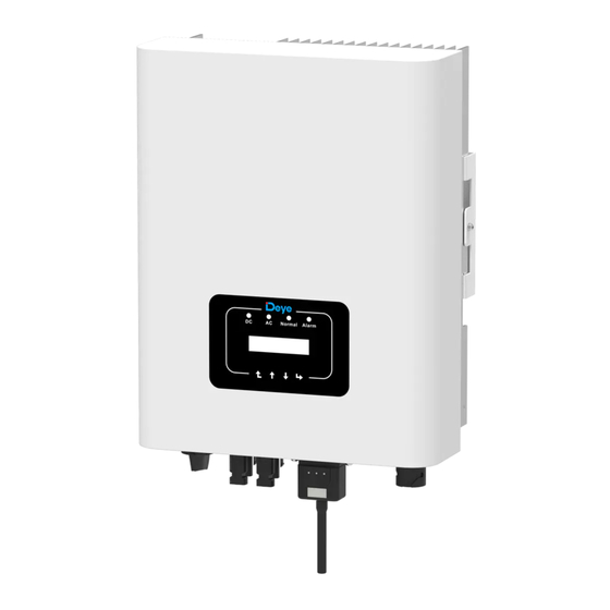
- Page 4 1.1 Appearance Introduc�on On-grid Inverter can convert solar panel DC power into AC power which can directly input to the grid. Its appearance is shown below.These models contain SUN-3K-G03, SUN-3K-G03-1,SUN-4K-G03, SUN-5K-G03, SUN-6K-G03, SUN-7K-G03, SUN-8K-G03,SUN-10K-G03, SUN-12K-G03. The following is collec�vely referred to as “inverter”.
- Page 5 1.2 Parts list Please check the following table, to see whether all the parts are included in the package: Moun�ng stainless steel Grid-�ed PV String Inverter Wall moun�ng bracket x1 screws M4×12 DC power connectors Stainless steel an�-collision AC power connectors x1 (including Inserted spring) bolt M6×80 User...
- Page 6 2. Safety warnings and instruc�ons Improper use may result in poten�al electric shock hazards or burns.This manual contains important instruc�ons that should be followed during installa�on and maintenance. Please read these instruc�ons carefully before use and keep them for future reference. 2.1 Safety signs Safety symbols used in this manual, which highlight poten�al safety risks and important safety informa�on, are listed as follows:...
- Page 7 Shock Hazard: When PV module is exposed to sunlight, the output will generate DC voltage. Prohibit touching to avoid shock hazard. Shock Hazard: While disconnect the input and output of the inverter for maintenance, please waits for at least 5 mins un�l the inverter discharge the remnant electricity. High Temperature Hazard: Local temperature of inverter may exceed 80℃...
- Page 8 3. Opera�on Interface 3.1 Interface View Normal Alarm Pic 3.1 Front panel display 3.2 Status Indicator There are four LED status indicator lights in the front panel of the inverter. Please see table 3.1 for details. Indicator status Explanation Inverter detects DC input ●DC off...
- Page 9 3.3 Bu�ons There are four keys in the front panel of the Inverter(from le� to right): Esc, Up, Down and Enter keys. The keypad is used for: ● Scrolling through the displayed op�ons (the Up and Down keys); ● Access to modify the adjustable se�ngs (the Esc and Enter keys). Down Enter 3.4 LCD Display...
- Page 10 4. Product installa�on 4.1 Select installa�on loca�on To select a loca�on for the inverter, the following criteria should be considered: WARNING: Risk of fire ● Do not install the inverter in areas containing highly flammable materials or gases. ● Do not install the inverter in poten�ally explosive atmospheres. ●...
- Page 11 ● Install on a wall or strong structure capable of bearing the weight. ● Install ver�cally with a maximum incline of +/-15°. If the mounted inverter is �lted to an angle greater than the maximum noted, heat dissipa�on can be inhibited, and may result in less than expected output power.
- Page 12 ≥500mm ≥500m Pic 4.3 Installa�on Gap 4.2 Inverter Installa�on The inverter is designed according to the wall mounted type installa�on, please use the wall mounted (the brick wall of the expansion bolt) when installing. Anchoring Moun�ng bracket Stainless steel screws Inverter Pic 4.4 Inverter Installa�on - 10 -...
- Page 13 Procedure shows below: 1. Locate on the appropriate wall according to the bolt posi�on on the moun�ng bracket, then mark the hole.On the brick wall, the installa�on must be suitable for the expansion bolt installa�on. Pic 4.5 Inverter hanging plate installa�on 2.
- Page 14 5 Electrical Connec�on 5.1 DC input terminal connec�on 1. Switch the Grid Supply Main Switch(AC)OFF. 2. Switch the DC lsolator OFF. 3. Assemble PV input connector to the inverter. Safety Hint: Please don’t connect PV array posi�ve or nega�ve pole to the ground, it could cause serious damages to the inverter.
- Page 15 The steps to assemble the DC connectors are listed as follows: a) Strip off the DC wire about 7mm, disassemble the connector cap nut (see picture 5.3). Pic 5.3 Disassemble the connector cap nut b) Crimping metal terminals with crimping pliers as shown in picture 5.4. Pic 5.4 Crimp the contact pin to the wire c) Insert the contact pin to the top part of the connector and screw up the cap nut to the top part of the connector.
- Page 16 Prohibit using a single circuit breaker for mul�ple inverters, prohibit the connec�on of load between inverter circuit breakers. Model Cable CSA Cable outer dia Breaker Max cable length SUN-3K//4K/5K Outside cable 15-18mm 20A/400V /6K/7K/8K/10K-G03 (3+N+PE)20m SUN-3K-G03-1 Outside cable SUN-12K-G03 20-25mm 30A/400V (3+N+PE)20m Table 5.2 Cable informa�on - 14 -...
- Page 17 The AC output connector is divided into three parts: matching socket, sleeve and sealing- sleeve, as shown in picture 5.7, the steps are as follows: Step 1: Remove the cable sealing ring and sleeve in sequence from the AC connector. Step 2: Use strippers to strip the protec�ve sheath and insula�on layer of the AC cable to the right length, as shown in Picture 5.8.
- Page 18 Pic 5.9 AC Connector Hole Pa�ern Step 5: Set the sleeve and sealing ring in place. Step 6: Connect the terminals to the inverter as shown in picture 5.10. Pic 5.10 AC input connec�on - 16 -...
- Page 19 5.3 The connec�on of the ground line Good grounding is good for resis�ng surge voltage shock and improving EMI perfor- mance.Therefore, before connec�ng AC, DC and communica�on cables, you need to ground the cable firstly. For a single system, just ground the PE cable. For mul�ple machine systems, all PE cables of the inverter need to be connected to the same grounding copper platoon to ensure the equipoten�al connec�on.
- Page 20 In order to protect the inverter AC connec�on, it is recommended to install a circuit breaker to prevent overcurrent. See table 5.3 below. Rated output Rated output Current for protection Inverter voltage(V) current(A) device(A) SUN-3K-G03 SUN-3K-G03-1 SUN-4K-G03 SUN-5K-G03 SUN-6K-G03 SUN-7K-G03 10.1 SUN-8K-G03 11.6 SUN-10K-G03 14.5 SUN-12K-G03 17.4...
- Page 21 5.6 Installa�on of datalogger When the inverter is out of the factory, the installa�on loca�on of datalogger is sealed by a sealed plate as shown in Picture 5.13. When installing the datalogger, remove the sealing plate, replace it with the sealing plate with square hole in the accessories, and �ghten the screws. Insert the datalogger into the interface and fix it with a screw.
- Page 22 6. Startup and Shutdown Before star�ng the inverter, make sure that the inverter can meet the following condi�ons, otherwise it may result in fire or damage to the inverter. In this case, we do not undertake any responsibility. At the same �me, to op�mize the system configura�on, it is recommended that the two inputs be connected to the same number of photovoltaic modules.
- Page 23 7 Zero export func�on via SUN limiter The inverter has external zero export func�on. This func�on is op�onal. It can collect counter- current power to control the output power of the inverter, so that the power of inverter and load can be offset, and the excess power will not be fed back to the grid. If you purchase the inverter with zero export func�on, an external zero export device ( SUN limiter or energy meter) will be included in the package which is necessary for the func�on.The SUN limiter shows as Pic 7.1.You can see corresponding line mark next to the green interface.
- Page 24 We recommend installing an AC switch between the inverter outlet and the u�lity grid, the specs of the AC switchis determined by the load capacity. The AC switch we recommend to connect to the inverter output refer to Table 5.2. L1(L) Solar panels L1(K)
- Page 25 Load Pic 7.3 Clamp Senor Pic 7.4 Clamp Senor internal arrow (3) A�er you finish the installa�on in process 1 and 2, connect the N line (N) to the N terminal of the limiter and �ghten the line. (4) Connect the control line. There are two numbers 1 and 2 on the interface of SUN limiter, and the same on the waterproof terminal of the inverter.
- Page 26 Pic 7.7 Connect terminal to inverter 7.3 Use of zero export func�on When the connec�on is completed, the following steps should be referenced to use this func�on: 1. Turn on the AC switch 2. Turn on the DC switch, Wai�ng inverter LCD ligh�ng up 3.
- Page 27 *Fun GFDI OFF Utility Power: Limiter ON << * This item is not avaiable for some FW verison Pic 7.10 Limiter func�on turn on 7. [u�lity power] showing posi�ve means grid power is consuming energy, and there is no backflow. If [u�lity power] shows nega�ve, which means there’s excess PV energy flows to grid or current transformer arrow direc�on is in wrong direc�on.
- Page 28 1 2 3 4 5 6 7 8 Eastron (1,2,3,4) (5,6,7,8) B A G RS 485 RS 485 B RS 485 A Pic 7.11 Eastron meter Eastron SDM630-Modbus V2 Inverter Solar Panel array SUN-12K-G03 SUN-(3-10)K-G03 AC Breaker RS 485 Male connector Family load VCC_5V...
- Page 29 9 1 0 11 1 2 1 3 1 4 1 5 1 6 1 7 1 8 1 9 2 0 Eastron 1 2 3 4 15 16 17 18 19 20 Grid voltage Auxiliary Current inputs sampling power supply 1 4 1 3 1 2 RS 485 RS 485 A RS 485 B...
- Page 30 Three-Phase Smart Meter (1,4,7,10) (3,6,9,10) RS 485 Pic 7.14 CHINT meter CHINT DTSU666 Inverter Solar Panel array SUN-12K-G03 SUN-(3-10)K-G03 AC Breaker RS 485 Male connector Family load L1 L2 L3 N VCC_5V 485_B RS 485 Female connector Three-Phase Smart Meter meter 485_A L1 L2 L3 N...
- Page 31 7.4.2 Use of zero-export func�on When the connec�on is completed, the following steps should be refered to use this func�on: 1. Turn on the AC switch. 2. Turn on the DC switch, wai�ng for the inverter's LCD is turned on. 3.
- Page 32 7.5 Notes while using zero export func�on For your safety and the opera�on of limiter func�on of the inverter, we put forward the following sugges�ons and precau�ons: Warning: Under zero export mode we strongly recommend that the two PV arrays are formed by the same number of PV panels of the same size, which will make the inverter more responsive to limit the power.
- Page 33 And then choose your system type as “Self-consump�on” Secondly, go to plant page, if it shows the PV power, load power and grid power, which means the configura�on is correct. - 31 -...
- Page 34 8. General Opera�on During normal opera�on, the LCD shows the current status of the inverter, including the current power, total genera�on, a bar chart of power opera�on and inverter ID,etc. Press the Up key and the Down key to see the current DC voltage, DC current, AC voltage, AC current,in- verter radiator temperature,so�ware version number and Wifi...
- Page 35 Power: Power: State: Standby State: Com.Error Pic 8.2 The ini�al interface Press UP or Down, you can check inverter DC voltage, DC current, AC voltage, AC current and inverter temperature. Total DC Power: PV1: 0.0V 0.0A Power: Pic 8.3 Total input power Pic 8.4 PV input voltage and current informa�on UA: 234V 0.0A...
- Page 36 ExpEp: Daily energy sold to grid; *ExpEp: 0.00KWh Total: Total energy sold to grid. *Total : 0.00KWh Pic 8.11 Electrical energy *Load Power: Pic 8.12 Load power LoadEp: Daily consump�on; *LoadEp: 0.00KWh Total: Total energy consump�on. *Total: 0.00KWh Pic 8.13 Load consump�on 8.2 Submenus in the Main Menu There are five submenus in the Main Menu.
- Page 37 8.2.2 Fault Record It can keep Eight fault records in the menu including �me, customer can deal with it depends on the error code. Device Info. 1 F35 200521 15 Fault Record << 2 F56 200519 17 Pic 8.15 Fault Record 8.2.3 ON/OFF se�ng ON / OFF <<...
- Page 38 8.3 System param se�ng System Param includes �me set, language set, display set and factory reset. Time Set << Display Set Language Set Factory Reset << Pic 8.18 System Param 20200522 OK English << Angielski 08:11:21 Cancel Pic 8.19 Time Pic 8.20 Language Bright Keep <<...
- Page 39 8.4.1 Ac�veP set Adjust the output ac�ve power in % ActiveP Reac�veP: Adjust reac�ve power output in % ReactiveP 0% << Pic 8.25 Fun_ISO: Insula�on resistance detec�on 1.000 Fun ISO OFF << Pic 8.26 Fun_RCD: Residual current detec�on Fun RCD Self-check: Inverter's self-check �me.The default value 60s SelfCheck...
- Page 40 Meter Meter LimExMode MIN <- LimExMode AVG << Pic 8.30.1 op�onal meter mode WindTurbine WindTurbine OFF <- ON <- WindTurbine CLR <- Pic 8.30.2 Arc-Fault Detec�on OFDMode OFF <- OFDMode ON <- OFDMode HYS OFDMode HYS <- OFDPoint 0.00 << OFDPoint 0.00 OFDerate 0.0% <<...
- Page 41 LimExMode: There're two kinds of zero-export modes Meter for the syetem when connec�ng meter LimExMode AVG << AVG: According to the average power of three phase Meter MIN: According the minimum power among three phase LimExMode MIN <- WindTurbine Clear arc fault manually CLR <- WindTurbine Arc-fault detec�on func�on enable/disable...
- Page 42 8.5 Protect Param Note: Engineer Only. We will set the param depends on the safety requirements, so customers don't need to reset it. The password is same as 8.4 Running param PassWord Pic 8.31 Password 00 INMETRO 00 EN50438 00 EN50549 <<...
- Page 43 AC OverVoltage << AC LowVoltage << U2: 265.0V U2: 185.0V Tripping Time2 << Tripping Time2 << Time2: 500ms Time2: 500ms AC OverVoltage << AC LowVoltage << U3: 270.0V U3: 160.0V Tripping Time3 << Tripping Time3 << Time3: 200ms Time3: 200ms AC OverFreq <<...
- Page 44 Tripping Time3 << Tripping Time3 << Time3: 200ms Time3: 200ms Rated Voltage << << 127/220V Cancel Pic 8.32 “CUSTOMIZED” Please set the proper grid parameters according to the requirements of your current country's grid regula�ons.If you are not clear about it, please consult your installer. 8.6 Comm.
- Page 45 Check the solar panel output connec�on. Failure in reading memory (EEPROM). Restart the inverter if the Read the memory error fault s�ll exists, contact your installer or Deye service. Failure in wri�ng memory (EEPROM). Restart the inverter if the Write the memory error fault s�ll exists, contact your installer or Deye service.
- Page 46 3. Check if the inverter FW version is suitable for the hardware. 4. Restart the inverter, if the error s�ll exists, please contact your installer or Deye service. DC leakage flow fault Hardly appear the code. Never ever happened so far.
- Page 47 1. Check AC current sensor and its circuit. AC over current(one cycle) 2. Restart the inverter, if the fault s�ll exists, contact your installer or Deye service. DC over current Hardly appear the code. Never ever happened so far. Check the AC voltage protec�on se�ng. And Check if the AC AC Line W,U over voltage cable is too thin.Check the voltage difference between LCD and...
- Page 48 DC busbar voltage is too low then showing F56, maybe Loss of driver or need update firmware. 3. Restart the inverter, if the fault s�ll exists, contact your installer or Deye service. AC reverse irriga�on AC reverse irriga�on. AC grid U over current Hardly appear the code.
- Page 49 11.Specifica�on SUN-3K- SUN-3K- SUN-4K- SUN-5K- SUN-6K- Model G03-1 Input Side Max.DC Power(kW) Max.DC Input Voltage(V) 1000 Start-up DC Input Voltage(V) MPPT Opera�ng Range(V) 120~850 13+13 Max.DC Input Current(A) Max. Short Circuit Current (A) 19.5+19.5 Number of MPPT/Strings per MPPT 2/1+1 Output Side Rated Output Power(kW) Max.Ac�ve Power(kW)
- Page 50 Model SUN-7K-G03 SUN-8K-G03 SUN-10K-G03 SUN-12K-G03 Input Side Max.DC Power(kW) 10.4 15.6 Max.DC Input Voltage(V) 1000 Start-up DC Input Voltage(V) 250V MPPT Opera�ng Range(V) 120~850 200~850 Max.DC Input Current(A) 13+13 Max. Short Circuit Current (A) 19.5+19.5 Number of MPPT/Strings per MPPT 2/1+1 Output Side Rated Output Power(kW)
- Page 51 Add: No.26-30, South Yongjiang Road, Beilun, 315806, Ningbo, China Tel: +86 (0) 574 8622 8957 Fax: +86 (0) 574 8622 8852 E-mail: service@deye.com.cn Web: www.deyeinverter.com - 20 - 30240301000403 Ver: 2.1, 2022-3-01...
Need help?
Do you have a question about the SUN-3K-G03-1 and is the answer not in the manual?
Questions and answers