Deye SUN-80K-G User Manual
Grid-tied pv string inverter
Hide thumbs
Also See for SUN-80K-G:
- User manual (53 pages) ,
- User manual (54 pages) ,
- User manual (67 pages)

Related Manuals for Deye SUN-80K-G


Summary of Contents for Deye SUN-80K-G
- Page 1 Grid-tied PV String Inverter SUN-60K-G SUN-70K-G SUN-75K-G SUN-80K-G User Manual...
- Page 2 - 1 - 1. Introduction ………………………………………………………… - 1 - 1.1 Appearance introduction …………………………………………… - 2 - 1.2 Parts list ………………………………………………………… - 3 - 2. Safety warnings and instructions ………………………………………… - 3 - 2.1 Safety signs ……………………………………………………… - 3 - 2.2 Safety Guide ………………………………………………………...
-
Page 3: Introduc�On
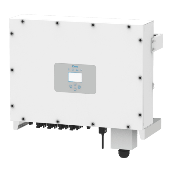
On-grid inverter can convert solar panel DC power into AC power which can directly input to the grid. Its appearance is shown below. These models contain SUN-60K-G, SUN-70K-G, SUN-75K-G, SUN-80K-G. The following is collec�vely referred to as “inverter”. Pic 1.1 Front view Pic 1.2 Bo�om view... - Page 4 1.2 Parts list Please check the following table, to see whether all the parts are included in the package: Moun�ng stainless steel Grid-�ed PV String Inverter Wall moun�ng bracket x 1 screws M4×12 x 10 DC power connectors Stainless steel an�-collision (including Inserted spring) Wrench x 1 bolt M6×80...
- Page 5 2. Safety warnings and instruc�ons Improper use may result in poten�al electric shock hazards or burns. This manual contains important instruc�ons that should be followed during installa�on and maintenance. Please read these instruc�ons carefully before use and keep them for future reference. 2.1 Safety Symbols Safety symbols used in this manual, which highlight poten�al safety risks and important safety informa�on, are listed as follows:...
- Page 6 Shock Hazard: When PV module is exposed to sunlight, the output will generate DC voltage. Prohibit touching to avoid shock hazard. Shock Hazard: While disconnect the input and output of the inverter for maintenance, please waits for at least 5 mins un�l the inverter discharge the remnant electricity. High Temperature Hazard: Local temperature of inverter may exceed 80℃...
- Page 7 3. Opera�on Interface 3.1 Interface View Pic 3.1 Front panel display 3.2 Status Indicator The inverter panel has 4 indicators, the le� one is dc output indicators, green indicates normal DC input. Beside is the AC indicator, green indica�ng normal ac connec�on. Beside the AC indicator is the opera�ng indicator, green indica�ng normal output.
- Page 8 3.3 Bu�ons There are four bu�ons on the inverter panel:Above is Up and increase bu�on(UP), Below is down and decrease bu�on(DOWN), Le� is ESC bu�on(ESC), Right is Enter bu�on(ENTER). Achieving below func�ons by the four bu�ons: ● Page turning (use UP and DOWN bu�on) ●...
- Page 9 flow of air around the inverter is not blocked. ● Exposure to direct sunlight will increase the opera�onal temperature of the inverter and may cause output power limi�ng. Deye recommends inverter installed to avoid direct sunlight or raining.
- Page 10 ● Install on a wall or strong structure capable of bearing the weight. ● Install ver�cally with a maximum incline of +/-15°. If the mounted inverter is �lted to an angle greater than the maximum noted, heat dissipa�on can be inhibited, and may result in less than expected output power.
- Page 11 ≥500mm ≥500mm Pic 4.3 Installa�on Gap 4.2 Inverter of inverter Pic 4.4 Mou�ng bracket dimensions - 09 -...
- Page 12 4.3 Inverter Installa�on The inverter should be mounted in a ver�cal posi�on. The steps of moun�ng are as follows 1. For brick walls, the posi�on of the holes should be suitable for the expansion bolts. 2. Make sure the bracket is horizontal and the moun�ng holes are in the correct points. Drilling the holes on the wall according the marks.
- Page 13 5 Electrical Connec�on 5.1 DC input terminal connec�on 1. Switch the Grid Supply Main Switch(AC)OFF. 2. Switch the DC lsolator OFF. 3. Assemble PV input connector to the inverter. Safety Hint: Please don’t connect PV array posi�ve or nega�ve pole to the ground, it could cause serious damages to the inverter.
- Page 14 The steps to assemble the DC connectors are listed as follows: a) Strip off the DC wire about 7mm, disassemble the connector cap nut (see picture 5.3). Pic 5.3 Disassemble the connector cap nut b) Crimping metal terminals with crimping pliers as shown in picture 5.4. Pic 5.4 Crimp the contact pin to the wire c) insert the contact pin to the top part of the connector and screw up the cap nut to the top part of the connector.
- Page 15 d) Finally insert the DC connector into the posi�ve and nega�ve input of the inverter, shown as picture 5.6 Pic 5.6 DC input connec�on Warning: Sunlight shines on the panel will generate voltage, high voltage in series may cause danger to life. Therefore, before connec�ng the DC input line, the solar panel needs to be blocked by the opaque material and the DC switch should be 'OFF', otherwise, the high voltage of the inverter may lead to life- threatening condi�ons.
- Page 16 AC wire produc�on method is the same as that of 5.2.1. AC wire installa�on method: 1) Remove the 8 fixing screws on the AC junc�on box of the inverter as shown in Pic 5.7. A�er removing the junc�on box, you can see the terminals of the inverter. The default is 5 digits as shown in Pic 5.8.
- Page 17 Pic 5.11 Pic 5.11 Tighten the AC junc�on box 5.2.3 Recommended current protector specifica�ons Inverter Rated voltage Rated output power(KW) Current protection device(A) SUN-60K-G SUN-70K-G SUN-75K-G SUN-80K-G Table 5.3 Recommended current protector specifica�ons - 15 -...
- Page 18 5.3 Connec�on of the ground line Good grounded is important for resist the surge voltage shock and improve EMI's performance. So before the connec�on of AC, DC, communica�on connec�ons, inverter needs to ground first. For a single system, just ground the PE cable; For mul�ple machine systems, all PE cables of the inverter need to be connected to the same grounding copper platoon to ensure the equipotent connec�on.
- Page 19 Phone GPRS Router Web Server WIFI Pic 5.13 Internet monitoring solu�on 5.4.1 Installa�on of datalogger When the inverter is out of the factory, the loca�on of the installa�on of datalogger is sealed by a sealed plate as shown in Picture 5.14. When installing the datalogger, remove the sealing plate, replace it with the sealing plate with square hole in the accessories, and �ghten the screws.
-
Page 20: Start Up And Shut Off
5.4.2 Configura�on of datalogger datalogger datalogger For the configura�on of , please refer to illustra�ons of the 6. Start up and Shut off Ensure that the inverter meets the following condi�ons before star�ng the inverter, otherwise it may cause fire or damage to the inverter without quality assurance, at the same �me the situa�on on our company does not undertake any responsibility. - Page 21 7 Zero export func�on via SUN limiter The inverter has external zero export func�on. This func�on is op�onal. It can collect counter- current power to control the output power of the inverter, so that the power of inverter and load can be offset, and the excess power will not be fed back to the grid. If you purchase the inverter with zero export func�on, an external zero export device ( SUN limiter or energy meter) will be included in the package which is necessary for the func�on.
- Page 22 We recommend installing an AC switch between the inverter outlet and the u�lity grid, the specs of the AC switchis determined by the load capacity. The AC switch we recommend to connect to the inverter output refer to Table 5.2. L1(L) L1(K) Solar panels...
- Page 23 Pic 7.3 Clamp Sensor Pic 7.4 Clamp Sensor internal arrow (3) A�er you finish the installa�on in process 1 and 2, connect the N line (N) to the N terminal of the limiter and �ghten the line. (4) Connect the control line. There are two numbers 1 and 2 on the interface of SUN limiter, and the same on the waterproof terminal of the inverter.
- Page 24 Pic 7.5 Waterproof terminal limiter Pic 7.6 Connect SUN limiter to inverter Pic 7.7 Connect terminal to inverter - 22 -...
- Page 25 7.3 Debugging SUN Limiter Turn on the an�-backflow func�on of the inverter refer to the manual , then turn on the SUN limiter's power supply, next close the DC switch, and last turn on the inverter. MENU》Setup》Run Param ActiveP Island ReactiveP 0.0% Meter -1.000...
- Page 26 7.4 Zero-export func�on (Op�on) The string inverter supports zero-export func�on via Energy meter / SUN-Limiter. Based on con�nuously data communica�on, once the Limiter or energy meter detects power export to the grid, it will send the informa�on to the inverter and then inverter can instruct the inverter to ramp down its ac�ve power according to match the load demand and achieve zero export.
- Page 27 Grid Inverter Solar Panel array meter RS485 Communication VCC_5V 485_A 485_B Family load Pic 7.10 Connec�on diagram of CHINT meter Warning: Ensuring grid input cables connect 1/4/7/10 port of energy meter, and inverter AC output cables connect 3/6/9/10 port of energy meter when connec�ng. 7.4.2 Debugging energy meter Turn on the an�-backflow func�on of the inverter refer to the manual, next close the DC switch, and last turn on the inverter.
-
Page 28: General Opera�On
8. General Opera�on During normal opera�on, the LCD shows the current status of the inverter, including the current power, total genera�on, a bar chart of power opera�on and inverter ID, etc. Press the Up key and the Down key to see the current DC voltage, DC current, AC voltage, AC current, inverter radiator temperature, so�ware version number and Wifi... - Page 29 8.1 The ini�al interface From the ini�al interface, you can check power, day power, total power, invertert ID , model and �me. 0.0Kw SN-01 2019-05-11 08:00:00 29.86Kw P - 45 Kw Power: 295kWh Day : 25 MWh Total : State : Standby ID:1601012001 Pic 8.1 The ini�al interface...
- Page 30 Grid Ua : 234.5V Ia : 0.0A Grid Freq : 50.00Hz Pic 8.3 AC running state informa�on You can check the three phase voltage, current, and grid frequency. Ver : 0166 Ver : 1860 Pic 8.4 Inverter firmware version You can check the inverter LCD so�ware Ver0166 and Control So�ware Version Ver1860. There are two black spot in the bo�om right corner.
- Page 31 8.1.1 Main Menu There are four submenu in the Main Menu. MENU Statistics 《 Fault Record ON/OFF Setup PV VA Pic 8.5 Main Menu 8.2 Sta�s�cs informa�on There are five submenu in the sta�s�cs. MENU》Statistics E-Day E-History E-Month Test Data 《...
- Page 32 MENU》Statistics》E-Day <2019-05-11> 10MWh Pic 8.7 E-Day MENU》Statistics》E-Month 2019-04 1-10 20 31 <> 10MWh Pic 8.8 E-Month MENU》Statistics》E-Year <2019> 200KWh Pic 8.9 E-Year - 30 -...
- Page 33 MENU》Statistics》E-History <2015-2024> 5KWh Pic 8.10 E-History This informa�on is for technician’s reference. 19186 11126 2057 19198 11140 137 : 2145 19152 16666 2248 9119 2927 1497 24362 12218 2065 2653 Pic 8.11Test Data 8.3 Fault Record Only can keep four fault record in the menu include �me, customer can deal with it depends on the error code.
- Page 34 MENU》Fault Record Fault F352019-05-05 08:38 History : F352019-05-05 08:37 F352019-04-24 18:47 F352019-04-24 17:54 F352019-04-24 17:53 Pic 8.12 Fault Record 8.4 ON/OFF se�ng MENU》ON/OFF Turn ON Turn OFF 《 Pic 8.13 ON/OFF se�ng Into each submenu through cursor. - 32 -...
- Page 35 MENU》ON/OFF》Turn ON 《 Turn ON Cancel Pic 8.14 ON set MENU》ON/OFF》Turn OFF 《 Turn OFF Cancel Pic 8.15 OFF set 8.5 Parameter se�ng Se�ng includes system param, run param, protect param, comm.. param. All of these informa�on for maintenance reference. - 33 -...
-
Page 36: Menu Setup
MENU》Setup System Param 《 Param Protect Param Comm. Param Pic 8.16 Se�ng 8.5.1 System Param System Param includes �me set, language set, display set and factory date reset. MENU》Setup》System Param Time Set 《 Language Set Display Set Factory data reset Pic 8.17 System Param 8.5.1.2 Time Set Time Set... - Page 37 8.5.1.3 Language Set Lauguage Set 简体中文 English 《 Angielski Pic 8.19 Lauguage set 8.5.1.4 Display Set Display Set Brightness Delay 《 Delay time 05S Cancel Pic 8.20 Display set 8.5.1.5 Factory data reset Factory data reset Confirm to reset 《 Cancel Pic 8.21 Factory data reset set - 35 -...
- Page 38 8.5.2 Running Param Note: Password required-- only for access-authorized engineer. Un-authorized access may avoid the warranty. The ini�al password is 1234. PassWord * * * * Pic 8.22 Password MENU》Setup》Run Param ActiveP Island ReactiveP 0.0% Meter -1.000 Limiter Fun_ISO OFF E_Coef 0.00 Fun_RCD OFF...
- Page 39 MENU》Setup》Protect Param INMETRO 《 EN50949 EN50438 IEC61727 CUSTOM Cancel Pic 8.24 Protect Param Note: Engineer only. CUSTOM AC OverVoltage 240.0V 《 AC LowVoltage 235.0V AC OverFreq 52.00Hz AC LowFrwq 48.00Hz Rated Voltage 127/220V Cancel Pic 8.25 “CUSTOM” 8.5.4 Comm. Param MENU》Setup》Comm.Param Address : 01 《...
-
Page 40: Repair And Maintenance
9. Repair and Maintenance String type inverter doesn’t need regular maintenance. However,debris or dust will affect heat sink’s thermal performance. It is be�er to clean it with a so� brush. If the surface is too dirty and affect the reading of LCD and LED lamp, you can use wet cloth to clean it up. Warning: When the device is running, the local temperature is too high and the touch can cause burns. - Page 41 Error code Description Solutions 1. Turn off DC/AC switch, and turn on DC/AC switch 10mins Auxiliary switch power supply later; failure 2. If the fault still exists, please contact us for help. 1. Loss of one phase or AC voltage detection part failure or relays Reserved not closed;...
- Page 42 Error code Description Solutions 1. Measure the actual grid voltage and compare with inverter set value. if the grid voltage measured is higher than set value, and AC Line W, U over voltage then ask help from local electrically company for solution; Generally, the inverter will 2.
- Page 43 Error code Description Solutions 1. Check PV input voltage and Ubus voltage via LCD or monitoring platform; DC busbar voltage is too low 2. Disconnect DC switch and AC switch, and reconnect DC switch and AC switch 10min later to restart the inverter; 3.
- Page 44 11.Specifica�on Model SUN-60K-G SUN-70K-G SUN-75K-G SUN-80K-G Input Side Max.DC Power(kW) 97.5 Max.DC Input Voltage(V) 1000 Start-up DC Input Voltage(V) MPPT Opera�ng Range(V) 200~850 Max.DC Input Current(A) 40+40+40+40 Number of MPPT/Strings per MPPT Output Side Rated Output Power(kW) Max.Ac�ve Power(kW) 82.5...
- Page 45 Add: No.26-30, South Yongjiang Road, Beilun, 315806, Ningbo, China Tel: +86 (0) 574 8622 8957 Fax: +86 (0) 574 8622 8852 E-mail: service@deye.com.cn Web: www.deyeinverter.com 502012007 Ver: 2.0, 2020-11...
Need help?
Do you have a question about the SUN-80K-G and is the answer not in the manual?
Questions and answers