
Related Manuals for Deye SUN-3K-G06


Summary of Contents for Deye SUN-3K-G06
- Page 1 Grid-connected PV Inverter SUN-3K-G06 SUN-4K-G06 SUN-5K-G06 SUN-6K-G06 SUN-7K-G06 SUN-8K-G06 SUN-10K-G06 SUN-12K-G06 User Manual...
- Page 2 1. Introduction - 02 - ………………………………………………………… 1.1 Appearance Introduction - 02 - ………………………………………… 1.2 Parts list - 03 - ………………………………………………………… 2. Safety warnings and instructions - 04 - ……………………………………… 2.1 Safety signs - 04 - ………………………………………………………… 2.2 Safety instructions - 04 - …………………………………………………...
-
Page 3: About This Manual
Documents must be stored carefully and be available at all �mes. Contents may be periodically updated or revised due to product development. The informa�on in this manual is subject to change without no�ce.The latest manual can be acquired via service@deye.com.cn. Photovoltaic Grid-connected System... -
Page 4: Introduc�On
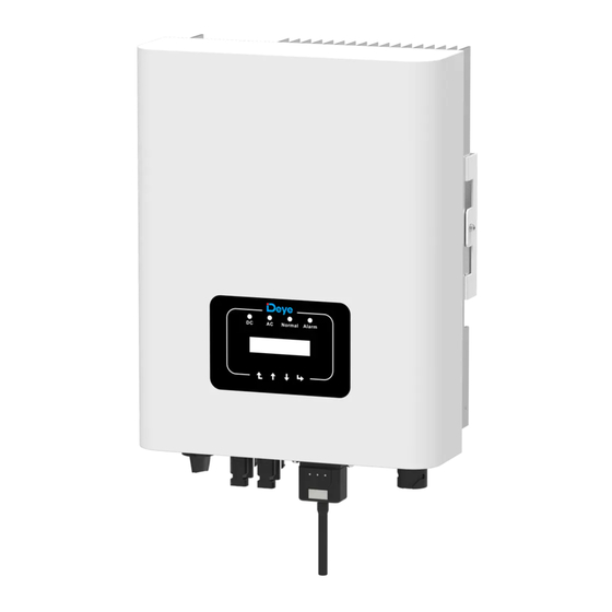
1.1 Appearance Introduc�on On-grid Inverter can convert solar panel DC power into AC power which can directly input to the grid. Its appearance is shown below.These models contain SUN-3K-G06, SUN-4K-G06, SUN-5K-G06, SUN-6K-G06, SUN-7K-G06, SUN-8K-G06,SUN-10K-G06, SUN-12K-G06. The following is collec�vely referred to as “inverter”. - Page 5 1.2 Parts list Please check the following table, to see whether all the parts are included in the package: Moun�ng stainless steel Grid-�ed PV String Inverter Wall moun�ng bracket x1 screws M4×12 DC+/DC- Plug connectors Stainless steel an�-collision AC power connectors x1 including metal terminal bolt M6×60 User...
- Page 6 2. Safety warnings and instruc�ons Improper use may result in poten�al electric shock hazards or burns. This manual contains important instruc�ons that should be followed during installa�on and maintenance. Please read these instruc�ons carefully before use and keep them for future reference. 2.1 Safety signs Safety symbols used in this manual, which highlight poten�al safety risks and important safety informa�on, are listed as follows:...
- Page 7 Shock Hazard: When PV module is exposed to sunlight, the output will generate DC voltage. Prohibit touching to avoid shock hazard. Shock Hazard: While disconnect the input and output of the inverter for maintenance, please waits for at least 5 mins un�l the inverter discharge the remnant electricity. High Temperature Hazard: Local temperature of inverter may exceed 80℃...
- Page 8 3. Opera�on Interface 3.1 Interface View Normal Alarm Pic 3.1 Front panel display 3.2 Status Indicator There are four LED status indicator lights in the front panel of the inverter. Please see table 3.1 for details. Indicator status Explanation Inverter detects DC input ●DC off...
- Page 9 3.3 Bu�ons There are four keys in the front panel of the Inverter(from le� to right): Esc, Up, Down and Enter keys. The keypad is used for: ● Scrolling through the displayed op�ons (the Up and Down keys); ● Access to modify the adjustable se�ngs (the Esc and Enter keys). Down Enter 3.4 LCD Display...
- Page 10 4. Product installa�on 4.1 Select installa�on loca�on To select a loca�on for the inverter, the following criteria should be considered: WARNING: Risk of fire ● Do not install the inverter in areas containing highly flammable materials or gases. ● Do not install the inverter in poten�ally explosive atmospheres. ●...
- Page 11 ● Install on a wall or strong structure capable of bearing the weight. ● Install ver�cally with a maximum incline of +/-15°. If the mounted inverter is �lted to an angle greater than the maximum noted, heat dissipa�on can be inhibited, and may result in less than expected output power.
- Page 12 ≥500mm ≥500m Pic 4.3 Installa�on Gap 4.2 Inverter Installa�on The inverter is designed according to the wall mounted type installa�on, please use the wall mounted (the brick wall of the expansion bolt) when installing. Anchoring Moun�ng bracket Stainless steel screws Inverter Pic 4.4 Inverter Installa�on - 10 -...
- Page 13 Procedure shows below: 1. Locate on the appropriate wall according to the bolt posi�on on the moun�ng bracket, then mark the hole.On the brick wall, the installa�on must be suitable for the expansion bolt installa�on. Pic 4.5 Inverter hanging plate installa�on 2.
- Page 14 5 Electrical Connec�on 5.1 DC input terminal connec�on 1. Switch the Grid Supply Main Switch(AC)OFF. 2. Switch the DC lsolator OFF. 3. Assemble PV input connector to the inverter. Warning: When using PV modules, please ensure the PV+ & PV- of solar panel is not connected to the system ground bar Safety Hint: Before connec�on, please make sure the polarity of the output voltage of PV...
- Page 15 The steps to assemble the DC connectors are listed as follows: a)Strip off the DC wire about 7mm, disassemble the connector cap nut (see picture 5.3). Pic 5.3 Disassemble the connector cap nut b) Crimping metal terminals with crimping pliers as shown in picture 5.4. Pic 5.4 Crimp the contact pin to the wire c) Insert the contact pin to the top part of the connector and screw up the cap nut to the top part of the connector.
- Page 16 DC input current should be 20A. if exceeds, it may damage the inverter and it is not covered by Deye warranty. 5.2 AC input terminal connec�on Do not close the DC switch a�er the DC terminal is connected.Connect the AC terminal to the AC side of the inverter, the AC side is equipped with Three phase AC terminals that can be conveniently connected.
- Page 17 The AC output connector is divided into three parts: matching socket, sleeve and sealing- sleeve, as shown in picture 5.7, the steps are as follows: Step 1: Remove the cable sealing ring and sleeve in sequence from the AC connector. Step 2: Use strippers to strip the protec�ve sheath and insula�on layer of the AC cable to the right length, as shown in Picture 5.8.
- Page 18 Pic 5.9 AC Connector Hole Pa�ern Step 5: Set the sleeve and sealing ring in place. Step 6: Connect the terminals to the inverter as shown in picture 5.10. Pic 5.10 AC input connec�on - 16 -...
- Page 19 5.3 The connec�on of the ground line Good grounding is good for resis�ng surge voltage shock and improving EMI perfor- mance.Therefore, before connec�ng AC, DC and communica�on cables, you need to ground the cable firstly. For a single system, just ground the PE cable. For mul�ple machine systems, all PE cables of the inverter need to be connected to the same grounding copper platoon to ensure the equipoten�al connec�on.
- Page 20 In order to protect the inverter AC connec�on, it is recommended to install a circuit breaker to prevent overcurrent. See table 5.3 below. Rated output Rated output Current for protection Inverter voltage(V) current(A) device(A) SUN-3K-G06 220/230 4.5/4.3A SUN-4K-G06 220/230 6.1/5.8A SUN-5K-G06 220/230 7.6/7.2A...
-
Page 21: Startup And Shutdown
5.6 Installa�on of datalogger When installing the WiFi s�ck, tear off the sealing strip on the inverter. Insert the datalogger into the interface and fix it with a screw. The configura�on of the datalogger needs to be performed a�er various electrical connec�ons have been completed and the inverter DC power on. - Page 22 6.1 Start up the inverter When star�ng up the three phase string inverter, should fellow steps below: 1. Star�ng switch on the AC breaker. 2. Turn on the DC switch of the photovoltaic module, and if the panel provides sufficient star�ng voltage and power, the inverter will start.
- Page 23 7. Zero-export func�on via energy meter There're two kinds of energy meters for this series inverter. First type is Eastron SDM630-Modbus V2 which is able to measure the Max. 100A current directly. More details please refer to Pic 7.1 & 7.2. For the Eastron SDM630 MCT 40mA, it needs external CT to measure the current.
- Page 24 1 2 3 4 5 6 7 8 Eastron (1,2,3,4) (5,6,7,8) B A G RS 485 RS 485 B RS 485 A Eastron SDM630-Modbus V2 Inverter Solar Panel array AC Breaker RS 485 Male connector Family load VCC_5V 485_B N L3 L2 L1 RS 485 Female connector L1 L2 L3 N...
- Page 25 9 1 0 11 1 2 1 3 1 4 1 5 1 6 1 7 1 8 1 9 2 0 Eastron 15 16 17 18 19 20 1 2 3 4 Grid voltage Auxiliary Current inputs sampling power supply 1 4 1 3 1 2 RS 485 Eastron SDM630MCT...
- Page 26 Three-Phase Smart Meter (1,4,7,10) (3,6,9,10) RS 485 CHNT DTSU666 Pic 7.5 CHNT meter Inverter Solar Panel array AC Breaker RS 485 Male connector Family load L1 L2 L3 N VCC_5V 485_B RS 485 Female connector Three-Phase Smart Meter meter 485_A L1 L2 L3 N 485_A 485_B...
- Page 27 7.1 Mul�ple strings and parallel connec�on meters This applica�on is that when the string inverters work in parallel, there is only one power grid and one load, and only one meter can be connected to prevent reverse current, so only this many-to-one an�-reverse current connec�on can be connected. If there’s several inverters in a plant, also it can use 1pcs meter to realize zero export func�on.For example,if there’s 3pcs inverter in the system with 1pcs meter.We need to setup 1pcs inverter as the master and others setup as slaves.
- Page 28 Name Descrip�on Range AVG: Average power of three phase is zero exported. Exp_Mode MIN: Phase with minimum load power is zero AVG/MIN exported, while the other two phase may be in purchase mode. CT ra�o of power grid side meter when extern CT_Ra�o 1-1000 CT is applied.
- Page 29 1 2 3 4 5 6 7 8 Eastron (1,2,3,4) (5,6,7,8) B A G RS 485 RS 485 B RS 485 A Eastron SDM630-Modbus V2 Pic 7.8 Eastron meter Grid Master(Mst) L1 L2 L3 N RS485 485_B 485_A VCC_5V 485_B RS 485 Female connector Slave2(Slv2)
- Page 30 9 1 0 11 1 2 1 3 1 4 1 5 1 6 1 7 1 8 1 9 2 0 Eastron 1 2 3 4 15 16 17 18 19 20 Grid voltage Auxiliary Current inputs sampling power supply 1 4 1 3 1 2 RS 485 RS 485 A RS 485 B...
- Page 31 Three-Phase Smart Meter (1,4,7,10) (3,6,9,10) RS 485 Pic 7.12 CHNT meter CHNT DTSU666 Master(Mst) AC Breaker Solar Panel array Slave1(Slv1) AC Breaker Solar Panel array Slave2(Slv2) AC Breaker Solar Panel array AC Breaker load VCC_5V 485_B RS 485 Female connector 485_A Master(Mst) RS485...
-
Page 32: System Param
7.2 Use of zero-export func�on When the connec�on is completed, the following steps should be refered to use this func�on: 1. Turn on the AC switch. 2. Turn on the DC switch, wai�ng for the inverter's LCD is turned on. 3. - Page 33 7.3 Notes while using zero export func�on For your safety and the opera�on of limiter func�on of the inverter, we put forward the following sugges�ons and precau�ons: Safety Hint: Under zero export mode we strongly recommend that the two PV arrays are formed by the same number of PV panels of the same size, which will make the inverter more responsive to limit the power.
- Page 34 And then choose your system type as “Self-consump�on” Edit Plant Done Cancel Address : Basic Info YongJian g Road, Beilum,NingBo, 315806, China System Info Yield Info Coordinates : Owner Info Longitude 19.03 ” Latitude 36.11 ” Time Zone : Creation Time : 2020/04/08 (UTC+08:00) Beijing,Chongqing,Hong Kong,Urumqi System Info...
-
Page 35: General Opera�On
8. General Opera�on During normal opera�on, the LCD shows the current status of the inverter, including the current power, total genera�on, a bar chart of power opera�on and inverter ID,etc. Press the Up key and the Down key to see the current DC voltage, DC current, AC voltage, AC current,in- verter radiator temperature,so�ware version number and Wifi... - Page 36 P1-P6 Vstart Q1-Q6 Vstop P1-P6 PF1-PF6 Pstart Pstop RmpTime Ac�veP PmpTime Q-Mode PtUsed V1-V6 Q1-Q6 VRated Q(%) ReactP Exp_Mode Fun- ISO AUTO CT_Ra�o 0 EASTRON Fun RCD ACREL FeedIn SelfCheck CHNT Shunt ShuntQTY Island Generator AUTO Meter G.CT EASTRON Setup G.MFR ACREL Limiter...
- Page 37 *Note: These parameters will be avaiable a�er the meter is INMETRO connected successfully. Otherwise, it won't show. EN50549 EN50438 IEC61727 CUSTOM VDE_4105 UTE_C15 RD1699 CEI_0_21 G98_G99 AS4777(.2) NB/T 32004 GridStanderd Protect Param OverVolt Lv3-Lv1 Advanced Point 240.0V Back Delay 1000ms UnderVolt Lv1-Lv3 Point 235.0V Delay 1000ms...
- Page 38 8.1 The ini�al interface From the ini�al interface, you can check PV power, PV voltage, grid voltage, inverter ID, model and other infoma�on. Power: Power: State: Standby State: Com.Error Pic 8.2 The ini�al interface Press UP or Down, you can check inverter DC voltage, DC current, AC voltage, AC current and inverter temperature.
- Page 39 ImpEp: Daily energy purchased from grid; ImpEp: 0.00KWh Total: Total energy purchased from grid. Total : 0.00KWh Pic 8.11 Electrical energy ExpEp: Daily energy sold to grid; ExpEp: 0.00KWh Total: Total energy sold to grid. Total : 0.00KWh Pic 8.12 Electrical energy 8.2 Submenus in the Main Menu There are five submenus in the Main Menu.
- Page 40 8.2.3 ON/OFF se�ng ON / OFF << Turn ON << Setup Turn OFF Turn ON Turn OFF << Cancel << Cancel Pic 8.15 ON/OFF se�ng When the inverter is turned off, it stops working immediately, and go to standby mode and then will go to self-test program again.
- Page 41 8.3 System param se�ng System Param includes �me set, language set, display set and factory reset. Time Set << Display Set Language Set Factory Reset << Factory Reset Set Restore << Pic 8.18 System Param 20200522 OK English << Polski 08:11:21 Cancel Pic 8.19 Time Bright Keep...
- Page 42 8.4 Running param set Warning: Password required-- only for access-authorized engineer. Un-authorized access may avoid the warranty. The ini�al password is 1234. PassWord Pic 8.25 Password Vref 0.0V ActiveP ReactP 0.0% << Q-Mode OFF << Fun RCD OFF << -1.000 Fun ISO OFF <<...
- Page 43 Name Descrip�on Range Ac�veP Adjust the output ac�ve power in % 0-110% OFF/Q(P)/PF(P) Q-Mode Mul�ple reac�ve power control modes /Q(U)/PF/Q(%) Grid reference voltage for func�ons Vref 80-260V including Q(U),PF(P),P(U)etc. ReactP Adjust reac�ve power output in % -100%-+100% Power Fator -1-0.8~+0.8-1 Fun_ISO Insula�on resistance detec�on ON/OFF...
- Page 44 UF-Uprate OFF <- OF-Derate OFF <- WGra 0.000% WGra 0.0% << WGraStr 0.0% PowerLim << Pic 8.28 HardLimitation HardLimitation Enable OFF << Point 0.0% << SoftLimitation << Cancel Enable OFF << Pic 8.29 LVRT HVRT OFF << Sunspec OFF << Sunspec OFF <<...
- Page 45 Name Descrip�on Range Arc-fault detec�on func�on ON/OFF/CLR Ac�ve power response to over- ON/OFF/HYS OF-Derate frequency Ac�ve power response to under- ON/OFF UF-Uprate frequency power response to grid voltage ON/OFF devia�on ON/OFF voltage ride through func�on LVRT ON/OFF HVRT voltage ride through func�on Hard/so�...
- Page 46 Over-frequency Response This series inverter provides “over-frequency response” func�on. Long pressing the “OFD Mode” to enter the “over-frequency response” se�ng menu. OF-Derate ON <- OFDMode HYS <- OF-Derate OFF <- Tab. 11-4 Definition of Over-frequency Response Parameters Parameter Range Description Fstr 45HZ-65HZ The Start frequency value for over-frequency response.
- Page 47 When the frequency exceeds : 51.5Hz, the inverter output should stop (ie 0 W). Fstop When the frequency is lower than : 51.5 Hz, the inverter will linearly increase the power Fstop output with a gradient of 100% Pmax/Hz un�l it reaches : 50.5 Hz.
- Page 48 "Q(U)" Mode The reac�ve power output of the inverter varies in response to the grid voltage. "Q(P)" Mode The reactive power output by the inverter is controlled by the active power of the inverter. "PF(P)" Mode The PF is controlled by the active power of the inverter. “PU”...
- Page 49 U/Vref (U1,P1) (U2,P2) (U3,P3) (U4,P4) P/Pn Pic 8.33 Ac�ve Power Regula�on Curve in PU Curve Parameter Range Descrption Value of P/Pn at point (P1,U1) on the PU mode 0%-110% Pn curve Grid voltage limit at point (P1,U1) on the PU mode 0% -150% Vref curve Value of P/Pn at point (P2,U2) on the PU mode...
- Page 50 “Q(U)” Mode ActiveP Pstart 0.0% << QMode Pstop Q(U) <- 20.0% RmpTime 0.0% << PtUsed 0 << 0.0% 0.0% << 0.0% << 0.0% 0.0% 0.0% << 0.0% << 0.0% 0.0% 130.0% << 0.0% Cancel << 30.0% Pic 8.34 - 48 -...
- Page 51 (U1,Q1) Upper Q/Pn lnd (U2,Q2) (U4,Q4) Grid Voltage (U3,Q3) (U5,Q5) Lower Q/Pn Cap (U6,Q6) Pic 8.35 Reac�ve Power Regula�on Curve in Q(U) Curve - 49 -...
- Page 52 Parameter Range Description The QU mode starts when the active power Pstart 0%-130% Rate out power is greater than this value The QU mode stops when the active power 0%-130% Rate out power Pstop is less than this value Value of Q/Pn at point (U1,Q1) on the Q(U) -60% -60% Q/Pn mode curve Grid voltage limit at point (U1,Q1) on the...
- Page 53 “Q(P)” Mode The reactive power output by the inverter is controlled by the active power of the inverter. Upper Q/Pn lnd (P1,Q1) P2(P2,Q2) P/Pn P4(P4,Q4) P3(P3,Q3) P5(P5,Q5) Lower P6(P6,Q6) Q/Pn Cap Pic 8.36 Reac�ve Power Regula�on Curve in Q(P) Mode ActiveP 20.0% 0.0% <<...
- Page 54 Parameter Range Description Power value/Pn at point (P1,Q1) on the Q(P) mode 0%-100% Pn curve Reac�ve power value at point (P1,Q1) on the Q(P) -60% -60% Q/Pn mode curve Power value/Pn at point (P2,Q2) on the Q(P) mode 0%-100% Pn curve Reac�ve power value at point (P2,Q2) on the Q(P) -60% -60% Q/Pn...
- Page 55 "PF(P)" Mode The output power factor is controlled by the active power of the inverter. Vstart 0.0% 0.0% Vstop 0.0% -1.000 << 0.0% 0.0% -1.000 << -1.000 << 0.0% 0.0% -1.000 << -1.000 << 0.0% RmpTime Cancel << -1.000 << PF lagging P1(P1,PF1) P2(P2,PF2)
- Page 56 Parameter Range Description The PFP mode is enable when grid Vstart 0-150% Vref voltage is greater than Vstart The PFP mode is disable when grid voltage Vstop 0-150% Vref is less than Vstop Power value at point (PF1,P1) on the PF(P) 0-110% Pn Curve PF value at point (PF1,P1) on the PF(P)
- Page 57 8.5 Protect Param Warning: Engineer Only. We will set the param depends on the safety requirements, so customers don't need to reset it. The password is same as 8.4 Running param PassWord GridStanderd << Advanced Back << Pic 8.32 Password INMETRO EN50438 EN50549...
- Page 58 OverVolt OverVolt Point 240.0V << Delay 1000ms << OverVolt OverVolt Point 240.0V << Delay 1000ms << UnderVolt UnderVolt Point 235.0V << Delay 1000ms << UnderVolt UnderVolt Point 235.0V << Delay 1000ms << UnderVolt UnderVolt Point 235.0V << Delay 1000ms << OverFreq OverFreq Point...
- Page 59 UnderFreq Lv2 UnderFreq Lv2 Point 48.00Hz << Delay 1000ms << UnderFreq Lv3 UnderFreq Lv3 Point 48.00Hz << Delay 1000ms << Reconnection Reconnection 0.0V << Vdown 0.0V << Reconnection Reconnection 0.00Hz << Fdown 0.00Hz << OV 10 Minutes 10 Minutes Enable OFF <<...
-
Page 60: Repair And Maintenance
9. Repair and Maintenance String type inverter doesn’t need regular maintenance. However,debris or dust will affect heat sink’s thermal performance. It is be�er to clean it with a so� brush. If the surface is too dirty and affect the reading of LCD and LED lamp, you can use wet cloth to clean it up. High Temperature Hazard: When the device is running, the local temperature is too high and the touch can cause burns. - Page 61 Check the solar panel output connec�on. Failure in reading memory (EEPROM). Restart the inverter if the Read the memory error fault s�ll exists, contact your installer or Deye service. Failure in wri�ng memory (EEPROM). Restart the inverter if the Write the memory error fault s�ll exists, contact your installer or Deye service.
- Page 62 3. Check if the inverter FW version is suitable for the hardware. 4. Restart the inverter, if the error s�ll exists, please contact your installer or Deye service. DC leakage flow fault Hardly appear the code. Never ever happened so far.
- Page 63 1. Check AC current sensor and its circuit. AC over current(one cycle) 2. Restart the inverter, if the fault s�ll exists, contact your installer or Deye service. DC over current Hardly appear the code. Never ever happened so far. Check the AC voltage protec�on se�ng. And Check if the AC AC Line W,U over voltage cable is too thin.Check the voltage difference between LCD and...
- Page 64 DC busbar voltage is too low then showing F56, maybe Loss of driver or need update firmware. 3. Restart the inverter, if the fault s�ll exists, contact your installer or Deye service. AC reverse irriga�on AC reverse irriga�on. AC grid U over current Hardly appear the code.
- Page 65 11.Specifica�on SUN-3K- SUN-4K- SUN-5K- SUN-6K- Model Input Side Max.DC Power(kW) Max.DC Input Voltage(V) 1000 Start-up DC Input Voltage(V) MPPT Opera�ng Range(V) 120~850 Max.DC Input Current(A) 13+13 Max. Short Circuit Current (A) 19.5+19.5 Number of MPPT/Strings per MPPT MAX inverter backfeed current (A) Output Side Rated Output Power(kW) Max.Ac�ve Power(kW)
- Page 66 General Data DC Connec�on MC-4 mateable AC Connec�on IP65 rated plug Display LCD1602 Interface RS485/RS232/Wifi/LAN - 64 -...
- Page 67 Model SUN-7K-G06 SUN-8K-G06 SUN-10K-G06 SUN-12K-G06 Input Side Max.DC Power(kW) 10.4 15.6 Max.DC Input Voltage(V) 1000 Start-up DC Input Voltage(V) 250V MPPT Opera�ng Range(V) 120~850 200~850 Max.DC Input Current(A) 13+13 Max. Short Circuit Current (A) 19.5+19.5 Number of MPPT/Strings per MPPT MAX inverter backfeed current (A) Output Side Rated Output Power(kW)
- Page 68 General Data DC Connec�on MC-4 mateable AC Connec�on IP65 rated plug Display LCD1602 Interface RS485/RS232/Wifi/LAN 2022-02-02 Ver 2.3 - 66 -...
- Page 69 Add: No.26-30, South Yongjiang Road, Beilun, 315806, Ningbo, China Tel: +86 (0) 574 8622 8957 Fax: +86 (0) 574 8622 8852 E-mail: service@deye.com.cn Web: www.deyeinverter.com...
Need help?
Do you have a question about the SUN-3K-G06 and is the answer not in the manual?
Questions and answers