
Related Manuals for Deye SUN-30K-G04


Summary of Contents for Deye SUN-30K-G04
- Page 1 Grid-connected PV Inverter SUN-��K-G�� SUN-��K-G�� SUN-��K-G�� SUN-��K-G�� User Manual...
-
Page 2: Table Of Contents
Contents �. Introduction ………………………………………………………… - � - �.� Appearance Introduction …………………………………………………… - � - �.� Parts list ……………………………………………………………… - � - �. Safety warnings and instructions ……………………………………… - � - �.� Safety signs ………………………………………………… - � - �.� Safety instructions …………………………………………………... - Page 3 �. Zero-export function via energy meter …………………………… - �� - �.� Use of zero-export function ………………………………………………… - �� - �.� Sensor Clamp(optional) ……………………………………………… - �� - �.� Use of limiter function ………………………………………………… - �� - �.� How to browse the load power of your PV grid-tieplant on monitoring platform? - ��...
-
Page 4: Introduction
Documents must be stored carefully and be available at all times. Contents may be periodically updated or revised due to product development. The information in this manual is subject to change without notice.The latest manual can be acquired via service@deye.com.cn Photovoltaic Grid-connected System... -
Page 5: Parts List
�.� Parts list Please check the following table, to see whether all the parts are included in the package: Mounting stainless steel screws M��� Grid-tied PV String Inverter Wall mounting bracket x� x� x� User manual DC+/DC- Plug connectors Stainless steel anti-collision including metal terminal bolt M���... -
Page 6: Safety Warnings And Instructions
�. Safety warnings and instructions Improper use may result in potential electric shock hazards or burns. This manual contains important instructions that should be followed during installation and maintenance. Please read these instructions carefully before use and keep them for future reference. �.�... -
Page 7: Notes For Using
Shock Hazard: When PV module is exposed to sunlight, the output will generate DC voltage. Prohibit touching to avoid shock hazard. Shock Hazard: While disconnect the input and output of the inverter for maintenance, please waits for at least � mins until the inverter discharge the remnant electricity. High Temperature Hazard: Local temperature of inverter may exceed ��℃... -
Page 8: Operation Interface
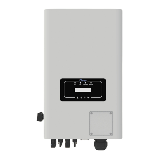
�. Operation Interface �.� Interface View Normal Alarm Pic �.� Front panel display �.� Status Indicator There are four LED status indicator lights in the front panel of the inverter. Please see table �.� for details. Indicator status Explanation Inverter detects DC input off... -
Page 9: Buttons
�.� Buttons There are four keys in the front panel of the Inverter(from left to right): Esc, Up, Down and Enter keys. The keypad is used for: Scrolling through the displayed options (the Up and Down keys); ● Access to modify the adjustable settings (the Esc and Enter keys). ●... -
Page 10: Product Installation
�. Product installation 4.1 Select installa�on loca�on To select a location for the inverter, the following criteria should be considered: WARNING: Risk of fire Do not install the inverter in areas containing highly flammable materials or gases. ● Do not install the inverter in potentially explosive atmospheres. ●... - Page 11 Install on a wall or strong structure capable of bearing the weight. ● Install vertically with a maximum incline of +/-��°. If the mounted inverter is tilted to an ● angle greater than the maximum noted, heat dissipation can be inhibited, and may result in less than expected output power.
-
Page 12: Inverter Installation
≥���mm ≥���mm Pic �.� Installation Gap �.� Inverter Installation The inverter is designed according to the wall mounted type installation, please use the wall mounted (the brick wall of the expansion bolt) when installing. Anchoring Mounting bracket Stainless steel screws Inverter Pic �.�... - Page 13 Procedure shows below: �. Locate on the appropriate wall according to the bolt position on the mounting bracket, then mark the hole.On the brick wall, the installation must be suitable for the expansion bolt installation. Pic �.� Inverter hanging plate installation �.
-
Page 14: Electrical Connection
5 Electrical Connec�on �.� PV Module Selection: When selecting proper PV modules, please be sure to consider below parameters: �) Open circuit Voltage (Voc) of PV modules not exceeds max. PV array open circuit voltage of inverter. �) Open circuit Voltage (Voc) of PV modules should be higher than min. start voltage. �) The PV modules used to connected to this inverter shall be Class A rating certified according to lEC �����. - Page 15 Safety Hint: Please use approved DC cable for PV system. Cross section(mm ) Cable type Range Recommended value Industry generic PV cable �.�~�.� �.�(��AWG) (model: PV�-F) (��~��AWG) Table �.� DC Cable Specifications The steps to assemble the DC connectors are listed as follows: a) Strip off...
-
Page 16: Ac Input Terminal Connection
Max. DC input current should be ��A. if exceeds, it may damage the inverter and it is not covered by Deye warranty. �.� AC input terminal connection Do not close the DC switch after the DC terminal is connected.Connect the AC terminal to the AC side of the inverter, the AC side is equipped with Three phase AC terminals that can be conveniently connected. - Page 17 L� L� L� Pic �.� AC input connection Warning: Be sure that AC power source is disconnected before attempting to wire it to the unit. �. Before making Grid port connection, be sure to turn off AC baeaker or disconnector first. �.
-
Page 18: The Connection Of The Ground Line
�.� The connection of the ground line Good grounding is good for resisting surge voltage shock and improving EMI performance.There- fore, before connecting AC, DC and communication cables, you need to ground the cable firstly. For a single system, just ground the PE cable. For multiple machine systems, all PE cables of the inverter need to be connected to the same grounding copper platoon to ensure the equipoten- tial connection. -
Page 19: Max. Over Current Protection Device
�.� Max. over current protection device In order to protect the inverter AC connection, it is recommended to install a circuit breaker to prevent overcurrent. See table �.� below. Rated output Rated output Current for protection Inverter voltage(V) current(A) device(A) SUN-��K-G��... -
Page 20: Installation Of Datalogger
�.� Installation of datalogger When installing the WiFi stick, tear off the sealing strip on the inverter. Insert the datalogger into the interface and fix it with a screw. The configuration of the datalogger needs to be performed after various electrical connections have been completed and the inverter DC power on. -
Page 21: Start Up The Inverter
�.� Start up the inverter When starting up the three phase string inverter, should fellow steps below: �. Starting switch on the AC breaker. �. Turn on the DC switch of the photovoltaic module, and if the panel provides sufficient starting voltage and power, the inverter will start. - Page 22 7. Zero-export func�on via energy meter There're two kinds of energy meters for this series inverter. First type is Eastron SDM���-Mod- bus V� which is able to measure the Max. ���A current directly. More details please refer to Pic �.� & �.�. For the Eastron SDM��� MCT ��mA, it needs external CT to measure the current. The CT power range is from �A-����A.
- Page 23 � � � � � � � � L� L� L� Eastron L� L� L� Gird Load (�,�,�,�) (�,�,�,�) B A G RS ��� � � � � RS ��� B RS ��� A Eastron SDM���-Modbus V� Inverter Solar Panel array WIFI Meter RS485...
- Page 24 � � � � � � � � L� L� L� Eastron L� L� L� Gird Load (�,�,�,�) (�,�,�,�) B A G RS ��� � � � � RS ��� B RS ��� A Eastron SDM���-Modbus V� Inverter Solar Panel array WIFI Meter RS485...
- Page 25 � � � � � � � � � � � � � � � � � � � � � � � L� P� P� L� Eastron P� P� S � S� L� P� P� S � S � S �...
- Page 26 � � � � � � � � � � � � � � � � � � � � � � � L� P� P� L� Eastron P� P� S � S� L� P� P� S � S � S �...
- Page 27 � � � �� � � � � � � �� L� Grid Load L� Three-Phase Smart Meter (�,�,�,��) (�,�,�,��) L� �� �� RS ��� �� �� � � � �� CHNT DTSU��� Pic �.� CHNT meter Inverter Solar Panel array WIFI Meter RS485...
- Page 28 � � � �� � � � � � � �� L� Grid Load L� (�,�,�,��) Three-Phase Smart Meter (�,�,�,��) L� �� �� RS ��� �� �� � � � �� CHNT DTSU��� Pic �.�� CHNT meter Inverter Solar Panel array WIFI Meter RS485...
- Page 29 � � � �� �� �� �� �� �� �� � � � �� L� L� Three-Phase Smart Meter L� ���/���V, �~���A/��mA ��/��Hz �� �� Phase A current =�.���A �� �� �� �� �� �� �� �� RS��� � � �...
- Page 30 � � � �� �� �� �� �� �� �� � � � �� L� L� Three-Phase Smart Meter L� ���/���V, �~���A/��mA ��/��Hz �� �� Phase A current =�.���A �� �� �� �� �� �� �� �� RS��� � � �...
- Page 31 �.� Multiple strings and parallel connection meters This application is that when the string inverters work in parallel, there is only one power grid and one load, and only one meter can be connected to prevent reverse current, so only this many-to-one anti-reverse current connection can be connected.
- Page 32 Name Description Range AVG: Average power of three phase is zero exported. MIN: Phase with minimum load power is zero Exp_Mode AVG/MIN exported, while the other two phase may be in purchase mode. CT ratio of power grid side meter when extern CT is CT_Ratio �-����...
- Page 33 � � � � � � � � L� L� L� Eastron L� L� L� Gird Load (�,�,�,�) (�,�,�,�) B A G RS ��� � � � � RS ��� B RS ��� A Eastron SDM���-Modbus V� Master(Mst) Grid L� L� L� N RS���...
- Page 34 � � � � � � � � L� L� L� Eastron L� L� L� Gird Load (�,�,�,�) (�,�,�,�) B A G RS ��� � � � � RS ��� B RS ��� A Eastron SDM���-Modbus V� Generator Master(Mst) L� L� L� N RS���...
- Page 35 � � � � � � � � � � � � � � � � � � � � � � � L� P� P� L� Eastron P� P� S � S� L� P� P� S � S � S �...
- Page 36 � � � � � � � � � � � � � � � � � � � � � � � L� P� P� L� Eastron P� P� S � S� L� P� P� S � S � S �...
- Page 37 � � � �� � � � � � � �� L� Grid Load L� Three-Phase Smart Meter (�,�,�,��) (�,�,�,��) L� �� �� RS ��� �� �� � � � �� CHNT DTSU��� Pic �.�� CHNT meter Master(Mst) AC Breaker WIFI L�...
- Page 38 � � � �� � � � � � � �� L� Grid Load L� Three-Phase Smart Meter (�,�,�,��) (�,�,�,��) L� �� �� RS ��� �� �� � � � �� CHNT DTSU��� Pic �.�� CHNT meter Master(Mst) AC Breaker WIFI L�...
- Page 39 � � � �� �� �� �� �� �� �� � � � �� L� L� Three-Phase Smart Meter L� ���/���V, �~���A/��mA ��/��Hz �� �� Phase A current =�.���A �� �� �� �� �� �� �� �� RS��� � � �...
- Page 40 � � � �� �� �� �� �� �� �� � � � �� L� L� Three-Phase Smart Meter L� ���/���V, �~���A/��mA ��/��Hz �� �� Phase A current =�.���A �� �� �� �� �� �� �� �� RS��� � � �...
- Page 41 �.� Use of zero-export function When the connection is completed, the following steps should be refered to use this function: �. Turn on the AC switch. �. Turn on the DC switch, waiting for the inverter's LCD is turned on. �.
- Page 42 �.� Notes while using zero export function For your safety and the operation of limiter function of the inverter, we put forward the follow- ing suggestions and precautions: Safety Hint: Under zero export mode we strongly recommend that the two PV arrays are formed by the same number of PV panels of the same size, which will make the inverter more responsive to limit the power.
- Page 43 And then choose your system type as “Self-consumption” Edit Plant Cancel Done Address : Basic Info YongJiang Road, Beilum,NingBo, ������, China System Info Yield Info Coordinates : Owner Info Longitude ��� �� ��.�� Latitude �� �� ��.�� ” ” Time Zone : Creation Time : ����/��/��...
- Page 44 8. General Opera�on During normal operation, the LCD shows the current status of the inverter, including the current power, total generation, a bar chart of power operation and inverter ID,etc. Press the Up key and the Down key to see the current DC voltage, DC current, AC voltage, AC current,inverter radiator temperature,software version number and Wifi...
- Page 45 P1-P6 Vstart Q1-Q6 Vstop P1-P6 PF1-PF6 Pstart Pstop RmpTime Ac�veP PmpTime Q-Mode PtUsed V1-V6 Q1-Q6 VRated Q(%) ReactP Exp_Mode Fun- ISO EXT_01 CT_Ra�o 0 ACREL Fun RCD EASTRON FeedIn CHNT SelfCheck Shunt AUTO ShuntQTY Island Generator AUTO Meter G.CT EASTRON Setup G.MFR ACREL...
- Page 46 *Note: These parameters will be avaiable after the meter is Brazil connected successfully. Otherwise, it won't show. EN50549-1-PL EN50549-1 IEC61727 CUSTOM VDE_4105 VDE_0126 Spain CEI_0-21 G98_G99 NB/T 32004-B Australia-A-C NEW Zealand E MEA Norway Switzerland GridStanderd Protect Param OverVolt Lv3-Lv1 Advanced Point 240.0V Back...
- Page 47 �.� The initial interface From the initial interface, you can check PV power, PV voltage, grid voltage, inverter ID, model and other infomation. Power: Power: State: Standby State: Com.Error Pic �.� The initial interface Press UP or Down, you can check inverter DC voltage, DC current, AC voltage, AC current and inverter temperature.
- Page 48 ImpEp: Daily energy purchased from grid; Total: Total energy purchased from grid. ImpEp: 0.00KWh Total : 0.00KWh Pic �.�� Electrical energy ExpEp: Daily energy sold to grid; Total: Total energy sold to grid. ExpEp: 0.00KWh Total : 0.00KWh Pic �.�� Electrical energy �.�...
- Page 49 �.�.� ON/OFF setting ON / OFF << Turn ON << Setup Turn OFF Turn ON Turn OFF << Cancel << Cancel Pic �.�� ON/OFF setting When the inverter is turned off, it stops working immediately, and go to standby mode and then will go to self-test program again.
- Page 50 �.� System param setting System Param includes time set, language set, display set and factory reset. Time Set << Display Set Language Set Factory Reset << Factory Reset Set Restore << Pic �.�� System Param 20200522 OK English << Polski 08:11:21 Cancel Pic �.��...
- Page 51 �.� Running param set Warning: Password required-- only for access-authorized engineer. Un-authorized access may avoid the warranty. The initial password is ����. PassWord Pic �.�� Password Vref 0.0V ActiveP ReactP 0.0% << Q-Mode OFF << Fun RCD OFF << -1.000 Fun ISO OFF <<...
- Page 52 Cancel << Pic �.�� Name Description Range ActiveP Adjust the output active power in % �-���% OFF/Q(P)/PF(P) Q-Mode Multiple reactive power control modes /Q(U)/PF/Q(%) Grid reference voltage for functions Vref ��-���V including Q(U),PF(P),P(U)etc. ReactP Adjust reactive power output in % -���%-+���% Power Fator -�-�.�~+�.�-�...
- Page 53 Name Descrip�on Range Arc-fault detection function ON/OFF/CLR Active power response to over- OF-Derate ON/OFF/HYS frequency Active power response to under- UF-Uprate ON/OFF frequency power response to grid voltage ON/OFF deviation LVRT voltage ride through function ON/OFF HVRT voltage ride through function ON/OFF PowerLim Hard/soft export limit control...
- Page 54 RCD SEN MIN << ARC SEN HIG << Back Back ARC SEN MID << Back Pic �.�� FUN_RCD Island SEN MIN << Island SEN HIG << Back Back Island SEN MID << Back Pic �.�� Island ARC SEN HIG << ARC SEN MID <<...
- Page 55 Over-frequency Response This series inverter provides “over-frequency response” function. Long pressing the “OFD Mode” to enter the “over-frequency response” setting menu. OF-Derate ON <- OFDMode HYS <- OF-Derate OFF <- Tab. �-� Definition of Over-frequency Response Parameters Parameter Range Description Fstr ��HZ-��HZ The Start frequency value for over -frequency response.
- Page 56 HardLimitation HardLimitation Enable OFF << Point 0.0% << SoftLimitation SoftLimitation Enable OFF << Point 0.0% << PTD_H 0.0S << Cancel M_OFF 0.0%<< Pic �.�� PowerLim Vstart 0.0% Cancel << Vsop 0.0% << Pic �.�� LVRT - �� -...
- Page 57 When the frequency exceeds Fstop: ��.�Hz, the inverter output should stop (ie � W). When the frequency is lower than Fstop: ��.� Hz, the inverter will linearly increase the power output with a gradient of ���% Pmax/Hz until it reaches Fstr: ��.� Hz. In the hysteresis mode, when the frequency is lower than Fstop: ��.�...
- Page 58 "OFF" Mode The reactive power regulation function is disabled. The PF is fixed at +�.��� Q(%) Adjust reactive power output in %. "PF" Mode The power factor (PF) is fixed and the reactive power is regulated by the parameter PF. The PF ranges from �.�...
- Page 59 U/Vref (U1,P1) (U2,P2) (U3,P3) (U4,P4) P/Pn Pic �.�� Active Power Regulation Curve in PU Curve Parameter Range Descrption Value of P/Pn at point (P�,U�) on the PU mode P� �%-���% Pn curve Grid voltage limit at point (P�,U�) on the PU mode U�...
- Page 60 “Q(U)” Mode ActiveP Pstart 0.0% << QMode Pstop Q(U) <- 20.0% RmpTime UrefAuto RmpUref PtUsed 0 << 0 << 0.0% << 0.0% << 0.0% 0.0% 0.0% << 0.0% << 0.0% 0.0% 0.0% << 130.0% << 0.0% 30.0% 0.0% Cancel << Pic �.��...
- Page 61 (U�,Q�) Upper Q/Pn lnd (U�,Q�) (U�,Q�) Grid Voltage (U�,Q�) (U�,Q�) Lower Q/Pn Cap (U�,Q�) Pic �.�� Reactive Power Regulation Curve in Q(U) Curve - �� -...
- Page 62 Parameter Range Description The QU mode starts when the active power Pstart �%-���% Rate out power is greater than this value The QU mode stops when the active power �%-���% Rate out power Pstop is less than this value Value of Q/Pn at point (U�,Q�) on the Q(U) Q�...
- Page 63 “Q(P)” Mode The reactive power output by the inverter is controlled by the active power of the inverter. Upper Q/Pn lnd (P1,Q1) P2(P2,Q2) P/Pn P4(P4,Q4) P3(P3,Q3) P5(P5,Q5) Lower P6(P6,Q6) Q/Pn Cap Pic �.�� Reactive Power Regulation Curve in Q(P) Mode ActiveP 20.0% 0.0% <<...
- Page 64 Parameter Range Description Power value/Pn at point (P1,Q1) on the Q(P) mode 0%-100% Pn curve Reac�ve power value at point (P1,Q1) on the Q(P) -60% -60% Q/Pn mode curve Power value/Pn at point (P2,Q2) on the Q(P) mode 0%-100% Pn curve Reac�ve power value at point (P2,Q2) on the Q(P) -60% -60% Q/Pn...
- Page 65 "PF(P)" Mode The output power factor is controlled by the active power of the inverter. Vstart 0.0% 0.0% Vstop 0.0% -1.000 << 0.0% 0.0% -1.000 << -1.000 << 0.0% 0.0% -1.000 << -1.000 << 0.0% RmpTime Cancel << -1.000 << PF lagging P�(P�,PF�) P�(P�,PF�)
- Page 66 Parameter Range Description The PFP mode is enable when grid Vstart �-���% Vref voltage is greater than Vstart The PFP mode is disable when grid voltage Vstop �-���% Vref is less than Vstop Power value at point (PF�,P�) on the PF(P) P�...
- Page 67 �.� Protect Param Warning: Engineer Only. We will set the param depends on the safety requirements, so customers don't need to reset it. The password is same as �.� Running param PassWord GridStanderd << Advanced Back << Pic �.�� Password Braszil EN50549-1 EN50549-1-PL <<...
- Page 68 OverVolt OverVolt Point 240.0V << Delay 1000ms << OverVolt OverVolt Point 240.0V << Delay 1000ms << OverVolt OverVolt Point 240.0V << Delay 1000ms << UnderVolt UnderVolt Point 235.0V << Delay 1000ms << UnderVolt UnderVolt Point 235.0V << Delay 1000ms << UnderVolt UnderVolt Point...
- Page 69 UnderFreq Lv2 UnderFreq Lv2 Point 48.00Hz << Delay 1000ms << UnderFreq Lv3 UnderFreq Lv3 Point 48.00Hz << Delay 1000ms << Reconnection Reconnection 0.0V << Vdown 0.0V << Reconnection Reconnection 0.00Hz << Fdown 0.00Hz << OV 10 Minutes 10 Minutes Enable OFF <<...
- Page 70 9. Repair and Maintenance String type inverter doesn’t need regular maintenance. However,debris or dust will affect heat sink’s thermal performance. It is better to clean it with a soft brush. If the surface is too dirty and affect the reading of LCD and LED lamp, you can use wet cloth to clean it up. High Temperature Hazard: When the device is running, the local temperature is too high and the touch can cause burns.
- Page 71 Check the solar panel output connection. Failure in reading memory (EEPROM). Restart the inverter if the Read the memory error F�� fault still exists, contact your installer or Deye service. Failure in writing memory (EEPROM). Restart the inverter if the Write the memory error F��...
- Page 72 �. Check if the inverter FW version is suitable for the hardware. �. Restart the inverter, if the error still exists, please contact your installer or Deye service. DC leakage flow fault Hardly appear the code. Never ever happened so far.
- Page 73 �. Check AC current sensor and its circuit. AC over current(one cycle) �. Restart the inverter, if the fault still exists, contact your installer or Deye service. DC over current Hardly appear the code. Never ever happened so far. Check the AC voltage protection setting. And Check if the AC AC Line W,U over voltage cable is too thin.Check the voltage difference between LCD and...
- Page 74 DC busbar voltage is too low then showing F��, maybe Loss of driver or need update firmware. �. Restart the inverter, if the fault still exists, contact your installer or Deye service. AC reverse irrigation AC reverse irrigation. AC grid U over current Hardly appear the code.
- Page 75 11.Specifica�on Model SUN-��K-G�� SUN-��K-G�� SUN-��K-G�� SUN-��K-G�� Input Side Max.DC Power(kW) ��kW ��.�kW ��.�kW ��.�kW Max.DC Input Voltage(V) ����V Start-up DC Input Voltage(V) ���V MPPT Operating Range(V) ���V~���V Rated DC input voltage(V) ���V MPPT Full Power Voltage Range(V) ���V-���V ���V-���V Max.DC Input Current(A) ��A+��A Max.
- Page 76 General Data DC Connection MC-� mateable AC Connection IP�� rated plug Display LCD���� Interface RS���/RS���/Wifi/LAN 2023-06-10 Ver 2.4 - �� -...
- Page 77 Add: No.�� South YongJiang Road, Daqi, Beilun, NingBo, China. Tel: +�� (�) ��� ���� ���� Fax: +�� (�) ��� ���� ���� E-mail: service@deye.com.cn Web: www.deyeinverter.com...
Need help?
Do you have a question about the SUN-30K-G04 and is the answer not in the manual?
Questions and answers