Table of Contents
Advertisement
Advertisement
Table of Contents

Related Manuals for Deye SUN-3.6K-G


Summary of Contents for Deye SUN-3.6K-G
- Page 1 Grid-tied PV String Inverter User Manual...
- Page 2 1. Introduction - 1 - ………………………………………………………… 1.1 Appearance Introduction - 1 - ………………………………………… 1.2 Parts list - 2 - ………………………………………………………… 2. Safety warnings and instructions - 3 - ……………………………………… 2.1 Safety signs - 3 - ………………………………………………………… 2.2 Safety instructions - 3 - …………………………………………………...
-
Page 3: Appearance Introduction
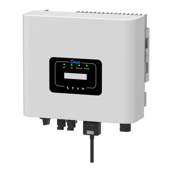
Single Phase String Power Inverter can convert solar panel DC power into AC power which can directly input to the grid. Its appearance is shown below.These models contain SUN-3.6K-G、SUN-5K-G、SUN-6K-G、SUN-7.5K-G and SUN-8K-G . The following is collectively referred to as‘inverter’. RS232/485... - Page 4 1.2 Parts list Please check the following table, to see whether all the parts are included in the package: Normal Alarm Pic1.3 Accessories drawing Description Grid-tied PV String Inverter Wall mounting bracket Mounting stainless steel screws M4×12 AC power connectors DC power connectors(including Inserted spring)...
-
Page 5: Safety Warnings And Instructions
2. Safety warnings and instructions Improper use of the inverter will cause electric shock and burn. During installation and maintenance. Please strictly follow the instructions on this manual. Please read the user manual carefully before using the inverter. And please keep the instructions properly for afterwards use. - Page 6 Warning: Inverter is non-isolated topology structure, hence must insure DC input and AC output are electrical isolated before operating the inverter. Strictly prohibit grounding the positive and negative poles of the PV string. Otherwise it will damage the inverter. Shock Hazard: Prohibit disassembling inverter case.
- Page 7 2.3 Notes for using The single phase string power inverter is designed and tested under related safety regulations. It can ensure the personal safety of the user. But as a electric device,it may cause shock or injury by incorrect operation. Please operate the unit under below requirements: 1.
-
Page 8: Operation Interface
3. Operation Interface 3.1Interface View Normal Alarm Pic 3.1 Panel 3.2 Status Indicator The inverter panel has 4 indicators, the left one is DC output indicator(green), indicates normal DC input power status. Beside is the AC indic ator(green),indicates normal AC connecting status. -
Page 9: Lcd Display
Indicator status Explanation Inverter detects DC input ●DC Low DC input voltage Grid Connected ●AC Grid Unavailable Under normal operating ● NORMAL Stop operating Detected faults or report faults ● ALARM Under normal operating 3.3 Buttons There are four buttons on the inverter panel:above is up and increase button (UP), below is down and decrease button (DOWN), left is ESC button (ESC), right is Enter button (ENTER). -
Page 10: Product Installation
4. Product installation 4.1 Select installation location When you receive the inverter and prepare to install it, please select a suitable location, should consider below factors: ● Ventilation—Must insure the air ventilation of the installation location,improper installation may cause overheating and effect the working efficiency and lifespan. ●... -
Page 11: Safety Hints
● Please select the wall with certain bearing capacity. ● When doing the installation, vertical slope cannot exceed +/-15°.Make sure no lateral tilt. Otherwise it will affect the function of the heat sink. Cause the output power lower than expected. ●... -
Page 12: Inverter Installation
≥500mm ≥500mm Pic4.3 Installation Gap 4.2 Inverter Installation The inverter is designed according to the wall mounted type installation, please use the wall mounted (the brick wall of the expansion bolt) when installing. Anchoring Mounting bracket M4*14 Stainless steel screws Inverter Pic4.4 Inverter Installation - 10 -... - Page 13 Inverter should be vertically installed, as shown in pic 4.5,installation procedure shows below: 1. Position the bolts on the appropriate wall according to the bolt positions on the mounting shelves and mark the holes. On the brick wall, the installation must be suitable for the expansion bolt installation.
-
Page 14: Electrical Connection
Pic4.6 Mounting of inverter 5 Electrical Connection The inverter has considered the convenience of the electrical connection while designing. we design fast connection for both DC and AC,all electrical connections conform to related standards of the country . 5.1 DC input terminal connection In order to safe connection, the electrical connection must follow below steps:... - Page 15 a). Make sure that the polarity of the output voltage of the solar panel is consistent with the polarity identified by the inverter b). Connect DC positive and negative to the inverter input terminal. (see picture 5.1 and picture 5.2) 5.1 DC “+ ”connector (MC4) 5.2 DC“-”connector (MC4) c).Making DC connection line Strip off the DC wire about 7mm, disassemble the connector...
- Page 16 2). Insert the contact pin into the connector housing until it locks in place. Screw the cap nut onto the connector housing. Torque to 2.5-3Nm(as shown in picture 5.5) Pic 5.5 connector with cap nut screwed on Traverse area(mm ) Outside diameter Cable type Recommended...
- Page 17 Cable Cable Cable item Cable Cable outer outer Specification 2.5mm 6mm 15~18mm 2.5mm 15~18mm Model SUN-3.6K-G SUN-5K/6K/7.5K/8K-G Breaker 30A/400V 40A/400V Max cable Outside cable(2+PE)20m Outside cable(2+PE)20m length Sheet 5.2 Cable information - 15 -...
- Page 18 1. Matching socket 2.Sleeve 3.Sealing core 4.Sealing nut 5.7 AC connector structure The AC output connector is divided into three parts: matching socket, sleeve and sealing sleeve, as shown in Picture 5.7, the steps are as follows: Step 1 Remove the cable sealing ring and sleeve in sequence from the AC connector. Step 2 Separate the sleeve from the matching socket,as shown in figure 5.7,the connector body has two locking holes, and press the locking valve in the hole inward to separate the matching socket from the sleeve.
- Page 19 Step 4 connect the cable (L, N, PE) into the sealing sleeve and sleeve. Step 5 use the hexagon screwdriver, loosen the bolts of the socket in turn, and insert each cable core into the corresponding jack,and set each screw. The connection hole of AC connection terminal labeling is shown in Picture 5.9.
-
Page 20: Inverter Monitoring Connection
5.3 The connection of the ground line Good grounding is good for resisting surge voltage surge and improving EMI performance. Therefore, before connecting AC, DC, and communication cables, you need to ground the cable firstly. For a single system , just ground the PE cable; For multiple machine systems, all PE cables of the inverter need to be connected to the same grounding copper platoon to ensure the equipotential connection. - Page 21 Phone GPRS Router Web Server WIFI 5.12 Internet monitoring solution 5.4.1 Installation of Wi-Fi Plug When the inverter is out of the factory, the installationlocation of Wifi plug is sealed by a sealed plate as shown in picture 5.13.When installing the Wifi Plug, remove the sealing plate, replace it with the sealing plate with square hole in the accessories, and tighten the screws.
- Page 22 5.13 Wifi Plug installation diagram 5.4.2 Configuration of Wi-Fi Plug For the configuration of Wi-Fi Plug, please refer to illustrations of the Wi-Fi Plug. - 20 -...
-
Page 23: Startup And Shutdown
6. Startup and Shutdown Before starting the inverter, make sure that the inverter can meet the following conditions, otherwise it may result in fire or damage to the inverter. In this case, we do not undertake any responsibility. At the same time, to optimize the system configuration, it is recommended that the two inputs be connected to the same number of photovoltaic modules. -
Page 24: Limiter Function
7. Limiter function The inverter has integrated export limitation function. The function is to adjust the output of inverter quickly according to the power of the user and solar panels, prevent the output of the inverter from being fed to the power grid. This limiter function is optional. If you buy the inverter with limiter, a current sensor will be included in the package which is necessary for limiter function. - Page 25 Normal Alarm Normal Alarm Solar Panel array Enter Down Sensor Load Utility Grid Pic 7.1 Connection diagram of limiter 7.2 Use of anti-backflow function When the connection is completed, the following steps should be referenced to use this function: 1.Turn on the AC switch 2.
- Page 26 Fun GFDI OFF << Limiter Pic 7.3 Limit switch 4. Operate the button [up down], move setting cursor to limit function and press the button [enter] .At this time you can turn on or turn off the limit function by choosing [up down] button, please press [enter] button to confirm when setting done.
- Page 27 7.3 Notes while using limit function For your safety and the operation of limiter function of the inverter, we put forward the following Suggestions and precautions: Warning: In limit function we strongly recommend that the two photovoltaic arrays are formed by the same number of photovoltaic panels of the same size, which will make the inverter more responsive to limit the power.
-
Page 28: General Operation
Warning: Do not change the operating parameters if non-professional when setting the limit function switch, otherwise inverter cannot able to normal operate. 8. General Operation During normal operation, the LCD shows the current status of the inverter, including the current power, total generation, a bar chart of power operation and inverter ID,etc. Press the Up key and the Down key to see the current DC voltage, DC current, AC voltage, AC current, inverter radiator temperature,software version number and Wifi connection state of the inverter. - Page 29 Power: 108W State: Normal 8.2 The initial interface Press UP or Down you can check inverter DC voltage, DC current, AC voltage,AC current, inverter temperature, software version information. PV1:276.2V 0.6A 8.3 PV input and DC current information You can check the PV information, the number of strings input, MPPT voltage and MPPT current.
-
Page 30: Device Information
You can check the inverter inside temp, LCD software Ver137 and inverter software Ver1400. There are two black spot in the bottom right corner. The first flash means inverter is communicating with LCD. The second flash means LCD is communicating with Wifi plug.There are four submenu in the Main Menu. -
Page 31: On/Off Setting
8.3 Fault Record Only can keep four fault record in the menu include time, customer can deal with it depends on the error code 1 F19 181017 07 2 F35 181015 08 8.11 Fault Record 8.4 ON/OFF setting << Turn ON Turn OFF 8.13 ON/OFF setting 8.5 Parameter setting... - Page 32 Param << Protect Param Protect Param << Comm. Param Pic8.10 Setting System Param includes time set, language set, display set and factory reset. Time Set << Language Set Display Set << Factory Reset Pic8.11 System Param 8.5.1.1 Time set 20181017 OK 08:45:57 Cancel Pic8.12 Time set...
- Page 33 8.5.1.2 Language set << English Pic8.13 Language set 8.5.2 Running Param Note: Password required-restricted access-authorized engineer only. Un-authorized access may avoid the warranty. The initial password is 1234 PassWord **** Pic8.14 Password << ActiveP 100% ReactiveP Fun GFDI OFF << Limiter Pic8.15 Running Param - 31 -...
- Page 34 8.5.3 Protect Param Note: Engineer Only. We will set the param depends on the safety requirements, so customers don’t need to reset it. The password is same as 8.5.2 Running param. << oo CHINA oo BRAZIL 00 EN50549 << 00 CUSTOM Pic8.16 Protect Param Note:...
-
Page 35: Repair And Maintenance
<< AC OverFreq 51.50Hz << AC LowFreq 47.50Hz Pic8.17 “CUSTOM” 9. Repair and Maintenance String type inverter doesn't need regular maintenance. However, debris or dust will affect heat sink's thermal performance. It is better to clean it with a soft brush. If the surface is too dirty and affect the reading of LCD and LED lamp, you can use wet cloth to clean it Warning:... - Page 36 requirements. Before leaving the factory, the inverter has undergone several rigorous tests to ensure that it can be operated reliably and permanently. 10.1 Error code In the case of failure the LCD screen will display an alarm message. In this case the inverter may stop feeding energy into the grid.
- Page 37 Error code Description Solutions 1. Measure the actual grid voltage and compare with inverter set value. if the grid voltage measured is higher than set value, and AC Line L, N over voltage then ask help from local electrically company for solution; Generally, the inverter will 2.
-
Page 38: Specification
1、Serial number of the inverter; 2、The distributor/dealer of the inverter(if acailable); 3、Installation date; 4、The descruotion of problem(include LCD'error code and LED starus indicator lights); 5、Your contact details. 11.Specification Model SUN-3.6K-G SUN-5K-G SUN-6K-G SUN-7.5K-G SUN-8K-G Energy source Grid-connected PV Input Side 4.68... - Page 39 DC Injection Current(mA) <0.5% Grid Frequency Range 47-52 or 57-62(optional) Efficiency Max.Efficiency 97.3% 97.5% 97.5% 97.7% 97.7% Euro Efficiency 97.1% 97.3% 97.3% 97.5% 97.5% MPPT Efficiency >99% DC reverse-polarity protection;AC short circuit protect- ion;AC output overcurrent protection;Output over- Protection voltage protection;Insulation resistance protection;Ground fault monitoring;Surge protection;Islanding protection;...
- Page 40 Add: No.26-30, South Yongjiang Road, Beilun, 315806, Ningbo, China Tel: +86 (0) 574 8622 8957 Fax: +86 (0) 574 8622 8852 E-mail: wutz@deye.com.cn Web: www.deyeinverter.com Ver: 1.4, 2020-05...
Need help?
Do you have a question about the SUN-3.6K-G and is the answer not in the manual?
Questions and answers