
Subscribe to Our Youtube Channel
Related Manuals for Federal Signal Corporation DS100X


Summary of Contents for Federal Signal Corporation DS100X
- Page 1 Directional Speaker Model DS100X 100-watt speaker For use in hazardous locations Description, Specifications, and Installation Manual 25500761 Rev. A0 0222 Printed in U.S.A. © Copyright 2022 Federal Signal Corporation...
- Page 2 A copy of this limited warranty can also be obtained by written request to Federal Signal Corporation, 2645 Federal Signal Drive, University Park, IL 60484, email to info@fedsig.com or call +1 708-534-3400.
-
Page 3: Table Of Contents
Using Optional Warning Lights ..........................25 Closing the Housing ............................27 Applications ................................28 Configuring the RF100X with the DS100X (120 VAC) ..................28 Wiring Power to the Interconnect Board ....................28 Wiring AC to the Interconnect Board ......................28 Wiring Audio to the Amplifier Board ......................28 Wiring Relays to the Interconnect Board ....................29... - Page 4 Configuring the 300VSC SelecTone with the DS100X (120 VAC) ..............30 Wiring Power to the Interconnect Board ....................30 Wiring Audio to the Amplifier Board ......................31 Getting Service ..............................32 Appendix A Wiring Diagrams ..........................33 Figures Figure 1 DS100X Speaker with 225XL light ......................11 Figure 2 Bracket attached to speaker........................16...
- Page 5 Tables Table 1 Ordering Information ..........................11 Table 2 Electrical ..............................11 Table 3 Hazardous Location Ratings ........................12 Table 4 Electrical Ratings .............................12 Table 5 Visual Indications .............................12 Table 6 Connectors (Interconnect board) ......................12 Table 7 Connectors and Indicator (Power Supply Board) .................12 Table 8 Connectors and Controls (Amplifier Board) ..................13 Table 9 Environmental and Physical ........................14 Table 10 Speaker Mounting Options ........................14...
-
Page 6: Safety Messages
• When DS100X Speakers are used out of doors, people indoors may not be able to hear the warning signals. Separate warning devices or procedures may be needed to effectively warn people indoors. - Page 7 For optimum sound distribution, do not install this speaker where objects would block any portion of the front of the DS100X Speaker. • Do not paint the DS100X Speaker. No finish or coating is required. Paint may obstruct the sound output, reducing the effectiveness of the horn. •...
- Page 8 File these instructions in a safe place and refer to them periodically. Give a copy of these instructions to recruits and trainees. Also give a copy to anyone who is going to service or repair the DS100X Speaker.
- Page 9 Safety Messages NOTICE is used to address practices not related to physical injury. Read and understand the information contained in this manual before attempting to install or service the siren. Description, Specifications, and Installation Manual Federal Signal www.fedsig.com...
-
Page 10: General Description
AC, it can use the Interconnect Board to activate AC-powered visual alert devices. When the DS100X is powered from DC, it brings power in from an outside source. The DS100X has a 1/2-inch NPT opening on the top of the speaker for simple installation of pipe mount devices such as strobes. -
Page 11: Ordering Information
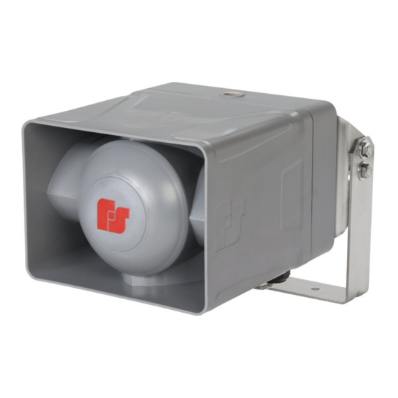
I-IP100-OMNI Omni directional option for speaker with hardware NOTE: You can connect the DS100X to other Federal Signal speakers. Contact Technical Support. See “Applications” on page 28. The following are pictures of the DS100X Speaker shown with optional 225XL Warning Light. -
Page 12: Table 3 Hazardous Location Ratings
• Pins 7 and 8 for relay out #4 Power in Power out Use to connect AC power to an additional DS100X unit. Local power Table 7 Connectors and Indicator (Power Supply Board) Transformer Primary 1 – Primary #2 upper, BLU 2 –... -
Page 13: Table 8 Connectors And Controls (Amplifier Board)
Specifications AC Power Input 1 – L1 / Hot 2 – L2 / Neutral 3 – Earth Ground DC Power Output 1 – +24.0 Vdc 2 – (-) ground LED indicator is on when output voltage is on. Table 8 Connectors and Controls (Amplifier Board) DC Power Input 1 –... -
Page 14: Installation
Weight 19.2 lb (8.7 kg) Installation Read and adhere to all safety warnings in this manual before installing the DS100X Speaker. This equipment is suitable for use in Class I, Division 2, Groups A, B, C, D; Class II, Division 2, Groups F and G; Class III or nonhazardous locations only. -
Page 15: Wall Mounting
Installation Wall Mounting The DS100X Speaker comes standard with a bracket for vertical wall or pole mount with optional pole accessories. The standard mount can be flipped to allow ceiling mount. To wall mount the DS100X Speaker: Find a suitable location to mount speaker. Use industry or company preferred practices when mounting hardware to structures. -
Page 16: Attaching The Mounting Brackets To The Speaker Housing
Installation Attaching the Mounting Brackets to the Speaker Housing The DS100X Speaker comes standard with a bracket attached. To attach the bracket to the speaker: The mounting brackets are attached to the speaker, as shown below, using the six supplied 1/4-20 by 5/8-inch screws. -
Page 17: Figure 4 Depth And Height With Bracket
Installation Figure 4 Depth and height with bracket 6.68" (16.97 cm) 2.53" (6.43 cm) 10.09" 2.00" (25.63 cm) (5.08 cm) 12.87" (32.69 cm) Figure 5 Top view of speaker 1/2" NPT Sealed from the factory 12.87" (32.69 cm) 10.09" (25.63 cm) 8.90"... -
Page 18: Pole Mounting
Installation Figure 6 Ceiling mount Pole Mounting The DS100X comes standard with a bracket for vertical wall or pole mount with optional pole accessories. Large Pole Mounting (6-inch diameter or larger) Use the I-IP100-PMW bracket kit for poles that have a diameter of 6 inches or larger. -
Page 19: Small Pole Mounting (2-3/8 Inch To 4-1/2 Inch Diameter Poles)
Installation Small Pole Mounting (2-3/8 inch to 4-1/2 inch diameter poles) Use the I-IP100-PM bracket kit for poles that have a diameter between 2-3/8 and 4-1/2 inches. Use the following procedure if mounting the speaker with the optional I-IP100-PM bracket: Find a suitable location to mount the speaker. Use industry- or company-preferred practices when attaching hardware to poles or other structures. -
Page 20: Mounting With Omni Direction Bracket (2-3/8 Inch Diameter Pole)
Use the following procedure if mounting the speaker with the optional I-IP100-OMNI bracket: Identify the desired location for the bracket. Attach the bracket using the supplied U-bolts and hardware. Figure 9 Bracket I-IP100-OMNI 2.0" (5.08 cm) Omni Bracket Directional Speaker (Model DS100X) Federal Signal www.fedsig.com... -
Page 21: Mounting Without Bracket
Installation Mounting without Bracket You can mount the speaker directly to the mounting surface without the bracket. Use installer-supplied 1/4-20 fasteners that are suitable for the mounting surface. See Figure 11 for the hole center dimensions. Figure 10 Surface mount hole center dimensions 7.39"... -
Page 22: Wiring The Boards
Relay outputs from the controlling speaker are connected to JP1. They pass on to JP2 and can be connected to an additional DS100X if used. You can attach a light to the DS100X and connect it to one of the four relay outputs on JP3. Each relay output can handle a maximum total load of 1 ampere. -
Page 23: Figure 12 Ds100X Wiring Schematic For Ac Powered Unit
Installation Figure 12 DS100X Wiring Schematic for AC Powered Unit Interconnect Board Local Power Local Relay Outputs Relay Outputs out Power in Power out Relay Outputs in (Factory wired) AC input (Factory wired) Audio in Fuse Fuse Audio out 120/240 VAC... -
Page 24: Figure 13 Ds100X Wiring Schematic For Dc Powered Unit
Installation Figure 13 DS100X Wiring Schematic for DC Powered Unit Interconnect Board Local Power Local Relay Outputs Relay Outputs out Power in Power out Relay Outputs in (Factory wired) 24 Vdc input Disconnect and remove wires Audio in Fuse Fuse... -
Page 25: Using Optional Warning Lights
Pins 5 and 6 for relay out #3 • Pins 7 and 8 for relay out #4 See the following list of Federal Signal DC powered warning lights that may be used with the DS100X: • 121X Explosion-Proof Rotating Light •... -
Page 26: Figure 14 Fb2Ledx Strobe With Ds100X Speaker
Installation Figure 14 FB2LEDX Strobe with DS100X Speaker Pipe Nipple 1/2" NPT Pipe Nipple, 3" overall length (Recommended, customer supplied) Side View For a FB2LEDX Strobe, the following is recommended (customer supplied): 1/2-inch NPT Pipe Nipple (3 inches overall length). -
Page 27: Closing The Housing
Verify that the cover gasket is in the groove around the perimeter of the rear cover. If the front of the unit was removed, lift the front of the DS100X to allow the hinge pin to be installed, align the front unit with the rear cover, and attach the hinge pin with retaining clip. -
Page 28: Applications
JP6 on the Interconnect Board connects to the DS100X’s Power Supply Board. Wiring AC to the Interconnect Board To wire AC between the DS100Xs: connect from JP5 on the DS100X to JP4 on the next DS100X. Wiring Audio to the Amplifier Board Audio from JP2 on the RF100X controller board is brought to JP3 on the DS100X amplifier board. -
Page 29: Wiring Relays To The Interconnect Board
DS100X. They pass on to JP2 and can be connected to an additional DS100X. You can attach a light to the DS100X and connect it to one of the four relay outputs on JP3. Each relay output can handle a maximum total load of 1 ampere. -
Page 30: Configuring The Rf100X With The Ds100X (24 Vdc)
Wiring Audio to the Amplifier Board Audio is brought over from the RF100X at JP2 to the Amplifier Board at JP3. Audio comes back out of the Amplifier Board on JP7 and can be connected to an additional DS100X. To wire audio to the DS100X: Ensure all audio potentiometers are set to the max by default on both the RF100X and DS100Xs by turning the post of the potentiometer all the way up (fully clockwise). -
Page 31: Wiring Audio To The Amplifier Board
Ensure all audio potentiometers are set to the max by default by turning the post of the potentiometer all the way up (fully clockwise). Set the jumper JP5 on the DS100X Amplifier Board from the 10 V to 25 V position to make it compatible with the 300VSC audio output. -
Page 32: Getting Service
If you are experiencing any difficulties, contact Federal Signal Customer Support at 800-548-7229 or 708-534-3400 extension 7511 or Technical Support at 800-524-3021 or 708-534-3400 extension 7329 or through e-mail at techsupport@fedsig.com. For instruction manuals and information on related products, visit http://www.fedsig.com/. Directional Speaker (Model DS100X) Federal Signal www.fedsig.com... -
Page 33: Appendix A Wiring Diagrams
Appendix A Wiring Diagrams Figure 19 RF100X Connected to Three DS100Xs (120 VAC) Wiring Diagram 120 VAC power source DS100 To DC RF100 DC power input Device Interconnect Board To AC Device JP16 Solid State JP15 One RF100 (120 VAC) Site Address Switch (S1) L1/Hot Audio... -
Page 34: Figure 20 Rf100X Connected To Three Ds100Xs (24 Vdc) Wiring Diagram
Audio To AC Relay 1 Output JP14 To optional connected to Device L1/NUE Local Power Local Relay Outputs DC light three DS100X (24 VDC) L2/Hot To AC Relay 2 Device L2/NUE L3/Hot To AC Relay 3 JP11 Device L3/NUE Power out... -
Page 35: Figure 21 300Vsc Selectone Connected To Three Ds100Xs (120 Vac) Wiring Diagram
One 300VSC (120 VAC) connected to Local Power Local Relay Outputs three DS100X (120 VAC) 2 3 4 5 6 9 10 11 12 13 14 15 16 17 2 3 4 7 8 9 10 11 12 13 14 15 16...
Need help?
Do you have a question about the DS100X and is the answer not in the manual?
Questions and answers