
Subscribe to Our Youtube Channel
Related Manuals for Federal Signal Corporation DSA1


Summary of Contents for Federal Signal Corporation DSA1
- Page 1 DSA1 Speaker ™ High-Powered Indoor/Outdoor Speaker Description, Specifications, and Installation Manual 25500455 Rev. A1 0418 Printed in U.S.A. © Copyright 2018 Federal Signal Corporation...
- Page 2 A copy of this limited warranty can also be obtained by written request to Federal Signal Corporation, 2645 Federal Signal Drive, University Park, IL 60484, email to info@fedsig.com or call +1 708-534-3400.
-
Page 3: Table Of Contents
Contents Safety Messages..............................5 Safety Messages to Installers ..........................5 General Description ..............................8 Introduction .................................8 Features ................................8 Specifications ................................9 Installation ................................10 Determine a Suitable Location ..........................10 Wall Mounting ..............................10 Attaching the Mounting Brackets to the Speaker Housing ................10 Pole Mounting ..............................14 Large Pole Mounting (6 in diameter or larger) ..................14 Small Pole Mounting (2-3/8 in or 4-1/2 in diameter poles) ................15 Mounting with Omni Direction Bracket (2-3/8 in diameter pole) ................16 Mounting without Bracket ..........................17... - Page 4 Table 2 Sound Power Level (SPL) ..........................9 Table 3 Environmental and Physical ........................9 Figures Figure 1 Front and Back of DSA1 Speaker ......................9 Figure 2 Bracket attached to speaker........................11 Figure 3 Width and height of bracket ........................11 Figure 4 Depth and height with bracket ......................12 Figure 5 Top view of speaker ..........................12...
-
Page 5: Safety Messages
National Electrical Code and/or Canadian Electrical Code and will follow the NEC and/or CEC Guidelines as well as all local codes. This DSA1 Speaker should be considered a part of the warning system and not the entire warning system. - Page 6 For optimum sound distribution do not install this speaker where objects would block any portion of the front of the DSA1 Speaker. • Do not paint the DSA1 Speaker. No finish or coating is required. Paint may obstruct the sound output, reducing the effectiveness of the horn. •...
- Page 7 To reduce the risk of electric shock, do not perform any servicing other than what is contained in the operating instructions unless you are qualified to do so. Refer all servicing to qualified service personnel. Always test the DSA1 Speaker before using after repairs have been made.
-
Page 8: General Description
DSA1 as a warning and alert device with audible signals (tone or voice). The DSA1 is an addition to the DSA family, and can be combined with the DSA2, DSA4, and DSA6 for flexible mass notification designs. The DSA1 includes stainless steel mounting hardware for wall or ceiling mount. -
Page 9: Specifications
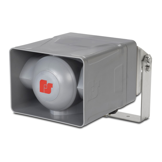
Specifications The following is a picture of the DSA1 Speaker with standard wall-mount bracket. Figure 1 Front and Back of DSA1 Speaker Specifications Table 1 Electrical Operating Voltage 25 V or 70 V Wire size for connectors 12 to 18 AWG... -
Page 10: Installation
The mounting surface must be capable of supporting the weight of the speaker. Wall Mounting The DSA1 Speaker comes standard with a bracket for vertical wall or pole mount with optional pole accessories. The standard mount can be flipped to allow ceiling mount. -
Page 11: Figure 2 Bracket Attached To Speaker
Installation Figure 2 Bracket attached to speaker 1/2" NPT Sealed from the factory 1/4-20 x 5/8" screws (6) Note the orientation of this curved slot with respect to the “FS” on the side of the housing. 3/8-16 x 1" bolts (4) Figure 3 Width and height of bracket 2.00 in 1.44 in... -
Page 12: Figure 4 Depth And Height With Bracket
Installation Figure 4 Depth and height with bracket 6.68 in 2.53 in 10.09 in 2.00 in 12.87 in Figure 5 Top view of speaker 1/2" NPT Sealed from the factory 12.87 in 10.09 in 8.90 in DSA1 Speaker... -
Page 13: Figure 6 Bottom View Of Speaker
Installation Figure 6 Bottom view of speaker 3/4" NPT Sealed from the factory 3/4" NPT 3/4" NPT* *DSA1 Speaker includes a Threaded Plug kit. Figure 7 Ceiling mount Description, Specifications, and Installation Manual... -
Page 14: Pole Mounting
Installation Pole Mounting The DSA1 comes standard with a bracket for vertical wall or ceiling mount. The optional I-IP100-PMW kit or I-IP100-PM kit is required for pole mounting. Large Pole Mounting (6 in diameter or larger) Use the following procedure if mounting the speaker with the optional I-IP100-PMW bracket: 1. -
Page 15: Small Pole Mounting (2-3/8 In Or 4-1/2 In Diameter Poles)
Installation Small Pole Mounting (2-3/8 in or 4-1/2 in diameter poles) Use the following procedure if mounting the speaker with the optional I-IP100-PM bracket: 1. Find suitable location to mount speaker. Use industry or company preferred practices when mounting hardware to poles or other structures. 2. -
Page 16: Mounting With Omni Direction Bracket (2-3/8 In Diameter Pole)
Small Pole Mount section with the omni bracket mounted at a distance of 2.0 inches from the speaker. 1. Identify location for bracket. 2. Attach bracket using supplied U-bolts and hardware. Figure 10 Bracket I-IP100-OMNI 2.0 in Omni Bracket DSA1 Speaker... -
Page 17: Mounting Without Bracket
Installation Mounting without Bracket You can mount the speaker directly to the mounting surface without the bracket. Use installer-supplied 1/4-20 fasteners that are suitable for the mounting surface. Use Figure 10 for the hole center dimensions. Figure 11 Surface mount hole center dimensions 7.39 6.00 3.00... -
Page 18: Wiring The Speaker
3. Use the LINE OUT terminals to connect to an additional speaker or an end-of-line resistor, if required. Speakers in close proximity must be connected in phase. Figure 13 Wiring the Speaker Drawing COM 25V 70V COM 25V 70V LINE IN LINE OUT LINE IN LINE OUT DSA1 Speaker... -
Page 19: Tapping The Speaker
1. Verify that the cover gasket is in the groove around the perimeter of the rear cover. 2. If the front of the unit was removed, lift the front of the DSA1 to allow the hinge pin to be installed, align the front unit with the rear cover and attach the hinge pin with retaining clip. - Page 20 2645 Federal Signal Drive University Park, Illinois 60484-3617 www.fedsig.com Customer Support 800-548-7229 • +1 708 534-3400 Technical Support 800-524-3021 • +1 708 534-3400...
Need help?
Do you have a question about the DSA1 and is the answer not in the manual?
Questions and answers