Advertisement
Quick Links
Advertisement

Related Manuals for Linak LA25


Summary of Contents for Linak LA25
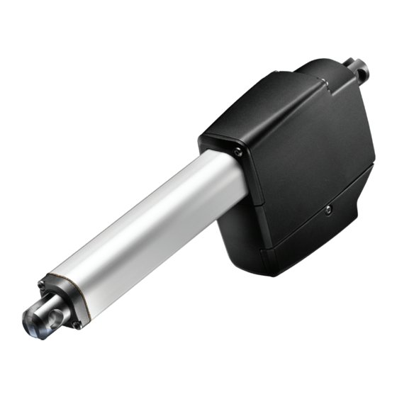
- Page 1 Actuator LA25 IO-Link Quick start guide - Version 1.1 LINAK.COM/TECHLINE...
-
Page 2: Connection Diagram
IO Link 25XXXXXXXXXXAB1X=XXXXXXXXXXXXX (motor +) BROWN M12 connector The LA25 with IO-Link and M12 connector is a (motor -) plug-and-play solution. BLUE If flying leads is the preferred option, please be aware that the LINAK cable colours differ from the IO-Link standard. - Page 3 F O R M O U N T I N G I N S T R U C T I O N S A N D G U I D A N C E I N U S A G E , P L E A S E S E E T H E R E L E V A N T U S E R M A N U A L S 2019 © LINAK A/S...
- Page 4 PD - Process data Process data includes both input and output data and these are cyclically exchanged between the IO-Link master and the actuator LA25. The table below provides an overview of the input and output data: PD - Input...
- Page 5 On the IO-Link master, there are standard IO-Link parameters available such as e.g. Product ID and firmware revi- sion. There are also LINAK specific parameters available. These include configuration of the beaviour in outwards and inwards direction and historic usage data used for diagnostics:...
- Page 6 Checklist - First time installation To guide you through the process of integrating the first LA25 IO-Link in your system, here is a checklist with the most important steps to consider: Configure the IO-Link master to “Type B / Class B”...
-
Page 7: Faqs - Troubleshooting
Why do I get feedback (data) but the actuator is unable to run? The LA25 is designed with a split supply PCB. This means, that an IO-Link master can receive data from the actuator, despite not supplying 24 VDC to the motor itself from a power supply. -
Page 8: Declaration Of Conformity
Declaration of Conformity F O R M O U N T I N G I N S T R U C T I O N S A N D G U I D A N C E I N U S A G E , P L E A S E S E E T H E R E L E V A N T U S E R M A N U A L S... - Page 9 While LINAK uses its best efforts to fulfil orders, LINAK cannot, for the same reasons as mentioned above, guarantee the availability of any particular product. Therefore, LINAK reserves the right to discontinue the sale of any product displayed on its website or listed in its catalogues or other written material drawn up by LINAK.
Need help?
Do you have a question about the LA25 and is the answer not in the manual?
Questions and answers