Linak LA12 User Manual
Hide thumbs
Also See for LA12:
- User manual (39 pages) ,
- Connection diagram (4 pages) ,
- Brochure (16 pages)
Table of Contents
Advertisement
Advertisement
Table of Contents
Troubleshooting

Related Manuals for Linak LA12


Summary of Contents for Linak LA12
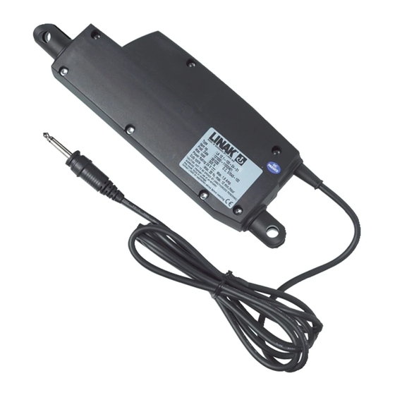
- Page 1 Actuator LA12 User manual LINAK.COM/TECHLINE...
-
Page 2: Table Of Contents
Contents Preface ..............................4 LINAK application policy ........................5 Chapter 1 Safety instructions ..........................6-7 Chapter 2 Mounting guidelines........................... 8-9 Electrical installation: ........................... 10 Recommended fuse ........................10 Actuator without feedback ......................11 Actuator with: Absolute positioning - Mechanical potentiometer feedback ..........12 Absolute positioinng - Analogue feedback ............... - Page 3 Speed and current curves: ....................... 26-27 12V motor ........................... 26 24V motor ........................... 27 Test of conducted and radiated emission (EMC) ................... 28 Label for LA12 ............................ 29 Key to symbols ............................ 29 LA12 Ordering example ........................30 Chapter 5 Maintenance ............................
-
Page 4: Preface
This user manual does not address the end-user, but is intended as a source of information for the manufacturer of the equipment or system only, and it will tell you how to install, use and maintain your LINAK electronics. It is the responsibility of the manufacturer of the end-use product to provide a User Manual where relevant safety information from this manual is passed on to the end-user. -
Page 5: Linak Application Policy
LINAK shall be responsible solely that LINAK products comply with the specifications set out by LINAK and it shall be the responsibility of the LINAK customer to ensure that the specific LINAK product can be used for the application in question. -
Page 6: Safety Instructions
Chapter 1 Safety instructions Please read this safety information carefully: Be aware of the following three symbols throughout the user manual: Warning! Failing to follow these instructions can cause accidents resulting in serious personal injury. Recommendations Failing to follow these instructions can result in the actuator suffering damage or being ruined. Additional information Usage tips or additional information that is important in connection with the use of the actuator. - Page 7 Ensure that the cable cover is mounted correctly. Use 1.5Nm torque. • Ensure that the duty cycle and the usage temperatures for LA12 actuators are respected. • Ensure that the cable cannot be squeezed, pulled or subjected to any other stress.
-
Page 8: Mounting Guidelines
Please pay special attention to the area around the housing where parts can be trapped and cause damage to the application and actuator. In applications with high dynamic forces LINAK recommends not to use the fully extended or retracted position over longer time, as this can damage the endstop system permanently. - Page 9 It is the application manufacturer’s responsibility to incorporate a suitable safety arrangement, which will prevent personal injury from occurring, if the actuator should fail. Warning! LINAK’s actuators are not designed for use within the following fields: • Offshore installations • Explosive environments •...
-
Page 10: Electrical Installation
Electrical installation • To ensure maximum self-locking ability, please be sure that the motor is shorted when stopped. Actuators with integrated controller provide this feature, as long as the actuator is powered. • When using soft stop on a DC-motor, a short peak of higher voltage will be sent back towards the power supply. -
Page 11: Actuator Without Feedback
Actuator without feedback Connection diagram: Fig. 1 : 12xxxx-xxxxxxx0/1 BROWN BLUE Mono Jack plug I/O specifications: Input/Output Specification Comments Description Permanent magnetic DC motor. See connection diagram, fig. 1 above Brown To extend actuator: 12-24VDC (+/-) Connect Brown to positive 12V ±... -
Page 12: Absolute Positioning - Mechanical Potentiometer Feedback
Actuator with absolute positioning - Mechanical potentiometer feedback Connection diagram: Fig. 2 : 12xPxx-xxxxxxx0 BLUE GREEN YELLOW BLACK I/O specifications: Input/Output Specification Comments Description The actuator can be equipped with a mechanical potentiometer that gives an analogue feedback signal when the actuator moves. -
Page 13: Absolute Positioinng - Analogue Feedback
Actuator with absolute positioning - Analogue feedback Connection diagram: Fig. 3 : 12xxxx-xxxxxxx0 BLUE GREEN Signal YELLOW BLACK I/O specifications: Input/Output Specification Comments Description The actuator can be equipped with elec- tronic circuit that gives an analogue feed- back signal when the actuator moves. Signal See connection diagram, fig. -
Page 14: Reed - Relative Positioning 4 Wires
Actuator with Reed - Relative positioning 4 wires Connection diagram: Fig. 4 : 12xxxx-xxxxxxx4 BLUE WHITE REED OUTPUT BLACK I/O specifications: Input/Output Specification Comments Description The actuator can be equipped with a Reed sensor and a spindle magnet that give a relative positioning feedback signal when the actuator moves. -
Page 15: Reed - Relative Positioning 3 Wires
Actuator with Reed - Relative positioning 3 wires Connection diagram: Fig. 5 : 12xRxx-xxxxxxx2/3 BROWN BLACK REED OUTPUT BLUE Stereo Jack plug I/O specifications: Input/Output Specification Comments Description The actuator can be equipped with a Reed sensor and a spindle magnet that give a relative positioning feedback signal when the actuator moves. -
Page 16: Actuator With
Actuator with IC (no EOS out) Connection diagram: Fig. 6 : 12xDxx-xxxxxxx8 BROWN 12/24V DC BLUE BLACK INWARDS OUTWARDS H-Bridge Please be aware that if the power supply is not properly connected, you might damage the actuator! Page 16 of 36... -
Page 17: Ic (No Eos Out)
Actuator with IC (no EOS out) I/O specifications: Input/Output Specification Comments Description Easy to use interface with integrated power electronics (H-bridge). The actuator can also be equipped with electronic circuit that gives an absolute or relative feedback signal. The version with “IC option” cannot be H-Bridge operated with PWM (power supply). -
Page 18: Ic And Endstop Signals
Actuator with IC and endstop signals Connection diagram: Fig. 7 : 12xxxx-xxxxxxx8 BROWN 12/24V DC BLUE BLACK INWARDS OUTWARDS H-Bridge YELLOW GREEN Hall VIOLET FEEDBACK 0-10V WHITE SIGNAL GND/READY Please be aware that if the power supply is not properly connected, you might damage the actuator! Page 18 of 36... - Page 19 Actuator with IC and endstop signals I/O specifications: Input/Output Specification Comments Description Easy to use interface with integrated power electronics (H-bridge). The actuator can also be equipped with electronic circuit that gives an absolute or relative feedback signal. The version with “IC option” cannot be H-Bridge operated with PWM (power supply).
- Page 20 Actuator with IC and endstop signals I/O specifications: Input/Output Specification Comments Violet Mechanical slide potentiometer Max. 100mm stroke 0-10V (Option T) Linearity: ± 20% Slide potentiometer, 10 kohm Minimum lifetime: 15,000 cycles 1 kohm = 0 mm stroke Average lifetime: 40,000 cycles 11 kohm = 100 mm stroke Max.
-
Page 21: Correct Wiring Of Power Gnd And Signal Gnd
Power supply BLUE POWER GND Control connector Hall VIOLET FEEDBACK 0-10V Feedback input WHITE SIGNAL GND 4-20mA LA12 IC actuator Please note that this section only applies for the following feedback options: 0-10V, Hall and PWM. Page 21 of 36... -
Page 22: Chapter 3 Troubleshooting
(if any) Customer fuse burned Check the fuse Cable damaged Please contact your local LINAK supplier For IC only: For IC only: Wrongly connected Please make sure that the power supply... -
Page 23: Troubleshooting
Check the power supply smaller steps Load is higher than specified Reduce the load Actuator cannot Load is higher than specified Reduce the load hold the chosen load For further assistance, please contact your local LINAK supplier. Page 23 of 36... -
Page 24: Specifications
Built-in endstop switches Piston rod and High-strength plastic as standard back fixture: Compatibility: The LA12 IC is compatible with SMPS-T160 (For combination possibilities, please see the User Manual for SMPS-T160) Usage: • Duty cycle at 750N and 2mm pitch is max. 10% Duty cycle at 300N and 4mm pitch is max. -
Page 25: Actuator Dimensions
Actuator dimensions TECHLINE LA12: ® +0.1 10.1 36.3 170.7 19.6 +0.1 10.1 6.1+0.2 +0.2 LA12 Stainless steel 255mm 16.5 Page 25 of 36... -
Page 26: Speed And Current Curves
Speed and current curves - 12V motor The values below are typical values and made with a stable power supply and an ambient temperature of 20˚C. LA12 - 12V Speed v's Thrust 6mm pitch 4mm pitch 2mm pitch Thrust (N) -
Page 27: Motor
Speed and current curves - 24V motor The values below are typical values and made with a stable power supply and an ambient temperature of 20˚C. LA12 - 24V Speed v's Thrust 6mm pitch 4mm pitch 2mm pitch Thrust (N) -
Page 28: Motor
• The actuator has been tested when operating with constant 80%-PWM. • Radiated emission requirements are met. • Conducted emission requirements are met. 2) For systems with LINAK PWM regulation (among other things parallel operation and speed regulation) the following is valid: • Radiated emission requirements are met. -
Page 29: Label For La12
It is important that the operator follows the instructions of the duty cycle; otherwise, a possible overload may result in reduced product life/errors 7. W/O #1234567-0001 The LINAK work order followed by a unique sequential identification number Key to symbols The following symbols are used on the LA12 label:... -
Page 30: La12 Ordering Example
P = Potentiometer max. 100 mm stroke (5 Core) R = Reed switch 2 pulses/spindle revolution, 4 pole magnet 2 or 3 (3 Core) *IC options for LA12: T = Potentiometer 0-10 V/max. 100mm stroke 8 for IC (8 Core) D = None... -
Page 31: Maintenance
LINAK service centre. In order to avoid the risk of malfunction, all actuator repairs must only be carried out by an authorised LINAK Service shop or repairer, as special tools and parts must be used. -
Page 32: Warranty
LINAK service centre. In order to avoid the risk of malfunction, all actuator repairs must only be carried out by an authorised LINAK Service shop or repairer, as special tools and parts must be used. -
Page 33: Declaration Of Conformity
DECLARATION OF CONFORMITY LINAK A/S Smedevænget 8 DK - 6430 Nordborg Hereby declares that Actuator 12xxxx-xxxxxxxx complies with the EMC Directive 2014/30/EU according to following harmonized standards: EN 61000-4-2:2009, EN 61000-4-3:2006+A1+A2, EN 61000-4-4:2012, EN 61000-4-5:2014, EN 61000-4-6:2014, EN 61000-4-8:2010, EN55016-1-2:2014, EN 55016-2-1:2014, EN 55016-2-3:2010+A1, EN 55025:2008... -
Page 34: Declaration Of Incorporation Of Partly Completed Machinery
Linear Actuators LA12, LA14, LA22, LA23, LA25, LA30, LA35, LA36, LA37 comply with the following parts of the Machinery Directive 2006/42/EC, ANNEX I, Essential health and safety requirements relating to the design and construction of machinery: 1.5.1 Electricity supply... - Page 35 Page 35 of 36...
-
Page 36: Addresses
While LINAK uses its best efforts to fulfil orders, LINAK cannot, for the same reasons as mentioned above, guarantee the availability of any particular product. Therefore, LINAK reserves the right to discontinue the sale of any product displayed on its website or listed in its catalogues or other written material drawn up by LINAK.
Need help?
Do you have a question about the LA12 and is the answer not in the manual?
Questions and answers