Table of Contents
Advertisement
Quick Links
Non-Interlock
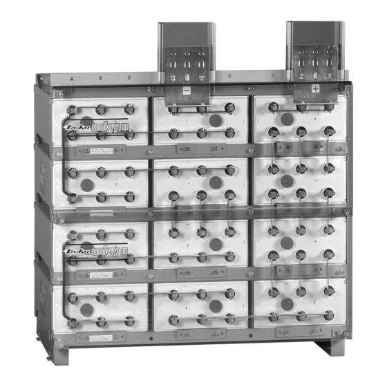
AVR 45, 75, 95 AH
™
Installation and Operation Manual
Battery posts, terminals and related accessories contain lead and lead compounds, chemicals
Proposition
65
known to the State of California to cause cancer and reproductive harm. Batteries also contain
Warning:
other chemicals known to the State of California to cause cancer. WASH HANDS AFTER HANDLING.
E.P.M. Form No. 1112 Revised 12/21
© 2021 by EPM Printed in U.S.A.
Advertisement
Table of Contents

Related Manuals for Deka unigy II SPACESAVER Non-Interlock AVR 45 AH


Summary of Contents for Deka unigy II SPACESAVER Non-Interlock AVR 45 AH
- Page 1 Non-Interlock AVR 45, 75, 95 AH ™ Installation and Operation Manual Battery posts, terminals and related accessories contain lead and lead compounds, chemicals Proposition known to the State of California to cause cancer and reproductive harm. Batteries also contain Warning: other chemicals known to the State of California to cause cancer.
-
Page 2: Table Of Contents
NON-INTERLOCK TABLE OF CONTENTS SAFETY PRECAUTIONS SYSTEM OPERATIONS Protective Equipment ............... b.3 Charge Voltage ................b.19 Procedures ................b.3 Charge Current ................b.19 Temperature Compensation ...........b.19 RECEIVING & STORAGE Cell Voltage ................b.19 Receiving Inspection ..............b.3 Rectifier Ripple Voltage ............b.19 Unpacking ................. b.3 Storage / Refresh .............. -
Page 3: Safety Precautions
SAFETY PRECAUTIONS 10. The below IEEE Standards contain additional information. Other standards may be relevant to your specific application. Although all valve-regulated cells have the electrolyte immobilized IEEE 1184 - Guide for Batteries for UPS Systems within the cell, the electrical hazards associated with batteries IEEE 1187 –... -
Page 4: Installation
Storage / Refresh System Installation Continued 5. Whenever a refresh charge is required, it’s important that all System Shipment batteries to be installed in the same series string receive a charge at the same time to ensure continuity once placed in Battery string will be received per drawing below. - Page 5 4. Anchor holes can be marked and drilled with bases in place. 8. Module connecting hardware is furnished with a dragon tooth Consult Appendix C for anchor hole pattern. All anchor washer in place of a lock washer and flat washer. holes in base are required to be used to meet seismic re- The dragon tooth washer is used to enhance the electrical quirements.
-
Page 6: Safety Shield Bracket Assembly
Safety Shield Bracket Assembly 1. Safety shield brackets are to be installed at the outside corners of every 2 modules starting from the bottom and working towards the top. This is to be repeated for each stack in the battery system. For stacks containing odd number of modules an additional set of safety shield brackets will be required to be installed at the top of the module. -
Page 7: Electrical Connection
2. Safety shield brackets are to be installed at the top of the Electrical Connection module in the same manner as detailed previously. Tighten, do not torque hardware. Connector Assembly 1. The contact surfaces of each individual post on every cell have been cleaned and coated with a thin film of No-Ox-ID “A”... - Page 8 5 to 15 Plate 17 to 27 Plate 29 to 33 Plate...
- Page 9 4. Unigy II battery strings are typically supplied with connector package 1CU requiring one connector per post. 1CU Package Detail 5. High rate applications will require multiple connectors to be used per cell post. A 2CU connector package will require 2 connectors per connection (1 per side), see example below.
- Page 10 6. Some installations require a vertical “C” connector. This 17 to 27 Plate “C” connector is limited to a 2CU connector package. 1. Install “L” connector with vertical bolt as below. Bolt Consult below for proper installation for particular cell type should be installed loosely for future adjustments.
-
Page 11: Terminal Assembly
Terminal Assembly 29 to 33 Plate 1. Install “L” connector with vertical bolt as below. Bolts Top Termination should be installed loosely for future adjustments. Duplicate connection process at both connection points. Consult battery string layout diagram for termination location. 1. - Page 12 3. Install terminal plate to battery posts using 1/4-20 hardware 5. After confirming alignment safety shield bracket hardware (consult battery string layout diagram & parts kit for specific should be tightened, but not torqued. All remaining hardware length). should be torqued. Consult “Hardware Torque Requirements” (pg.
- Page 13 8. Top terminal plates are designed to accept up to 0.50" dia. bolt COMPLETED and use a maximum 1.75" center, 2 hole lug. ASSEMBLY Lug and lug hardware not included. 7. Top terminal assembly will vary by battery plate size. 5 to 15 Plate 17 to 19...
-
Page 14: Side Termination
Side Termination 4. Install side terminal connector to battery posts using 1/4- 20 bolts. Bolts should be installed loosely for future adjustments. Consult battery string layout diagram for termination location. 1. Remove module bolts (3/8-16 x 1.25") from the module where side termination is to be installed. - Page 15 4CU / 6CU CONNECTOR PACKAGE 4CU / 6CU CONNECTOR PACKAGE (double connector) (1/4-20 x 1.25” hardware required) 7. After all parts are installed and alignment is confirmed, safety shield bracket hardware should be tightened, but not torqued. All remaining hardware should be torqued Consult “Hardware 5.
- Page 16 SIX TERMINAL PLATE BRACKET ASSEMBLY 9. Depending on the termination location, side terminal plates may be adjacent to each other. The side terminal bracket attachment is different depending on the number of adjacent terminal plates. SLEEVE SPACER TWO TERMINAL PLATE BRACKET ASSEMBLY SLEEVE SPACER SLEEVE...
- Page 17 10. Side terminal plate is designed to use up to 0.50" dia. bolt and a maximum 1.75" centers, 2 hole lug. Plate is capable of handling 4 runs of cable. Lugs can be positioned on both sides of the terminal plate. Lug and lug hardware not included. Lug Positioning Options b.17...
-
Page 18: Final Assembly Check Procedure
Final Assembly Check Procedure 1. For future identification, individual cells should be numbered in electrical connection sequence, beginning with number one (1) at the positive end of the battery string. NOTE: Following steps are to be followed with battery disconnected from any load or charge source. 2. -
Page 19: Top Protection Shield Installation
Battery Operation Top Protection Shield Installation Battery string operating temperature will affect battery string For side terminal assembly, attach top protective cover to highest capacity and operating life. front shield. Temperatures greater than 77°F (25°C) will reduce the operating For top terminal assembly, cut protective cover to fit between life of the battery. -
Page 20: Acceptance Testing
Acceptance Testing MAINTENANCE Each cell should be at 100% State of Charge prior to Always wear eye protection when working on or near batteries. performing an acceptance test on the battery system. To ensure Keep sparks and open flames away from batteries at all times. the cells are fully charged the following charge schedule should Review Safety Precautions on (pg b.3). -
Page 21: Battery Cleaning
Battery Cleaning c. Unscrew valve ¼ turn using 17mm hex key (pressure will release). Batteries, cabinets, racks, and modules should be cleaned with clean d. Tighten valve immediately and torque to 12-14 in lb with water. If neutralizing is required use a mixture of 1 lb baking soda to 17mm hex key. -
Page 22: Cell Replacement Procedure
8. Pull cell from module onto lifting device. Care should be taken so lifting device does not come in contact with cell posts. Cell Replacement Procedure 1. Cells develop internal pressure. Relieving this pressure from the cell will make it easier to install the cell into the module. Follow the steps of “Cell Removal Procedure”... - Page 23 EPM ORDER NUMBER WILL APPEAR ON THE SHIPPING LABEL ON THE CARTON COVERING EACH PALLET OF CELLS TO ENSURE CONTINUATION OF WARRANTY, SUBMIT FORMS TO: East Penn Mfg. Co, Inc., Reserve Power Division, Product Support & Warranty Dept. (reservepowerwarranty@dekabatteries.com) Form available as an Excel spreadsheet. Consult your EPM or Deka Services Representative b.23...
- Page 24 APPENDIX B Unigy II Space Saver System Acid Volumes & Weights Electrolyte Pure Acid Cell (per cell) (per battery) Battery Weight Volume Weight Weight Type liter AVR45-5 0.37 1.40 4.00 1.81 1.60 0.72 AVR45-7 0.52 1.96 5.60 2.54 2.24 1.02 AVR45-9 0.67 2.52...
-
Page 25: Appendix C - Non-Interlock Base Anchor Hole Pattern
APPENDIX C Non-Interlock Base Anchor Hole Pattern b.25... -
Page 26: Voltage Compensation Chart
APPENDIX D Voltage Compensation Chart Standby (Float) Application Charge Current Limits Non-Interlock AVR45 Series AVR75 Series Refresh / °C Float °F Max. Charge Min. Charge Max. Charge Min. Charge Equalize Cell Type Cell Type Current (A) Current (A)** Current (A) Current (A)** >35 2.230... -
Page 27: Voltage Compensation
APPENDIX E Renewable Energy (Cyclic) Charge Parameters Max. Current Reference Bulk Charge (Amps) Below Chart Absorption (Regulation)Charge Constant Voltage 2.35 - 2.40 vpc Float Charge Constant Voltage 2.24 - 2.26 vpc Equalize Charger Constant Voltage 2.40 - 2.43 vpc Temperature Coefficient 3mV / °C Renewable Energy (Cyclic) Voltage Compensation... - Page 28 APPENDIX F Renewable Energy (Cyclic) Maximum Charge Current AVR45 Series AVR75 Series Max. Charge Max. Charge Cell Type Cell Type Current (A) Current (A) AVR45-5 21.4 AVR75-5 35.5 AVR45-7 32.2 AVR75-7 53.2 AVR45-9 42.9 AVR75-9 70.9 AVR45-11 53.6 AVR75-11 88.7 AVR45-13 AVR75-13 64.3...
- Page 32 e-mail: reservepowersales@dekabatteries.com East Penn Manufacturing Co. Lyon Station, PA 19536-0147 Phone: 610-682-6361 Fax: 610-682-4781 www.dekabatteries.com All data subject to change without notice. No part of this document may be copied or repro- E.P.M. Form No. 1112 12/21 © 2021 by EPM Printed in U.S.A. duced, electronically or mechanically, without written permission from the company.
Need help?
Do you have a question about the unigy II SPACESAVER Non-Interlock AVR 45 AH and is the answer not in the manual?
Questions and answers