Table of Contents
Advertisement
Quick Links
Advertisement
Table of Contents

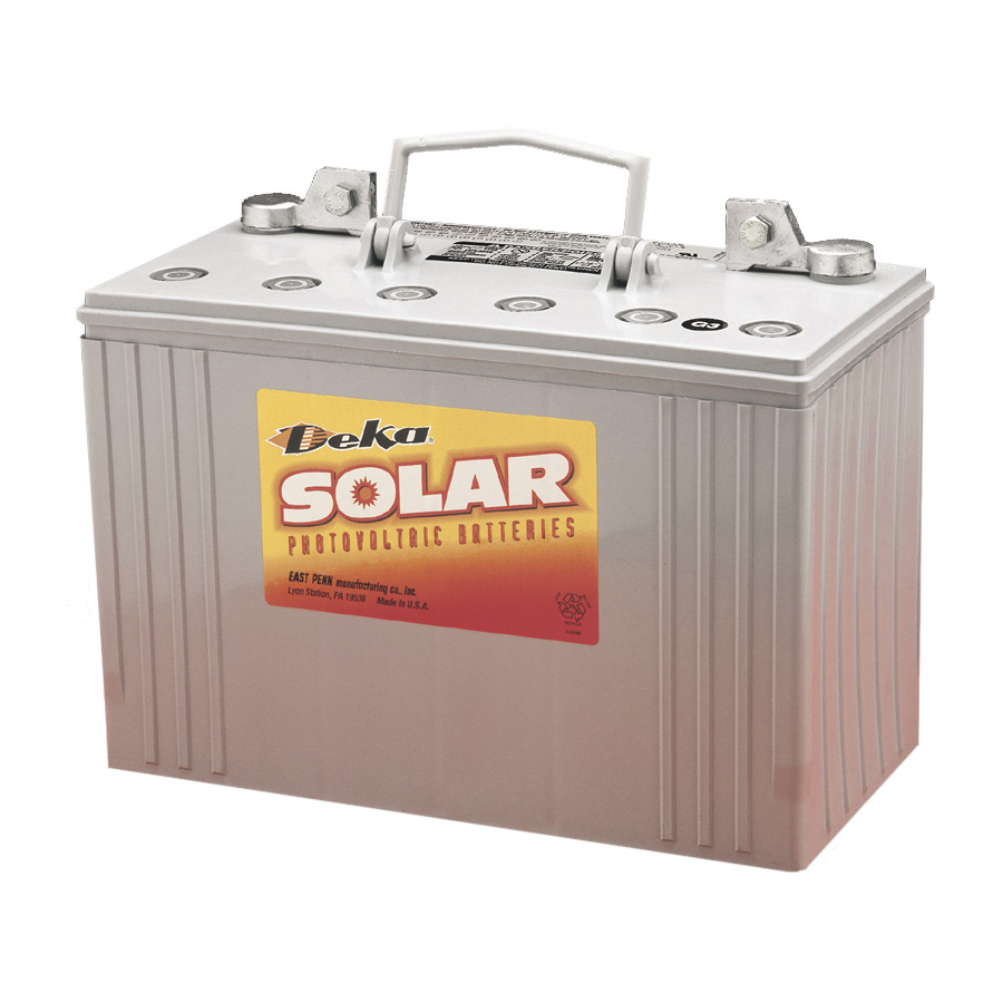
Summary of Contents for Deka SOLAR Monoblock VRLA System
- Page 1 Monoblock VRLA System Installation & Operating Manual...
-
Page 2: Table Of Contents
TABLE OF CONTENTS System Design ..........1 Installation General ............X Battery Operation Grounding ............X Temperature ............1 System Operation Depth of Discharge (DoD) ......1 Charging ............1 Charging ............X Inverter/Charge Controller Settings ....1 Charging Parameters ........X Bulk ............2 Charge Current..........X Absorption..........2 State of Charge ..........X Float ............2 Record Keeping Equalize ............3... -
Page 3: System Design
Renewable Energy applications that depend on battery power as part of the system operation must be at maximum performance at all times. To ensure this high rate of performance is achieved, the battery charging system must be set properly. A battery/battery bank that is undercharged or overcharged will affect the battery system performance &... -
Page 4: Bulk
Bulk Charge Current Verification: ontinued FLOODED Bulk Charge Stage Time Calculation: C20 x 0.44/charge current available Max Time (Hr) = (Ahr x 1.2)/Avg. Current (A) Example: Ahr = Amp hours removed during discharge. Maximum Charge Current 1.2 = Recharge multiplier Battery Rating: 1186 (C20) Avg. -
Page 5: Equalize
Equalize Battery Racking System ontinued ontinued Charge Controller/Inverter charge setting recommendations Adequate space and accessibility for taking individual battery or are detailed in System Operation section of this manual. A cell voltage, hydrometer readings and adding water should be voltage range is provided because of equipment setting considered. -
Page 6: Series/Parallel Wiring
Series/Parallel Wiring Series and parallel wiring of batteries as well as battery to inverter/charge controller wiring should be designed to minimize voltage drop. Wire gauge, wire length as well as interbattery connection layout are all variables in reducing volt- age drop as well as providing battery balance between parallel battery strings. -
Page 7: Safety Precautions
SAFETY PRECAUTIONS 6. Inspect flooring and lifting equipment for functional adequacy. Although all valve-regulated batteries have the electrolyte 7. Adequately secure cell modules, racks, or cabinets to the immobilized within the battery, the electrical hazard associated floor. with batteries still exists. Work performed on these batteries 8. -
Page 8: Grounding
Charging Parameters Grounding When grounding the battery system, proper techniques should Charge Voltage be applied per electrical standards, such as NEC and/or local Bulk Charge: BATTERY ASSEMBLY codes, as well as User Manual of specific application. Current limited to 30% of C20 or 6 times I20. Absorption Charge: (Always wear eye protection.) 12.10V to 14.40V per 12V battery... -
Page 9: State Of Charge
State of Charge Annual Inspection Battery state of charge can be determined by measuring the Depending on the application, some of the following recom- open circuit voltage. Consult the below table. mendations may not apply. State of Charge vs. Open Circuit Voltage* 1. -
Page 10: Glossary
Capacity Testing ontinued End Voltage – The minimum voltage at which a DC system will operate. The test is conducted by discharging a fully charged battery at a specific rate until the battery voltage drops to a predeter¬mined volts per battery, times the number of batter- Flooded –... - Page 11 APPENDIX A Completing all parameters ensures accurate battery sizing. Worksheet to be submitted to sales representative for battery recommendation.
-
Page 12: Appendix B - Example Of Typical 3 Stage Charger
APPENDIX B Example of typical 3 stage charger... -
Page 13: Appendix C - Depth Of Discharge Vs. Freezing
APPENDIX C Depth of Discharge vs. Freezing Point... -
Page 15: Appendix E - Voltage Compensation Chart
APPENDIX E Voltage Compensation Chart ")'*+,-./0&*1(2&3# !"# $%&'(# 4235# 4'65# ≥ ≥ $!%!&# $!%'&# $(%()# !"# *"# $!%!(# $!%'(# $(%(&# *!%&# $!%!'# $!%''# $(%((# *$%(# !&# $!%!+# $!%'+# $(%("# ,*%'# $!%!*# $!%'*# $(%(+# ,+%,# $!%($# $!%+$# $(%(*# ,'%)# &*# $!%(!# $!%+!# $(%"$# ,(%&#... -
Page 16: Charging Current Vs Charging Time Chart
APPENDIX F Charging Current vs Charging Time chart Discharge Voltage Curve... - Page 17 APPENDIX G...
- Page 18 Notes: All data subject to change without notice. No part of this document may be copied or reproduced, www dekabatteries com An East Penn Manufacturing Co. Subsidiary electronically or mechanically, without written permission 1-800-372-9253. www.mkbattery.com from the company. e-mail: sales@mkbattery.com E.P.M.


Need help?
Do you have a question about the SOLAR Monoblock VRLA System and is the answer not in the manual?
Questions and answers