
Related Manuals for LELY Luna


Summary of Contents for LELY Luna
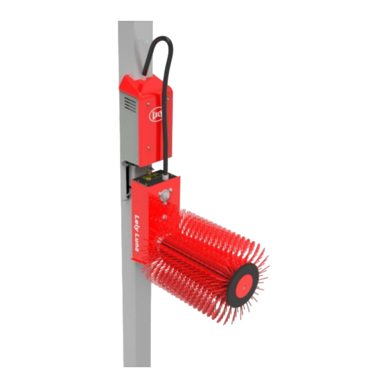
- Page 1 Lely Luna Rotary Cow Brush Installation and Operator Manual EN-US – English Original 5.4101.8538.0 B Lely Industries N.V. www.lely.com...
- Page 2 in n o vato rs in ag ric u ltu re INTENTIONALLY BLANK...
- Page 3 Lely reserves all rights with respect to its trademarks. Any unauthorized use of any Lely-owned trademark or any use of a trademark that is confusingly similar to, or likely to cause confusion with a Lely-owned trademark, would constitute infringement of Lely’s exclusive rights. All rights reserved.
- Page 4 in n o vato rs in ag ric u ltu re INTENTIONALLY BLANK Trademarks, Copyright and Disclaimer...
- Page 5 in n o vato rs in ag ric u ltu re List of included Amendments Issue Date Revision Chapter(s) Remarks (yy/mm) 2018/06 Initial issue. 2018/09 115V machine added. List of included Amendments...
- Page 6 in n o vato rs in ag ric u ltu re INTENTIONALLY BLANK List of included Amendments...
- Page 7 Store this manual in a safe place for future reference. All information in this manual has been compiled with care. Lely shall not be liable for errors or faults in this manual. The recommendations are meant to serve as guidelines. All instructions, pictures and specifications in this manual are based on the latest information that was available at the time of publication.
- Page 8 in n o vato rs in ag ric u ltu re Figure 1. Type and serial number plate (depending on region) We suggest that you complete the table below with the type and serial numbers of your machine. This makes sure that you can easily find the information. Type number Serial number Personnel Requirements...
-
Page 9: Table Of Contents
Table of Contents The Lely Luna Rotary Cow Brush ..............1-1 Intended Use . - Page 10 ................6-1 Switch the Luna On or OFF .
-
Page 11: The Lely Luna Rotary Cow Brush
Intended Use The Luna enables the cows to scratch their head and back. The machine must only be used for short-haired cows older than one year. Long-haired cows can only use the machine if their hair and tail are trimmed regularly. - Page 12 INTENTIONALLY BLANK The Lely Luna Rotary Cow Brush...
-
Page 13: Safety
Safety This chapter contains safety instructions you must obey when you install, use or do maintenance on your Luna. It also explains the safety decals on the Luna. Signal Icons Note the use of the signal words DANGER, WARNING and CAUTION with the safety messages. The signal... -
Page 14: Safety Instructions
Wear protective clothing (safety shoes). • Review safety related requirements with all machine operators frequently (annually). • Contact your nearest Lely service provider if you have any questions. • 2.2.2 Electrical Safety Only an authorized electrician must install the electrical power supply for the machine. -
Page 15: Operation Safety
Always be alert of unexpected movement of the cow. • Keep the machine and its immediate vicinity as clean and as dry as possible. • Contact your nearest Lely service provider if you have any questions. • 2.2.4 Installation Safety Read and understand this manual and all safety signs before you connect power supplies to operate, •... -
Page 16: Safety Decals
in n o vato rs in ag ric u ltu re Safety Decals 2.3.1 Position of the Safety Decals KEY: 1. General safety decal - 2. High voltage decal Safety... -
Page 17: Explanation Of Safety Decals
in n o vato rs in ag ric u ltu re 2.3.2 Explanation of Safety Decals Decal Explanation Warning Read and understand the manual before installing or using this machine (see Position of the Safety Decals on page 2-4). Failure to follow instructions could result in serious injury (see Position of the Safety Decals on page 2-4). -
Page 18: Maintenance Of Safety Decals
Replace safety decals that are missing or that are illegible. • • Safety decals can be purchased from your local Lely service provider. Safety... -
Page 19: Specifications
in n o vato rs in ag ric u ltu re Specifications Dimensions and Weight The dimensions and weight include the bracket but exclude the installation parts and fasteners. • Dimensions: Width: 24 cm (9.45 in). • Height: 116.5 cm (45.87 in). •... - Page 20 in n o vato rs in ag ric u ltu re INTENTIONALLY BLANK Specifications...
-
Page 21: Description And Operation
in n o vato rs in ag ric u ltu re Description and Operation Component Description The machine has the following parts (see figure 2 on page 4-1): Frame. • Cover with box. • Motor housing. • Brush shaft. • Brush. -
Page 22: Operation
in n o vato rs in ag ric u ltu re Operation When the machine is in rest, the machine is in a vertical position. When a cow moves the motor housing, the motor starts to rotate the brush (see figure 3 on page 4-2). Two inductive sensors monitor the movement of the brush and engage the motor. -
Page 23: Cow Hair Conditions
in n o vato rs in ag ric u ltu re The brush has a free rotating axle when unpowered. This helps the cow to easily pull his tail from the brush when its blocked. Make sure cows who use the machine have no loose neck straps, ropes and so on. - Page 24 in n o vato rs in ag ric u ltu re INTENTIONALLY BLANK Description and Operation...
-
Page 25: Installation
Install the wall socket on a minimum height of 2.3 m (90.6 in). Install the machine on a wall or pillar suitable to carry the load exerted by the weight of the machine and the cow. Lely does not recommend to install the machine on a hardboard or plasterboard. -
Page 26: Determination Of Installation Height
Installation of the box (see Install the Box on page 5-17). Installation of the brush (see Install the Brush on page 5-25). Connect the machine to the main electrical supply with the power cable (see Switch the Luna On or OFF on page 6-1). -
Page 27: Installation Of The Frame
Installation Conditions Do not install the machine on a wall or pillar not suitable to carry the load exerted by the weight of the machine and the cow. Lely does not recommend to install the machine on a hardboard or plasterboard. -
Page 28: Install The Frame On The Wall
in n o vato rs in ag ric u ltu re 5.3.2 Install the Frame on the Wall Preparation Unexpected cow movement. Risk of being crushed or trampled. Block the cow traffic. Determine the correct installation height (see Determination of Installation Height on page 5-2). Installation Install the plates (4, 1) on the frame (6) with the bolts (5), washers (2) and nuts (3) (see figure 5 on page 5-5). - Page 29 in n o vato rs in ag ric u ltu re Figure 5. Install the plates Item Qty. Part no. Technical data 5.4101.0289.0 Plate red 9.1048.0007*1 Washer A10,5 DIN 125-St 9.1030.0004*2 Nut M10 DIN985-8 5.4101.0288.0 Plate red 9.1058.0056.5 Coach bolt M10x25 DIN603-8.8 Frame 5.4101.0266Z0 Installation...
-
Page 30: Install The Frame On A Round Pillar
in n o vato rs in ag ric u ltu re Figure 6. Hole pattern KEY: A: 12.6 cm (4,96 in) B: 70.1 cm (27.6 in) C: 12 cm (27.24 in) D: 5.5 cm (2.19 in) E: 3.5 cm (1.38 in) F: 8 cm (3.15 in) G: 31.05 cm (12.25 in) H: 50.6 cm (19.92 in) - Page 31 in n o vato rs in ag ric u ltu re Installation Use a pen to mark the installation height on the pillar (see figure 4 on page 5-3). Install the nuts (1) and washers (3) on the tube clips (2) and turn the nuts (1) to the end of the thread (see figure 7 on page 5-8).
- Page 32 in n o vato rs in ag ric u ltu re Figure 7. Install the nuts and washers on the tube clip Item Part no. Qty. Technical data 9.1029.0005*4 Nut M10 DIN934-8 9.1029.0008*0 Nut M12 DIN934-8 9.1066.0047.25 Tube clip 2" x M10 9.1066.0048.3 Tube clip 2.5"...
- Page 33 in n o vato rs in ag ric u ltu re Figure 8. Install the filling piece on the frame Item Part no. Qty. Technical data 9.1066.0043.5 Filling piece 2" / 2.5", RUK 60, 3 PP 9.1066.0045.0 Filling piece 3" / 4", RUK 88, 9 PP 5.4101.0266Z0 Frame Installation...
- Page 34 in n o vato rs in ag ric u ltu re Figure 9. Install the frame Item Qty. Part no. Technical data 9.1029.0005*4 Nut M10 DIN934-8 9.1029.0008*0 Nut M12 DIN934-8 9.1048.0007*1 Washer A10,5 DIN 125-St 9.1048.0012*6 Washer A13 DIN 125-St Frame 5.4101.0266.0 9.1066.0047.25...
-
Page 35: Install The Frame On A Square Pillar
in n o vato rs in ag ric u ltu re 5.3.4 Install the Frame on a Square Pillar Preparation Unexpected cow movement. Risk of being crushed or trampled. Block the cow traffic. Determine the correct installation height (see Determination of Installation Height on page 5-2). Installation Use a pen to mark the installation height on the pillar (see figure 4 on page 5-3). - Page 36 in n o vato rs in ag ric u ltu re Figure 10. Install the bracket Item Qty. Part no. Technical data 5.4101.0286.0 Bracket (140 mm (5.52 in)) 5.4101.0285.0 Bracket (190 mm (7.48 in)) 9.1058.0047.3 Coach bolt M10x20 DIN603-8.8 9.1048.0007*1 Washer A10,5 DIN 125-St 9.1030.0004*2 Nut M10 DIN985-8...
- Page 37 in n o vato rs in ag ric u ltu re Figure 11. Install the frame Item Qty. Part no. Technical data 5.4101.0286.0 Bracket (140 mm (5.52 in)) 5.4101.0285.0 Bracket (190 mm (7.48 in)) 9.1048.0007*1 Washer A10,5 DIN 125-St 9.1113.0037*1 Bolt M10x55 DIN933-8.8 9.1030.0004*2 Nut M10 DIN985-8...
-
Page 38: Install The Motor Housing
in n o vato rs in ag ric u ltu re Install the Motor Housing Installation Heavy parts. Risk of personal injury. This procedure must be done by two persons. Potential falling object. Risk of personal injury. Always ware safety shoes and stand clear from the machine part during installation. - Page 39 in n o vato rs in ag ric u ltu re Figure 12. Install the motor housing onto the frame Item Qty. Part no. Technical data 5.4101.1500.0 Motor Housing 5.4101.0266Z0 Frame Motor housing shaft Installation 5-15...
- Page 40 in n o vato rs in ag ric u ltu re Figure 13. Make sure the motor housing has no clearance KEY: 1. Screw (2x) A: 0 mm 5-16 Installation...
-
Page 41: Install The Box
in n o vato rs in ag ric u ltu re Figure 14. Install the motor housing Item Qty. Part no. Technical data Screw 9.1048.0041*0 Washer A13 DIN 9021 9.1121.0011.2 Spring-washer A12 DIN127 9.1113.0265.5 M12x25 DIN933–8.8 Install the Box Special Tools •... - Page 42 in n o vato rs in ag ric u ltu re Installation Unexpected cow movement. Risk of being crushed or trampled. Block the cow traffic. Pinch point. Moving parts can crush or cut. Keep hands clear. If you fix the power cable to the wall, make sure there is enough cable length to open the cover.
- Page 43 in n o vato rs in ag ric u ltu re Tighten the power cable connector (1) firmly by hand. Close the box and install the secure clip (1) (see figure 20 on page 5-24). Figure 15. Install the box KEY: 1.
- Page 44 in n o vato rs in ag ric u ltu re Figure 16. Install the grounding cable to the frame Item Part no. Qty. Technical data 9.1029.0002*1 Nut M6 DIN934-8 9.1121.0008.6 Spring-washer A6 DIN127 Grounding cable Frame 5-20 Installation...
- Page 45 in n o vato rs in ag ric u ltu re Figure 17. Install the motor cable KEY: 1. Motor cable connector - 2. Box - 3. Nut - 4. Cable hose Installation 5-21...
- Page 46 in n o vato rs in ag ric u ltu re Figure 18. Connect the inductive sensor cable connector to the box KEY: 1. Frame - 2. Inductive sensor cable connector - 3. Box 5-22 Installation...
- Page 47 in n o vato rs in ag ric u ltu re Figure 19. Install the power cable (230V version) KEY: 1. Power cable connector - 2. Strain relief - 3. Cover - 4. Box Installation 5-23...
-
Page 48: Install The Junction Box (Usa/Canada 115V)
in n o vato rs in ag ric u ltu re Figure 20. Install the secure clip KEY: 1. Secure clip Install the Junction Box (USA/Canada 115V) The connection of the machine to the power network must be made by a certified electrician. -
Page 49: Install The Brush
in n o vato rs in ag ric u ltu re Close the box and install the secure clip (see figure 20 on page 5-24). Figure 21. Install the junction box and power cable (115V version) Item Qty. Part no. Technical data 5.4101.1590.0a Junction box... - Page 50 in n o vato rs in ag ric u ltu re Installation Unexpected cow movement. Risk of being crushed or trampled. Block the cow traffic. Pinch point. Moving parts can crush or cut. Keep hands clear. Install the brush (1) (see figure 22 on page 5-27). Apply loctite 243 to the bolt (4).
- Page 51 in n o vato rs in ag ric u ltu re Figure 22. Install the brush Item Qty. Part no. Technical data 5.4101.0290.0 Brush 5.4101.0522.0 Buffer washer 5.4101.0523.0 Washer 5.4101.1505.0 Bolt M8x20 Installation 5-27...
- Page 52 in n o vato rs in ag ric u ltu re INTENTIONALLY BLANK 5-28 Installation...
-
Page 53: Operating Instructions
Operating Instructions Switch the Luna On or OFF Rotating parts. Risk of personal injury. Rotating parts can crush or cut. Disconnect the machine from the power supply. Moving parts. - Page 54 in n o vato rs in ag ric u ltu re INTENTIONALLY BLANK Operating Instructions...
-
Page 55: Maintenance
in n o vato rs in ag ric u ltu re Maintenance Weekly Maintenance Electric shock. Risk of severe injury or death. Do not use a high pressure cleaner to clean the machine. Moving parts. Risk of personal injury. Moving parts can crush or cut. Disconnect the machine from the power supply and make sure the machine does not move. -
Page 56: Replace The Brush
in n o vato rs in ag ric u ltu re Figure 23. Clean the ventilation openings Replace the Brush Special tools Torque tool. • Preparation Unexpected cow movement. Risk of being crushed or trampled. Block the cow traffic. Block the cow traffic. Disconnect the machine from the power supply. - Page 57 in n o vato rs in ag ric u ltu re Remove the bolt (4), washer (3) and buffer washer (2) (see figure 22 on page 5-27). Remove the brush (1). Examine the brush (1). If necessary: Clean the brush with water. •...
- Page 58 in n o vato rs in ag ric u ltu re INTENTIONALLY BLANK Maintenance...
-
Page 59: M12 Connectors
in n o vato rs in ag ric u ltu re M12 Connectors M12 Torque Tool The speedcon M12 connectors are installed by hand and then tightened to a defined force with the aid of a torque tool (see figure 24 on page 8-1). Figure 24. - Page 60 in n o vato rs in ag ric u ltu re Do not use pliers to tighten or loosen the M12 connectors. Connect To connect the M12 connectors: Align the markings (1 and 2) of the M12 connector (see figure 25 on page 8-2). Figure 25.
- Page 61 in n o vato rs in ag ric u ltu re Put the bit (3) of the M12 torque tool on the connector (2) (see figure 26 on page 8-3). Figure 26. Connect the M12 connector KEY: 1. Torque screwdriver - 2. Connector - 3. M12 torque bit Turn the torque screwdriver clockwise until you hear a clicking sound.
-
Page 62: Bending Risk M12 Cables
in n o vato rs in ag ric u ltu re Bending Risk M12 Cables Ensure a sufficient bending radius. This is important because a greater bending radius will better absorb energy that results from cable movement. In fixed installations (see figure 27 on page 8-4), the minimum bending radius is 5 times the diameter. For flexible/moveable installations (see figure 28 on page 8-5) a minimum of 10 times the diameter is recommended. -
Page 63: Examine And/Or Replace The Seal Of The Female M12 Connector
in n o vato rs in ag ric u ltu re Figure 28. Flexible/moveable installation KEY: 1. R = Minimum radius A sufficient cable loop at the connection point can prevent the cable jacket and inner conductors from stress and premature wear. Examine and/or replace the Seal of the female M12 Connector The seal of the female M12 connector must be clean to guarantee the IP65 class. - Page 64 in n o vato rs in ag ric u ltu re Visually inspect the seal (1) (see figure 29 on page 8-6) on wear and tear. Figure 29. M12 connectors KEY: 1. Seal - 2. M12 connector angled - 3. M12 connector straight Examine and remove dust from the M12 connector .
- Page 65 in n o vato rs in ag ric u ltu re Replacement Use an O-ring picker (2) (see figure 30 on page 8-7) to remove the seal (1). Figure 30. Replace M12 seal KEY: 1. Seal - 2. O-ring picker - 3. M12 connector Place a new seal in the M12 connector.
- Page 66 in n o vato rs in ag ric u ltu re INTENTIONALLY BLANK M12 Connectors...
-
Page 67: Troubleshooting
• cable. Inverter error. • • Replace or fasten the sensor. If the problem remains, call • your local Lely service provider. The brush does not switch Examine LED activation lights • direction. on sensor Disconnect the power cable •... - Page 68 The machine makes an unusual Disconnect the power cable • noise. from the main electrical supply. • Call your local Lely service provider. Brush runs over the back of the Motor is installed in the Switch the inductive sensors • •...
-
Page 69: Troubleshooting Flowchart
in n o vato rs in ag ric u ltu re Troubleshooting Flowchart Troubleshooting... - Page 70 in n o vato rs in ag ric u ltu re INTENTIONALLY BLANK Troubleshooting...
-
Page 71: Diagrams
in n o vato rs in ag ric u ltu re Diagrams 10.1 Dimensions Figure 31. Dimensions KEY: A: 25.1 cm (9.88 in) B: 66.3 cm (26.10 in) C: 18.6 cm (7.32 in) D: 17.4 cm (6.85 in) E: 116.5 cm (45.87 in) F: 50 cm (19.68 in) G: 56 cm (22.05 in) H: 24 cm (9.45 in) - Page 72 in n o vato rs in ag ric u ltu re INTENTIONALLY BLANK 10-2 Diagrams...
-
Page 73: 11 Disposal
All lubricants and fluids must be disposed in compliance with the local rules and regulations. Contact your local authority or local Lely service provider for further details. Disposal 11-1... - Page 74 in n o vato rs in ag ric u ltu re INTENTIONALLY BLANK 11-2 Disposal...
-
Page 75: 12 Weee
WEEE directive, require special reuse and recycling processing. For this reason, Lely Industries N.V. has arranged that this product can be recycled at the local recycling/ disposal companies to collect and recycle this product at no cost to you. - Page 76 in n o vato rs in ag ric u ltu re INTENTIONALLY BLANK 12-2 WEEE...
-
Page 77: 13 Ec Declaration Of Conformity
in n o vato rs in ag ric u ltu re 13 EC Declaration of Conformity EC Declaration of Conformity 13-1... - Page 78 in n o vato rs in ag ric u ltu re INTENTIONALLY BLANK 13-2 EC Declaration of Conformity...
- Page 80 Lely Industries N.V. CornelisFvanFderFLelylaanF1 NL-3147FPB FMaassluis Tel +31F(0)88F-F12F28F221 Fax +31F(0)88F-F12F28F222 www.lely.com...
Need help?
Do you have a question about the Luna and is the answer not in the manual?
Questions and answers