Table of Contents
Advertisement
Quick Links
Advertisement
Table of Contents

Related Manuals for CESVA SC420


Summary of Contents for CESVA SC420
- Page 1 SC420 Sound Level Meter Spectrum Analyser USER MANUAL M_SC420_v0016_20171215_EN...
- Page 3 Since its beginnings in Barcelona in 1969, has been devoted to manufacturing sound equipment and instrumentation through research, development and innovation, and by registering its own patents. We belong to national and international committees for the establishment and revision of standards and regulations. has a fast and efficient distribution network in over 40 countries around the world.
-
Page 4: Table Of Contents
Contents 1. What does this manual cover? 2. Equipment and literature 3. General device description 3.1 SC420 sound level meter spectrum analyser 3.2 Main features of the SC420 3.3 Device components 4. Inputs and outputs 4.1 SC420 inputs and outputs 4.2 Communications inputs and outputs... - Page 5 9. Switching the device on and off 9.1 Switching the device on 9.1.1 Initial SC420 self-check 9.2 Turning the device off 9.3 Switching the light on and off 10. Checking the device 10.1 Checking the SC420 11. Measuring and recording 11.1 Prior steps...
- Page 6 13.6.1 Octave (1/1) and third octave (1/3) band reverberation time (integrated impulse response method) mode functions 13.6.2 Taking a measurement in octave (1/1) and third octave (1/3) band reverberation time (integrated impulse response method) modes 13.6.3 Octave (1/1) and third octave (1/3) band reverberation time (integrated impulse response method) mode screens 13.7 Occupational noise mode (OPTIONAL)
- Page 7 16.1 Saving a final result 16.2 Making a recording 16.2.1 Types of recording 16.3 Structure of a register 16.4 Viewing and deleting registers 16.4.1 Viewing registers 16.4.2 Deleting registers 16.5 Deleting the card memory 17. Using the inputs and outputs 17.1 Digital inputs and outputs and AC output 17.1.1 AC Output 17.1.2 Digital input...
- Page 8 19.5.2 Measurement range (octave band spectrum analyser)144 19.5.3 Measurement range (third octave spectrum analyser)145 19.6 REVERBERATION TIME 19.6.1 Measuring the decay curve and impulse response 146 19.6.2 Calculating the decay curve from the impulse response 19.6.3 Estimating the slope of the decay curve 19.6.4 Reverberation time measurement lower limit 19.6.5 Quality indicators 19.6.6 Lower limit for reliable results obtained through a filter...
- Page 9 23.1.1 Sound level meter mode functions 23.1.2 1/1 spectrum analyser mode functions 23.1.3 1/3 Spectrum analyser mode functions 23.1.4 Octave (1/1) and third octave (1/3) band reverberation time mode functions 23.1.5 Occupational noise mode functions 23.1.6 FFT analyser mode functions 23.2 Function description 23.2.1 Sound pressure level with Fast and Slow time weightings...
-
Page 10: What Does This Manual Cover
What does this manual cover? 1. What does this manual cover? This manual contains all the information you will need to get the most out of the device you have just purchased. This information is divided into 7 sections: The first section has chapters on the main features of the device and its physical components (chapters 3, 4, 5, 6, 7 and 8). -
Page 11: Equipment And Literature
2. Equipment and literature The first step is to check that all the equipment and literature supplied with the device is there: Material: SC420 sound level meter PV009 windscreen Two AA size 1.5 V alkaline batteries (LR6) ... -
Page 12: General Device Description
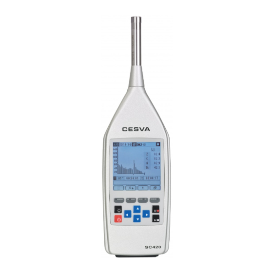
3.1 SC420 sound level meter spectrum analyser The SC420 is more than a sound measuring instrument — it is the ideal tool for the noise professional thanks to its high capacity, versatility and ease of use. The SC420 is a sound level meter that meets the specifications of IEC 61672... -
Page 13: Main Features Of The Sc420
Analysis quality audio recording module When used with the appropriate modules, the SC420 is a sound level meter that you can use to take any kind of measurement: measurements of acoustic insulation and reverberation time in buildings, measurement of environmental parameters (tonal, impulsive and low frequency components), analysis of industrial noise produced by machinery, exposure noise evaluations, etc. - Page 14 (see 14.1). The SC420's screen can be read clearly and precisely in full daylight; it can also be illuminated at the touch of a button, allowing the user to work in low-light conditions as well.
- Page 15 RS-232 serial communication port (see 17). LOG OF CHANGES: Saved in its memory, the SC420 has a log of the last five modifications of changes to date and time and adjustment of sensitivity, with the date and time when they were carried out.
-
Page 16: Device Components
This is protected by the protective cone. Sound level meter LEMO-type connector · LEMO-type female connector for the sound level meter of the SC420. This is protected by the protective cone. Protective cone · Cone that covers the female sound level meter and the male preamplifier LEMO connectors to protect them. - Page 17 19 20 21 Chapter 3 General description of the device...
-
Page 18: Inputs And Outputs
It describes how to identify and configure them, and how to extract data and signals from them. The SC420's inputs and outputs are on the bottom of the device, protected by a removable protective cover. To access them, lift the cover, remembering to put it back once you have finished. -
Page 19: Communications Inputs And Outputs
CONFIGURATION menu (see 15.3.7). 4.4 Digital inputs and outputs The SC420 has a digital input and a digital output. To work with them, use the CN420 cable, inserting the cable's male multi-connector into the female SC420 multi-connector. You will find them on connectors DIGITAL I and DIGITAL O respectively, at the opposite end of the CN420 cable. - Page 20 The digital input can start and stop a data recording depending on its state. The START AUTOMATIC MEASUREMENT STOP AUTOMATIC MEASUREMENT options should be activated and configured with the DIGITAL INPUT option (see 17.1.2). This input can also be used to insert markers while recording data (see 14.3).
-
Page 21: Keypad
These are the keys associated with the main actions, because of their importance and the need to access them at any moment. FUNCTION Key to switch the SC420 on and off. The sound level meter cannot be POWER switched off when a measurement or recording is in progress... - Page 22 SELECTOR KEYS (JOYSTICK): The selector keys (joystick) enable navigation through the menu structure of the SC420 and speed up configuration of parameters and options as well as the change between the different measurement modes. FUNCTION...
-
Page 23: Screen
6. Screen This chapter describes the features of the screen and the information it displays. The SC420 has a 3.2" backlit screen that can display both graphic and numerical data. The SC420's screen is divided into 5 areas; the information that appears on each of these is presented below. - Page 24 UNITS: When measuring or displaying records, this indicates the units of the functions shown in the work area. INDICATORS: The indicators provide continuous information on various aspects of the SC420. INDICATOR INFORMATION Battery power and status (see 7.1) USB or A300 feeder power (see 7.1) Screen light permanently light (see 9.3)
-
Page 25: Work Area
TK200 Outdoor kit correction (see 15.3.5) Automatic measurement start scheduled (see 15.3.3) Automatic recording start scheduled (see 15.3.3) Automatic measurement/recording end scheduled (see 15.3.3) STATUS: Displays the current measurement status of the SC420. INDICATOR SITUATION Stopped Measurement in progress Recording in progress... -
Page 26: Memory Area
The timing area shows the following information: The integration time scheduled for the current mode (T) The integration time elapsed The measurement time elapsed (t) 6.4 Memory area This area is only visible if there is a memory card inserted in the slot and if it is in a measurement mode, both during a measurement and when displaying a record. -
Page 27: Power
Power 7. Power Before turning the SC420 on, the first thing to do is connect it to a power supply. This chapter describes the different ways of powering your device, as well as the configuration options that affect the power supply. -
Page 28: Power Via Usb
When using an external power supply (USB or mains feeder) it is advisable to fit new batteries (see 7.3). If the SC420 is not be used for some time, remove the batteries from the SC420 to prevent damage caused by battery leakage. ... - Page 29 However, it is advisable to disable this option ( ) for all other cases. Therefore, when an external power supply failure occurs during a recording, the device switches to battery power and continues with the measurement until it is manually stopped, the batteries run out or the mains power returns. To activate and deactivate this option, please see 15.3.2.
-
Page 30: Assembling And Dismantling The Device
8. Assembling and dismantling the device This chapter explains how to fit the microphone and the preamplifier to the SC420, as well as all the accessories that can be used for the microphone: the windscreen, extension cable and outdoor kit. -
Page 31: Extension Cable
The SC420 microphone and preamplifier are removable. This allows the microphone to be moved away from the sound level meter and user. Therefore, the SC420 can be operated far from the point of measurement to avoid possible interference. To do this, you need to use one of the following extension cables: CN003 (3 metres), CN010 (10 metres) or CN030 (30 metres). -
Page 32: Connecting The Extension Cable
8.2.2 Connecting the extension cable First, remove the preamplifier from the sound level meter. Pass the protective cone through the extension cable's male LEMO connector (the narrow part first). Insert the extension cable's male LEMO connector into the sound level meter's female LEMO connector until you hear them click perfectly into place. -
Page 33: Outdoor Kit
In the case of using the outdoor kit, activate the respective correction on the SC420 (see 15.3.5). The TK200 requires maintenance: please consult the instruction manual. NOTE: The TK200 outdoor kit is an optional accessory and is not included in the normal operating mode. -
Page 34: Switching The Device On And Off
After a few seconds, the screen of the last measurement mode used will appear. If it is the first time you have used the SC420 or the last time you used it was not in a measurement mode, the main menu will appear. -
Page 35: Initial Sc420 Self-Check
9.1.1 Initial SC420 self-check Should any error be detected during the SC420 initial self-check, an alert screen will be displayed. A description of each alert screen is given below, along with instructions for how to proceed should it appear: SCREEN... -
Page 36: Turning The Device Off
To turn off the SC420, check that no measurement is in progress and press NOTE: Turning off the SC420 may take a few seconds. During this time, the hourglass symbol will appear on the screen to indicate that all the data is being saved. -
Page 37: Checking The Device
CB006 model and follow these steps: Insert the SC420 into the calibrator introducing the microphone into the cavity of the calibrator. Make sure the microphone reaches the bottom of the cavity and is parallel to the calibrator axis (see figure). This may require a little effort since the sound level meter must fit exactly into the calibrator. - Page 38 (FAST) L . The frequency weighting A makes no difference since calibration takes place at 1 kHz. Start measuring with the SC420 in numerical sound level meter mode (see 11.2) Check that the function value on the screen (L or L ) coincides with the value of 94.0 dB corrected with the corresponding corrections (normally 93.9 dB).
-
Page 39: Measuring And Recording
However, with a recording, as the parameters are being measured, the data are also saved in the memory of the SC420. Thus, if the device is turned off, the data are preserved. -
Page 40: Taking A Measurement
NOTE: If it is a recording in sound level meter mode, spectrum analyser in octave bands mode or spectrum analyser in third octave bands mode, the frequency and the functions that the SC420 will store the while recording will appear on screen for 3 seconds, before recording starts. -
Page 41: Overload Indicator
, audio recordings can be made (see 14.5) and while it is in , the Backerase function can be used (see 14.2). The SC420 displays the following icon if it could not make a recording on the microSD card: 11.4 Overload indicator The SC420 is equipped with an overload indicator for each function. -
Page 42: Under-Range Indicator
11.5 Under-range indicator The SC420 is equipped with an under-range indicator for each function. If the value displayed on-screen is under the lower limit of the range of linearity, the indicator will appear in front of the value of the function affected. This indicator only appears while this condition remains. -
Page 43: Menu
Select the measurement mode Record voice comments (see 14.4) 12.1 Accessing the menu Once the SC420 is switched on, ensure there is no measurement in progress and press . The main menu screen is displayed automatically. INDICATOR AREA... -
Page 44: Menu Areas
MENU AREA: Shows the options available on the current menu screen (indicated in the map area) of the SC420. MODE AREA: Shows the measurement modes available on the SC420 and identifies the current mode with a dot. Only available on the main menu screen of the SC420. -
Page 45: Measurement Modes
OPTIONAL audio recording mode for reanalysis To identify which mode the SC420 is in at any moment, simply look at the indicator in the top left-hand corner of the screen, in the indicator area. To select the mode to be worked in, proceed as follows: ... -
Page 46: Sound Level Meter Mode
One of the most notable applications of the SC420 is the measurement of noise levels belonging to noisy activities, urban and road traffic, machinery such as compressors, pumps, etc. Other important applications are the exposure noise... -
Page 47: Sound Level Meter Mode Prior Adjustments
1%, 5%, 10%, 50%, 90%, 95% and 99% *: These functions are measured by the SC420 but are not displayed on screen. The results of these functions can be obtained by making a recording and then downloading it to a PC with Lab (see 17.2) - Page 48 NUMERIC SCREEN: Displays all the functions measured in numeric form. Pressing changes the function frequency weighting. Pressing changes the functions displayed, as below: Pressing takes you to the time history graphic screen. TIME HISTORY GRAPHIC SCREEN: Shows the time history and the value of the F1, F2 and F3 functions. Provides a graphic representation of the last 60 values measured.
- Page 49 Pressing takes you to the advanced screen. ADVANCED SCREEN: Displays special acoustic functions: impulsiveness indicators, indicators of low- frequency spectral content and functions specific to local, national and international standards. Pressing changes the function frequency weighting. Pressing changes the functions displayed, as below: Pressing...
-
Page 50: 1/1 Spectrum Analyser Mode (Optional)
SC420 measures these functions for measurement time (t), the consecutive integration time (T) and every 125 ms ("short" functions). It also measures both global and spectral percentiles. The SC420 has a room background noise evaluation screen: NC (Noise Criterion) and NR (Noise Reduction) curves. -
Page 51: 1/1 Spectrum Analyser Mode Prior Adjustments
*: These functions are measured by the SC420 but are not displayed on screen. The results of these functions can be obtained by making a recording and then downloading it to a PC with Lab (see 17.2). Percentiles are calculated through the L and L functions with class of 0.5 dB. - Page 52 Pressing takes you to the numeric screen. NUMERIC SCREEN: Displays the functions measured in numeric form. Pressing changes the functions displayed, as below: Pressing displays the values of the functions corresponding to the integration time (T). Pressing displays the values corresponding to the measurement time (t).
- Page 53 Pressing takes you to the time history graphic screen. TIME HISTORY GRAPHIC SCREEN: Displays the time history of the LAT function: equivalent level with frequency weighting A and integration time (T). Provides a graphic representation of the last 60 values measured .It also displays the numerical value of the L and L functions.
-
Page 54: 1/3 Spectrum Analyser Mode (Optional)
(t), the consecutive integration time (T) and every 125 ms ("short" functions). At the same time as the spectrum, the SC420 measures the global equivalent level with frequency weighting A, C and Z, together with other sound level meter functions. -
Page 55: Spectrum Analyser Mode 1/3 Functions
*: These functions are measured by the SC420 but are not displayed on screen. The results of these functions can be obtained by making a recording and then downloading it to a PC with Memory Download (see 17.2) - Page 56 The different screens let you view the functions measured (all are measured at the same time). To change screen, you do not need to stop the measurement. All the screens are available for any sound level meter status: In the menus you can configure the integration time (T) (see 15.3.1).
- Page 57 Pressing displays the values of the functions corresponding to the integration time (T). Pressing displays the values corresponding to the measurement time (t). Pressing takes you to the time history graphic screen. TIME HISTORY GRAPHIC SCREEN: Displays the time history of the L function: equivalent level with frequency weighting A and integration time (T).
- Page 58 ADVANCED SCREEN: Displays special acoustic functions: impulsiveness indicators, indicators of low- frequency spectral content and functions specific to local, national and international standards. Pressing changes the functions displayed. Pressing displays the values of the functions corresponding to the integration time (T).
-
Page 59: Octave (1/1) And Third Octave (1/3) Band Reverberation Time (Interrupted Noise Method) Modes (Optional)
To take this measurement, you will need an omni-directional pressure source (FP122) that emits a broadband noise (pink or white noise). With these modes, the SC420 simultaneously measures the value of T the decay curves, together with parameters for the evaluation of quality (C, ξ and B·T). -
Page 60: Taking A Measurement In Octave (1/1) And Third Octave (1/3) Band Reverberation Time (Interrupted Noise Method) Modes
STEP 3: Measuring the decay curve From this point, the SC420 will wait for you to interrupt the noise emission. Stop the noise emission. From this moment, the device measures the decay in the sound pressure level. During this time, it is essential to keep silent so as not to interfere with the measurement. -
Page 61: Screens In The Octave (1/1) And Third Octave (1/3) Band Reverberation Time (Interrupted Noise Method) Modes
13.5.3 Screens in the octave (1/1) and third octave (1/3) band reverberation time (interrupted noise method) modes The octave and third octave band reverberation time (interrupted noise method) modes of the SC420 have the following screens: Numeric ... - Page 62 Pressing takes you to the Noise Level Graphic Screen. and Δ) GRAPHIC SCREEN: NOISE LEVEL (L Displays the spectral graph for the background noise levels (L ) and for the increase in level in relation to the background noise (Δ) in octave or third octave bands, depending on the mode.
- Page 63 Pressing displays the graph corresponding to the T reverberation time. Pressing displays the graph corresponding to the T reverberation time. Pressing takes you to the Quality Numeric Screen. QUALITY (C, ξ and B·T) NUMERIC SCREEN: Displays the values for the curvature parameter (C), the non-linearity parameter (ξ) and the multiplication of the filter bandwidth and the calculated reverberation time (B·T), in octave or third octave bands, depending on the mode.
-
Page 64: Octave (1/1) And Third Octave (1/3) Band Reverberation Time (Integrated Impulse Response Method) Modes (Optional)
(OPTIONAL) NOTE: These modes are optional and can be purchased at the same time as the SC420 or later on. See chapter 22. The octave band reverberation time (integrated impulse response method) mode and the third octave band reverberation time (integrated impulse response method) mode behave similarly;... -
Page 65: Octave (1/1) And Third Octave (1/3) Band Reverberation Time (Integrated Impulse Response Method) Mode Functions
As, in practice, it is impossible to emit a Dirac delta, you can emit short transient sounds similar enough to take the measurements. With these modes, the SC420 simultaneously measures the value of T the decay curves, together with the parameters for the evaluation of quality (C, ξ... - Page 66 STEP 2: Generating the impulsive noise Generate an impulsive noise such as an alarm (or any other non-reverberant source, but that its spectrum is broad enough) to measure the impulse response of the room. From this moment, it is essential to remain silent, so as not to interfere with the measurement.
-
Page 67: Octave (1/1) And Third Octave (1/3) Band Reverberation Time (Integrated Impulse Response Method) Mode Screens
13.6.3 Octave (1/1) and third octave (1/3) band reverberation time (integrated impulse response method) mode screens The octave and third octave band reverberation time (integrated impulse response method) modes of the SC420 have the following screens: Numeric Graphic Noise Level ... - Page 68 Pressing takes you to the reverberation time graphic screen. REVERBERATION TIME (T and T ) GRAPHIC SCREEN: Displays the spectral graph for T and T in octave or third octave bands, depending on the mode. It also displays the numeric value for T , corresponding to the band selected in the graph (vertical cursor) together with its indicator, if applicable (see 13.6.2).
- Page 69 If B·T is less than or equal to 16, as the decay curve is considered to be influenced by the filter. Where the value of B·T is greater than 999, this is represented as: >999. mode displays the values for the 24 third octave bands: to display all of them, use the contextual key.
-
Page 70: Occupational Noise Mode (Optional)
NOTE: This is an optional mode that can be purchased when you buy the SC420 or later on. See chapter 22. The occupational noise mode of the SC420 is designed for the implementation of ISO 9612:2009 on the determination of exposure to noise at work. -
Page 71: Occupational Noise Mode Screens
13.7.3 Occupational noise mode screens The occupational noise mode of the SC420 has the following screens: Numeric Spectral Graphic Time The different screens let you view the functions measured (all are measured at the same time). To change screen, you do not need to stop the measurement. All... - Page 72 the graph (vertical cursor) and the peak level with frequency weighting C for T and t. Pressing displays the values of the functions corresponding to the integration time (T). Pressing displays the values corresponding to the measurement time (t). Pressing activates an automatic zoom of the vertical axis [dB] (see 14.1).
-
Page 73: Fft Frequency Analyser Mode (Optional)
0 Hz to 20 kHz in real time and in the complete dynamic measurement range (without scale change). The FFT analysis has 10,000 effective lines with a resolution of 2 Hz/line. The SC420 measures the equivalent continuous sound pressure level from 1 to 60 seconds with frequency weighting A and Z for each FFT line. -
Page 74: Fft Frequency Analysis Mode Screen
To save the measurement to memory, please see 16.1. 13.8.2 FFT frequency analysis mode screen After finishing the measurement, the SC420 presents all the information on a single screen: FFT GRAPHIC SCREEN: Displays the graph of the equivalent continuous sound pressure level for each FFT line with frequency weighting A and Z. -
Page 75: Audio Recording Mode (Analysis Quality) (Optional)
(OPTIONAL) NOTE: This is an optional mode that can be purchased when you buy the SC420 or later on. See chapter 22. The audio recording mode (analysis quality) enables you to save the audio signal received by the microphone on the memory card. - Page 76 Resolution: 24 bits Sampling frequency: 48 kHz Depending on the dynamic range of the recorded signal, the SC420 can apply a constant gain of 36 dB throughout the recording. This is indicated in the file name: record no.-036dB yyyy-mm-dd hh-mm-ss (file with gain) record no.-000dB yyyy-mm-dd hh-mm-ss (file without gain)
-
Page 77: Advanced Options
14.1 Zoom The graphic representation of the wide dynamic measurement range of the SC420 does not allow the correct appraisal of very stable noise events on the graphic screens for time evaluation and spectral content. A sound event with time variations of just a few decibels will appear represented as a virtually constant event. -
Page 78: Backerase
Pressing takes you back to the normal display (without zoom). 14.2 Backerase While measuring a sound event, especially while measuring background noise, unexpected sounds can appear that do not correspond to the sound event you want to evaluate, and the sound level meter may end up measuring these. In these situations, you might like to use the Backerase option. -
Page 79: Marking
14.3 Marking When measuring a sound event, there are often occurrences that you wish to highlight for easier identification afterwards. To this end, the SC420 is equipped with the marking function. This function is available while making a recording in any mode, except the reverberation time, FFT and audio recording modes. -
Page 80: Voice Comments
It is often necessary to make notes, comments and indications regarding the measurements, environment, etc. For example: comments on measuring points, decisions made on site or spontaneous ideas. To meet this need, the SC420 allows users to record voice comments quickly and easily. -
Page 81: Audio Recording (Listening Quality)
14.5 Audio recording (listening quality) The SC420 allows you to record audio files at the same time as recording acoustic functions , for recognition and subjective evaluation of sound sources (listening quality). Having the audio belonging to the sound pressure levels measured provides additional information that facilitates the evaluation of those levels and decision making. -
Page 82: Automatic Settings: Timers And Triggers
SC420 or if the card is full (see 16.2). 14.6 Automatic settings: Timers and triggers The SC420 has a complete system of automatic settings for starting and stopping measurement and audio recording using automatic timers and triggers activated by exceeding the threshold by time intervals. This extends even further the possibilities for using the SC420 as a stand-alone unit for continuous monitoring of noise, without having to be present to carry out a measurement. -
Page 83: Automatically Stop Measuring/Recording
DEN time interval for more than t seconds before starting the measurement/recording. START SET BY EXTERNAL DIGITAL INPUT The SC420 waits for the external digital input to read 0 before starting the measurement/recording. Once the type of automatic start and its characteristics are set (see 15.3.3),... - Page 84 DEN time interval for more than t seconds before stopping the measurement/recording. STOP SET BY EXTERNAL DIGITAL INPUT The SC420 waits for the external digital input to read 1 before stopping the measurement/recording. REPEAT OPTION: If you have set an automatic start and stop measurement and have activated the repeat option , you can create a permanent measuring loop (see 15.3.3).
-
Page 85: Automatic Audio Recording
Audio recording by external digital input AUDIO RECORDING BY TIME BETWEEN RECORDINGS Firstly, the SC420 starts an audio recording. The SC420 then waits for the programmed waiting time between the start of recordings (hh:mm:ss) to elapse and subsequently starts a new audio recording. This... -
Page 86: Den Intervals
If the NEW EVENT option is activated , once the audio recording ends (5+10 seconds) and the file is saved, the SC420 waits for a new event before making a new audio recording. In other words the sound pressure level ") needs to be lower than the threshold of the current DEN time interval for... -
Page 87: Examples Of Automatic Measurement Settings
= 00:01:00 s = 00:06:00 s RESULT: When pressing , the SC420 waits 1 minute and then starts to measure for 6 minutes. This gives the operator time to press , leave the bedroom (together with the observers) and close the door. They wait 6 minutes and re-enter after the measurement is completed. - Page 88 30 minutes to subjectively assess the origin of the measured levels. Finally, the SC420 stops the recording at 06:00. Should you wish to carry out the same operation the following day, you would only have to programme the...
- Page 89 RESULT: When pressing , the SC420 waits for night-time hours (22:00 to 08:00) to begin before carrying out recordings of the events in excess of 50 dBA for more than 5 seconds. The recording ends when the sound level falls below 50 dB for more than 20 seconds.
- Page 90 23:00:00 RESULT: When pressing , the SC420 makes recordings of the sound events that exceed the limits set down in the environmental regulations (Day and Evening: 70 dBA; and Night: 60 dBA); it also makes a brief audio recording when these exceed the limit by 5 dBA.
- Page 91 SITUATION: Monitoring the noise generated by the tasks of loading and unloading goods onto/from a transport fleet. You need to record noise levels while vehicles are present. To this end, we have installed a presence-detecting sensor that connects to the SC420 [1 No vehicles present; 0 Vehicles present]. PROGRAMMING:...
-
Page 92: Settings And Adjustments
® date and time, sensitivity, Bluetooth wireless communication, etc. 15.1 Accessing the settings sub-menu Once the SC420 is switched on, ensure there is no measurement in progress and press . The menu screen will be displayed automatically. The cursor (highlighted option) will be at the first option in the menu area. Press... -
Page 93: Settings Sub-Menu
AUTOMATISMS functions. Allows you adjust the date and time displayed on the SC420 as well as consult the date/time change log. DATE AND TIME Allows you adjust the sensitivity of the SC420 as well as consult the sensitivity adjustment log. - Page 94 Pressing takes you to the next screen. Using the selector keys, select the mode to be configured and press . Choose the parameter you want to set with the keys, and press to modify the parameter value. If the parameter has several fields, to access them.
-
Page 95: Recording Option
15.3.2 RECORDING option This option sets the periodicity and functions to be stored by the SC420 when making a recording. It also sets how the device behaves when running on USB power and that power source is interrupted. When selecting the recording option,... - Page 96 7.3. When the SC420 is switched off, this option is left in the status set. This means that if it is set to ON, when the SC420 is next switched on, the 'power for environmental monitoring' option will be activated.
-
Page 97: Automatisms Option
15.3.3 AUTOMATISMS option this option parameters automatic start/stop measurement/recording or automatic audio recordings. Selecting it will display the following screen: to choose one of the following options and press DEN TIME INTERVALS Use this option to set the beginning and end for the three time intervals into which the day is divided: . - Page 98 Highlighted and marked as , the option that is currently configured will appear. to select the desired option and press to select the highlighted option. This will appear marked as Press to set the parameters for each option. Use to adjust the parameter value.
- Page 99 For a specific time : enter the value of the stop time in hh:mm:00. For a waiting time : enter the value of the time in hh:mm:00. (If you enter 00:00:00, the device will not recognise this configuration and will maintain the previous values).
-
Page 100: Date And Time Option
15.3.4 DATE AND TIME option This option lets you adjust the date and time of the SC420, which the SC420 uses to reference measurements, recordings and audio recordings. To change the current setting, choose between DATE and TIME and press . - Page 101 When selecting this option, the screen will display the sound pressure level measured by the SC420, along with the following parameters: the sound field correction and TK200 outdoor kit correction, microphone model and sensitivity setting level currently configured. Using , select the parameter to be set. The available options are:...
-
Page 102: Contrast Option
15.3.7 AC OUTPUT option The AC output of the SC420 is directly proportional to the signal obtained at the preamplifier output. This option lets you set the gain for this output: 0 dB or 40 The setting highlighted is the current one; if you wish to change it, use... -
Page 103: Bluetooth Wireless Communication/Printer Option
® For more information on Bluetooth wireless communication, see 17.2.4. For more information on serial communication with a printer, see 17.2.2. When the SC420 switches on, the RS-232 communication is in the state programmed. ® The Bluetooth trademark is the property of Bluetooth SIG, Inc. -
Page 104: Registers And Memory Management
Another option is to take a measurement and then save the results. This record will not contain the time history of the functions, only the final results. The SC420 displays the following icon if it could not make a recording on the microSD card: 16.1 Saving a final result... - Page 105 The SC420 can save a maximum of 64000 final results, regardless of the measurement mode. NOTE: It is only possible to save final results if there is a memory card inserted in the slot, with available space. Below is the breakdown of the functions saved for each measurement mode:...
- Page 106 X: indicates the frequency weighting (A, C and Z). f: indicates the octave band filter with central frequencies of 10, 12.5, 16, 20, 25, 31.5, 40, 50, 63, 80, 100, 125, 160, 200, 250, 315, 400, 500, 630, 800, 1000 (1k), 1250 (1.25k), 1600 (1.6k), 2000 (2k), 2500 (2.5k), 3150 (3.15k), 4000 (4k), 5000 (5k), 6300 (6.3k), 8000 (8k), 10000 (10k), 12500 (12.5k), 16000 (16k) and 20000 (20k) Hz.
-
Page 107: Making A Recording
Use the SOUND LEVEL METER RECORDING option (see 15.3.2) to set the periodicity and data of the time log that the SC420 will save when making a recording in sound level meter mode, in addition to the final results. Seven possibilities are available: These 3 types of recording are conceived for short-duration measurements. - Page 108 T: Programmed XTmax XTmin AF5T integration time XFmax1s XSmax1s XImax1s XFmin1s XSmin1s XImin1s Xpeak1s LXX (125ms): saves all the functions measured every 125 ms: TIME BASE LXX (125ms) SOUND LEVEL METER RECORDING FUNCTIONS: 125ms X125ms Xpeak125ms XF125ms XS125ms XI125ms ...
- Page 109 Use the SPECTRUM ANALYSER RECORDING option (see 15.3.2) to set the periodicity and data of the time log that the SC420 will save when making a recording in 1/1 analyser mode, in addition to the final results. There are 4...
- Page 110 T: Programmed XpeakT integration time These two types of recordings are especially designed to obtain spectral information that is highly detailed in terms of time. These types are perfect for detecting and monitoring noise sources such as vehicle traffic on roads and air traffic at airports.
- Page 111 Use the SPECTRUM ANALYSER RECORDING option (see 15.3.2) to set the periodicity and data of the time log that the SC420 will save when making a recording in 1/3 analyser mode, in addition to the final results. There are 3...
- Page 112 T: Programmed integration time X: indicates the frequency weighting (A, C and Z). n: 1%, 5%, 10%, 50%, 90%, 95% and 99% f: indicates the third octave band filter with central frequencies of 10, 12.5, 16, 20, 25, 31.5, 40, 50, 63, 80, 100, 125, 160, 200, 250, 315, 400, 500, 630, 800, 1000 (1k), 1250 (1.25k), 1600 (1.6k), 2000 (2k), 2500 (2.5k), 3150 (3.15k), 4000 (4k), 5000 (5k), 6300 (6.3k), 8000 (8k), 10000 (10k), 12500 (12.5k), 16000 (16k) and 20000 (20k) Hz.
-
Page 113: Structure Of A Register
Lab application lets you download and delete memory records while the device is measuring. 16.3 Structure of a register Each time you save a final result or make a recording, the SC420 saves a register in memory. Chapter 16 Records and memory management... -
Page 114: Viewing And Deleting Registers
For each register, the register number, the date and time it was recorded and the type of register are displayed. REGISTRER NO. TYPE OF REGISTRER START TIME START DATE INDICATOR TYPE OF REGISTER Sound level meter 1/1 Analyser 1/3 Analyser 1/1 Reverberation time by interrupted noise method 1/3 Reverberation time by interrupted noise method 1/1 Reverberation time by integrated impulse response method... -
Page 115: Viewing Registers
On the left-hand side, you will see the measurement mode of the register being viewed. Pressing takes you to the initial list containing all the registers in the SC420 memory. Chapter 16 Records and memory management... -
Page 116: Deleting Registers
16.5 Deleting the card memory To completely erase the card memory of the SC420, ensure there is no measurement in progress and press . The menu screen will be displayed automatically. -
Page 117: Using The Inputs And Outputs
AC OUTPUT connector of the CN420 cable, when this is connected to the SC420 multi-connector. The AC OUTPUT connector is of the mono female mini jack type. To connect it to any audio device (PC sound card, DAT, digital recorder, headphones, etc.),... -
Page 118: Digital Input
17.1.2 Digital input The digital input of SC420 is an input that lets you start and stop a data recording according to its status. This input can also be used to insert markers while recording data (see 14.3). -
Page 119: Communicating With A Pc, Downloading Data And Communicating With A Printer
SD card readers, for which there are micro SD card to SD card adaptors. The SC420 must be switched off*. Remove the memory card from the SC420 and insert it into the PC's card reader. Using the Lab software, you can now access the SC420 memory card data (see 17.3). -
Page 120: Communications
RS-232 connector of the CN420 cable, when this is connected to the SC420 Multi-connector. The RS-232 connector is of the DB-9 type. To connect it to a computer, use a serial cable such as the CN232. -
Page 121: Usb Communications
CN400 cable. USB communication offers high-speed transfer, ideal for downloading the large quantities of data that the SC420 can store. It can also be used to programme the SC420 and send data in real time. To download records containing audio files, we recommend directly importing them from the memory card. -
Page 122: Pc Software
Manage registers (total or selective deletion). The SC420 lets you download data as it is being recorded. That is, while data are being recorded, they can be downloaded at the same time. It also offers the possibility of deleting some of the registers stored on the card after they have been downloaded. -
Page 123: Accessories
Accessories 18. Accessories The following section describes the accessories supplied with the SC420 and the optional accessories that can be purchased separately. 18.1 Accessories supplied The accessories supplied with the SC420 are the following: MODEL DESCRIPTION CESVALab CESVA Memory Download computer communication software... - Page 124 CN421 Output audio cable TR001 Tripod adaptor PR003 Extendible rod (3 m) NOTE: only guarantees the correct functioning of the device when original accessories are used Any damage caused to the device owing to the use of non-original accessories will not be covered by the warranty.
-
Page 125: Technical Specifications
IEC 61672–1 (2002–05), Class 1, Group Z IEC 61260:1995/A1:2001, Class 1 In accordance with standard IEC 61672-1, the class of the SC420 for response to sound waves incident on the microphone in the reference direction in a free field depends on the microphone used. -
Page 126: Microphones And Preamplifiers
The table below shows the technical features of the microphones and the accessories that attach to them. 19.2.1 Microphone models and their main features As a class 1 device, the SC420 can be used in conjunction with the following brand microphone models: C-130, C140 and C240. - Page 127 4000 8000 12500 16000 CORRECTION OF THE RESPONSE OBTAINED WITH THE B&K ELECTROSTATIC ACTUATOR MODEL UA035 IN A FREE FIELD MICROPHONE C-130 C140 C240 FREQUENCY (Hz) Correction Correction Correction Exact base 10 frequency [dB] [dB] [dB] 63.0957 0.00 0.00 0.00 79.4328 0.00 0.00...
- Page 128 2500 2511.89 0.52 0.49 0.47 2660.73 0.56 0.54 0.52 2818.38 0.63 0.60 0.58 2985.38 0.70 0.67 0.65 3150 3162.28 0.78 0.74 0.71 3349.65 0.86 0.81 0.79 3548.13 0.96 0.89 0.87 3758.37 1.06 0.99 0.97 4000 3981.07 1.19 1.09 1.07 4216.97 1.32 1.21 1.20...
- Page 129 CORRECTION OF THE RESPONSE OBTAINED WITH THE ELECTROSTATIC ACTUATOR IC150 IN A FREE FIELD MICROPHONE C-130 C140 C240 FREQUENCY (Hz) Correction Correction Correction Exact base 10 freq. [dB] [dB] [dB] 63.0957 0.00 0.00 0.00 79.4328 0.00 0.00 0.00 0.00 0.00 0.00 125.893 0.00...
- Page 130 3150 3162.28 0.83 0.71 0.68 3349.65 0.92 0.79 0.76 3548.13 1.02 0.85 0.83 3758.37 1.13 0.95 0.94 4000 3981.07 1.25 1.04 1.04 4216.97 1.38 1.17 1.16 4466.84 1.53 1.30 1.29 4731.51 1.71 1.43 1.42 5000 5011.87 1.89 1.60 1.59 5308.84 2.07 1.77 1.76...
-
Page 131: Frequency Response
19.2.3 Frequency response RESPONSE TO PLANE PROGRESSIVE SOUND WAVES INCIDENT IN THE REFERENCE DIRECTION Correction for the average frequency microphone response for plane progressive sound waves incident in the reference direction. MICROPHONE C-130 C140 C240 FREQUENCY (Hz) Correction Correction Correction Uncertainty Exact base 10 freq. - Page 132 2500 2511.89 -0.08 0.04 -0.02 0.06 2660.73 -0.08 0.03 -0.03 0.06 2818.38 -0.09 0.03 -0.02 0.06 2985.38 -0.08 0.03 -0.03 0.06 3150 3162.28 -0.07 0.02 -0.04 0.06 3349.65 -0.06 0.03 -0.04 0.06 3548.13 -0.05 0.01 -0.06 0.06 3758.37 -0.05 0.01 -0.05 0.06 4000...
- Page 133 Correction for the average effects of the reflections of the sound level meter case and the diffraction around the microphone for plane progressive sound waves incident in the reference direction FREQUENCY (Hz) Correction Uncertainty Exact base 10 freq. [dB] [dB] 63.0957 0.00 0.11...
- Page 134 3548.13 -0.13 0.14 3758.37 -0.02 0.14 4000 3981.07 0.00 0.14 4216.97 -0.13 0.14 4466.84 -0.14 0.14 4731.51 -0.25 0.14 5000 5011.87 -0.08 0.14 5308.84 -0.11 0.14 5623.41 0.02 0.14 5956.62 -0.09 0.14 6300 6309.57 -0.14 0.14 6683.44 -0.10 0.14 7079.46 -0.26 0.14 7498.94...
- Page 135 2.00 1.50 1.00 0.50 0.00 0.50 1.00 1.50 2.00 1000.00 10,000.00 100.00 Frequency (Hz) Correction for the average effects of the PV009 windscreen on the sound level meter frequency response in the absence of wind. FREQUENCY (Hz) PV009 WINDSCREEN Correction (dB) Uncertainty [dB] Exact base 10 freq.
- Page 136 RESPONSE WITH RANDOM INCIDENCE IN A DIFFUSE FIELD Correction for the average frequency response of theSC420 sound level meter, with the sound field correction set to diffuse field, for response with random incidence in a diffuse field. MICROPHONE C-130 C140 C240 FREQUENCY (Hz) Correction Correction...
-
Page 137: Directional Response
Maximum variation in sensitivity at 30°, 90° and 150º in relation to the reference direction extended with the expanded measurement uncertainty Vertical and Horizontal Planes SC420 FREQUENCY [kHz] Variation at 30º [dB] Variation at 90º [dB] Variation at 150º... -
Page 138: Effect Of The Optional Accessories On The Microphone136
19.2.5 Effect of the optional accessories on the microphone The SC420 complies with the specifications of this standard for the same operating class when the following accessories are installed: the TK200 outdoor kit, the extension cables and the TR001 tripod support. -
Page 139: Preamplifier Connector
19.2.6 Preamplifier connector Connect the PA020 and PA040 to the SC420 using LEMO-type connectors: with a female LEMO connector on the sound level meter and a male LEMO connector on the preamplifier. The pin-out of the connector appears as follows... -
Page 140: Measurement Range
Tables of the nominal sound levels with weighting A in the upper and lower limits of the linear functioning ranges in each level range (e). Typical linearity range for the SC420 sound level meter with the C130 microphone and the PA020 preamplifier: Frequency (Hz) -
Page 141: Noise
Typical linearity range for the SC420 sound level meter with the C240 microphone and the PA040 preamplifier: Frequency (Hz) Weighting A [dB] Weighting C [dB] Weighting Z [dB] 31.5 23.4 to 97.5 23.8 to 133.9 27.8 to 136.8 1000 23.4 to 137.0 23.8 to 137.0... -
Page 142: Information For Testing Compliance Withdrawn Standards Iec 60651 And Iec 60804
19.3.5 Information for testing compliance withdrawn standards IEC 60651 and IEC 60804 PRIMARY INDICATOR RANGE (Functions L and L Microphone and preamplifier Weighting A [dB] Weighting C [dB] Weighting Z [dB] C-130+PA020 30.0 to 120.0 32.0 to 120.0 38.0 to 120.0 C140+PA020 30.0 to 120.0 32.0 to 120.0... -
Page 143: Time And Clock Features
19.3.6 Time and clock features TIME The screen refresh time is 1s. When a measurement starts, the value of the functions that depend on the integration time (T) will appear when the time (T) is finished. This value will be updated every second but the changes on the display will not show until the time (T) is finished. -
Page 144: Calibration
The following table shows the A, C and Z frequency weightings and tolerance for class 1. FREQUENCY WEIGHTING A WEIGHTING C WEIGHTING Z TOLERANCE [Hz] [dB] [dB] [dB] CLASS 1 [dB] - 70.4 - 14.3 + 3.5; - 12.5 - 63.4 - 11.2 + 3.0;... -
Page 145: Octave And Third Octave Band Filters
19.5 OCTAVE AND THIRD OCTAVE BAND FILTERS The SC420 is equipped with class 1 octave and third octave band filters that comply with IEC 61260:1995/A1:2001 19.5.1 Octave and third octave band filters FREQUENCY EVALUATION SYSTEM Base 10 REFERENCE ATTENUATION 0 dB... - Page 146 794.33 1000 1000 1000 1000.0 1250 1258.9 1600 1584.9 2000 1995.30 2000 1995.3 2500 2511.9 3150 3162.3 4000 3981.10 4000 3981.1 5000 5011.9 6300 6309.6 8000 7943.30 8000 7943.3 10000 10000 12500 12589 16000 15849 16000 15849 20000 19953 19.5.2 Measurement range (octave band spectrum analyser) Measurement range (with linearity error lower than 0.4 dB): MICROPHONE C-130...
- Page 147 19.5.3 Measurement range (third octave spectrum analyser) Measurement range (with linearity error lower than 0.4 dB): MICROPHONE C-130 C140 C240 PREAMPLIFIER PA020 PA020 PA040 FREQUENCY (Hz) Margin [dB] Margin [dB] Margin [dB] 22.5 to 137 15.9 to 137 16.9 to 137 12.5 21.6 to 137 13.6 to 137...
-
Page 148: Reverberation Time
19.6 REVERBERATION TIME 19.6.1 Measuring the decay curve and impulse response The decay curve for the modes and the impulse response for the modes are measured from equivalent levels (linear average) with a consecutive integration time of 10 ms over 6 s. 19.6.2 Calculating the decay curve from the impulse response In the modes, the decay curve is calculated from the impulse response using Schroeder's backward... -
Page 149: Fft
0.06 0.04 0.02 0.03 0.02 1000 0.01 0.01 1250 - - - 1600 - - - - - - 2000 - - - - - - 2500 - - - - - - 3150 - - - - - - 4000 - - - - - -... -
Page 150: Environmental, Electrostatic And Radio Frequency Criteria
Configure with CN010 microphone extension cable and SC420 in Sound level meter mode, L function REFERENCE ORIENTATION SC420 in vertical position, with the SC420 main shaft (preamplifier) perpendicular to the field propagation direction with horizontal polarization. With all cables connected, and with the Chapter 19... -
Page 151: Influence Of Vibrations
CONFIGURATION FOR THE NORMAL Sound level meter mode, LAF function. SC420 in vertical OPERATING MODE AND POSITION THAT position, with the SC420 main shaft perpendicular to the field PRODUCES THE GREATEST RADIO propagation direction with vertical polarisation. With all cables... -
Page 152: Inputs And Outputs
19.10 INPUTS AND OUTPUTS USB Memory Multi-connector Digital Card Input Digital Multi-connector Output RS-232 AC Output 19.10.1 AC Output TYPE OF OUTPUT analogical output directly proportional to the preamplifier output FREQUENCY WEIGHTING: Without weighting TYPICAL VOLTAGE AT 94 dB and 1 kHz: GAIN: 0\tab dB 46 mVrms GAIN: 40 dB... -
Page 153: Digital Output
START AUTOMATIC MEASUREMENT and STOP AUTOMATIC MEASUREMENT activated and configured with the option DIGITAL INPUT. The SC420 waits for the digital input to take the value 0 before starting the recording and the take the value 1 to stop it. -
Page 154: Microsd Memory Card Slot
TRANSMISSION FREQUENCY 2402 to 2480 GHz RANGE 50 m 19.11 SCREEN The table below shows the technical characteristics of the SC420 screen: TYPE Monochrome LED 128 x 128 SIZE 66.0 x 62.5 mm RESOLUTION IN THE PRESENTATION OF NOISE LEVELS 0.1 dB... -
Page 155: Power
V DC MINIMUM CURRENT 250 mA To run the SC420 from a mains supply, is recommended to use the AM300 mains feeder and the CN400 cable accepts no responsibility for the use of feeders other than the recommended one. AM300 FEEDER:... -
Page 156: Standards Of Measurement And Calculation
(WEEE).Furthermore, the product incorporates the following symbol, which indicates that it is subject to selective collection: 19.14.2 Standards of measurement and calculation Using the SC420, measurements and calculations can be performed in accordance with the following national and international standards: ISO 3382-1 Measurement of the reverberation time in performance spaces... -
Page 157: Maintenance And Precautions
Do not attempt to attach or detach the preamplifier by screwing or unscrewing the LEMO connector, as the sound level meter could be damaged. Remove the batteries if the SC420 is not going to be used for a long period of time. ... - Page 158 Below are the precautions and warnings to regarding the microSD memory card: For the SC420 to recognise the card, it should always be inserted with the SC420 switched off. Insert the card into the right slot with the label side upwards until you hear a click.
-
Page 159: Guidance On Taking Measurements
If anything knocks the SC420, this is picked up by the microphone and may alter the value of the measurement; it may also permanently damage the device. -
Page 160: Activating Optional Modes
HI420: Analysis quality audio recording module These optional measurement modules can be purchased at the same time as the SC420 or later on. To incorporate them, simply contact your official distributor, provide them with the serial number of your sound level meter and go through the module purchase process. -
Page 161: Functions
Functions 23. Functions 23.1 Function nomenclature The below list specifies the functions measured by the SC420 for the various measurement modes, their names and a brief definition. 23.1.1 Sound level meter mode functions FUNCTION DESCRIPTION Sound pressure level with X frequency weighting and fast time... - Page 162 second X: A, C or Z; Y: F, S or I Peak sound pressure level of measurement time with X frequency weighting Xpeak Peak sound pressure level of 1 second with X frequency weighting Xpeak1s X: A, C or Z Total percentiles Partial percentiles of T integration time n: 1%, 5%, 10%, 50%, 90%, 95%, 99%.
-
Page 163: 1/1 Spectrum Analyser Mode Functions
Measurement time Programmable integration time *: These functions are measured by the SC420 but are not displayed on screen. The results of these functions can be obtained by making a recording and then downloading it to a PC with Lab. -
Page 164: 1/3 Spectrum Analyser Mode Functions
Measurement time Programmable integration time *: These functions are measured by the SC420 but are not displayed on screen. The results of these functions can be obtained by making a recording and then downloading it to a PC with Lab. - Page 165 Equivalent continuous sound pressure level of the entire measurement of the third octave band centred on frequency f Equivalent continuous sound pressure level with T integration time of the third octave band centred on frequency f X: A, C or Z; Y: F, S or I; f: 10, 12.5, 16, 20, 25, 31.5, 40, 50, 63, 80, 100, 125, 160, 200, 250, 315, 400, 500, 630, 800, 1000 (1k), 1250 (1.25k), 1600 (1.6k), 2000 (2k), 2500 (2.5k), 3150 (3.15k), 4000 (4k), 5000 (5k), 6300 (6.3k), 8000 (8k), 10000 (10k), 12500 (12.5k), 16000 (16k) and 20000 (20k) Hz...
-
Page 166: Octave (1/1) And Third Octave (1/3) Band Reverberation Time Mode Functions
Measurement time and programmable integration time *: These functions are measured by the SC420 but are not displayed on screen. The results of these functions can be obtained by making a recording and then downloading it to a PC with Lab. -
Page 167: Occupational Noise Mode Functions
(1.6k), 2000 (2k), 2500 (2.5k), 3150 (3.15k), 4000 (4k), 5000 (5k), 6300 (6.3k), 8000 (8k), 10000 (10k), 12500 (12.5k), 16000 (16k) and 20000 (20k) Hz for third octave bands 23.1.5 Occupational noise mode functions FUNCTION DESCRIPTION Equivalent continuous sound pressure level of the entire measurement with frequency weighting A Equivalent continuous sound pressure level of the entire measurement with frequency weighting C... -
Page 168: Function Description
Measurement time 23.2 Function description This section briefly describes the functions measured by the SC420 for the various measurement modes. 23.2.1 Sound pressure level with Fast and Slow time weightings LF (Fast) RMS value with 125 ms fast exponential averaging, in decibels. -
Page 169: Sound Pressure Level With Impulse Time Weighting
23.2.2 Sound pressure level with Impulse time weighting LI (Impulse) Maximum short-term RMS value with exponential averaging of 35 ms, in decibels. EXPONENTIAL PEAK 10 p(t) AVERAGING DETECTOR ... = 35 ms = 1.5 s = 20Pa p(t): instantaneous sound pressure The Impulse feature is designed to detect impulse noise, like shots or blows. -
Page 170: Taktmaximal-Mittelungspegel
The equivalent level L is the equivalent level corresponding to T integration time (a programmable parameter). Every time T interval is presented. That is, every T interval, the SC420 shows the equivalent level of the last T interval. 23.2.5 Taktmaximal-Mittelungspegel (t) (Taktmaximal pegel) -
Page 171: Percentile Levels
23.2.7 Percentile levels and L The levels that have been exceeded during 99%, 95%, 90%, 50%, 10%, 5% and 1% of the measurement time, in decibels. In Sound Level Meter mode, they are calculated with classes of 0.1 dB using the function L . -
Page 172: Quality Parameters (Ξ , C And B·t Values)
The reverberation time of a room is one of the most important parameters to evaluate its acoustics properties. Its measurement has important applications in the field of noise control in rooms, concert halls and lecture rooms. The reverberation time measurement is essential for calculation of acoustic insulation in buildings and of building elements, and for the measurement of the absorption coefficient in a reverberation room. -
Page 173: Sound Exposure
EX,8h Equivalent continuous sound pressure level with frequency weighting A corresponding to the measurement time Measurement time Normalisation time 8 hours 23.2.14 Sound exposure Integral of the square of the instantaneous sound pressure over a specified measurement time, expressed in Pa ·h ... - Page 174 Chapter 23 Functions...
- Page 176 Maracaibo, 6 08030 BARCELONA, SPAIN Tel. (+34) 934 335 240 FAX (+34) 933 479 310 www.cesva.com info@cesva.com...
Need help?
Do you have a question about the SC420 and is the answer not in the manual?
Questions and answers