Table of Contents
Advertisement
Quick Links
Advertisement
Table of Contents

Related Manuals for CESVA SC250


Summary of Contents for CESVA SC250
- Page 1 SC250 Sound level meter Spectrum Analyser USER’S MANUAL M_SC250_v0005_20211103_EN...
- Page 3 founded in 1969 in Barcelona, has always engaged in the manufacturing of sound equipment and instruments with in-house R&D&I and patents. We belong to national and international committees for the establishment and revision of standards and regulations. has a fast and efficient distribution network in over 40 countries around the world.
-
Page 4: Table Of Contents
Contents 1. What does this manual cover? 2. Equipment and literature 3. General device description 3.1 SC250 sound level meter and spectrum analyser 3.2 Main features of the SC250 3.3 Device parts 4. Inputs and outputs 4.1 Communication inputs/outputs 4.2 AC output 5. - Page 5 9.1.1 SC250 Initial Self Test 9.1.2 Check the firmware version of the SC250 9.2 Turn off the device 10. Check the device 10.1 Checking the SC250 11. Measuring and recording 11.1 Prior steps 11.2 Measuring 11.3 Make a recording 11.4 Overload indicator 11.5 "Under range"...
- Page 6 16.5 Erase the memory 17. Use of the inputs and outputs 17.1 AC output 17.2 Digital inputs and outputs 17.2.1 USB communication ® 17.2.2 Bluetooth communication. 17.2.3 WIFI 18. Accessories 18.1 Accessories supplied 18.2 Optional accessories 19. Technical specifications 19.1 REFERENCE CONDITIONS 19.2 MICROPHONES AND PREAMPLIFIERS 19.2.1 Microphone models and their main features 19.2.2 Sound field correction for periodic tests...
- Page 7 20. Maintenance and precautions 21. Tips for taking measurements 22. Firmware update and module activation 22.1 Firmware update 22.2 Activation of an optional module of the SC250 22.3 Activating an optional SC250 Link module 23. Functions 23.1 Nomenclature of functions 23.1.1 Sound level meter parameters...
-
Page 8: What Does This Manual Cover
The fourth section develops other important topics such as the connection to the PC and accessories (chapters 17 and 18). The fifth section contains the technical specification of the SC250 sound level meter to know in detail the device you are working with (chapter 19). -
Page 9: Equipment And Literature
Equipment and literature 2. Equipment and literature The first step is to check that all the equipment and literature supplied with the device is there: Material included: SC250 sound level meter FN004 case PV009 windscreen 3 x 1.5 volt alkaline batteries, AA (LR6) size ... -
Page 10: General Device Description
In addition, the device measures all the parameters simultaneously with the different time bases, frequency and temporal weightings. The SC250 is a sound level meter that complies with the specifications of the international standard IEC 61672 for class 1, and the American standards ANSI S1.4 and ANSI S1.43 for type 1, both for the response to incident sound waves... - Page 11 The screen of the SC250 provides a clear, sharp view in broad daylight; it also lights up automatically when the equipment turns on, allowing you to work even in low-light environments. PHILOSOPHY: The SC250 maintains the philosophy of the instruments: versatility, simplicity and easy handling.
-
Page 12: Device Parts
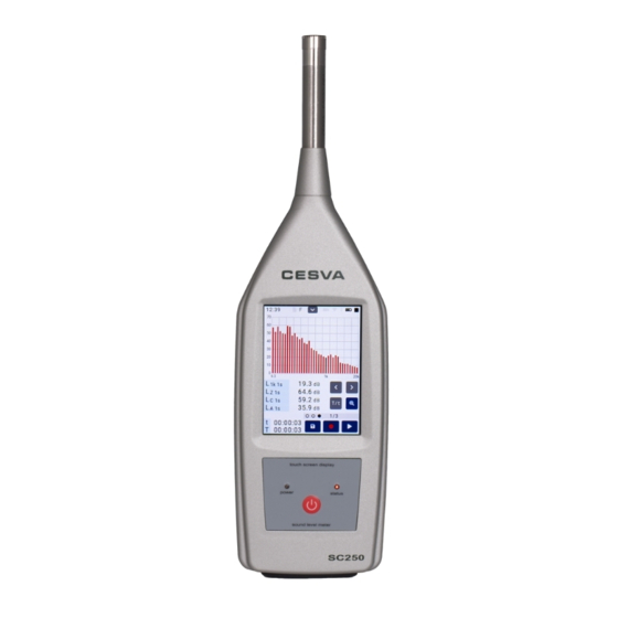
3.3 Device parts The following figure describes the most important parts of the SC250: Precision ½'' condenser microphone· The SC250 works with the C140 microphone. Preamplifier · The preamplifier of the SC250 is removable. It is connected through the LEMO connector (3). - Page 13 Chapter 3 General device description...
-
Page 14: Inputs And Outputs
Inputs and outputs 4. Inputs and outputs This chapter lists the inputs and outputs of the SC250. It indicates how to identify them and how to extract data from them. The inputs and outputs of the SC250 are on the bottom of the device, protected by a removable protective cover. -
Page 15: Keypad
Keypad 5. Keypad This chapter describes the elements that comprise the keypad. The SC250 has a touchscreen, so that the keypad area contains only one key and two LEDs. FUNCTION Key to turn the SC250 on and off. And the screen. - Page 16 STATUS OFF: The measurement is stopped ( ) STATUS ON: The measurement is paused ( ) INTERMITTENT STATUS: The device is measuring ( ) or recording ( ). In summary: SC250 Screen Measurement POWER STATUS STOP PAUSE PLAY / REC...
-
Page 17: Screen
This chapter defines the characteristics of the screen and details the information it displays. The SC250 has a 3.5” backlit colour touchscreen that allows immediate access to any type of screen or menu on the device. The data are presented both numerically and graphically. - Page 18 TIME: Shows the current time of the SC250 (hh:mm:ss). FILE: INDICATION SITUATION The final results are saved (see 16.1) A recording is made (see 16.2) A measurement that is stored in memory is displayed (see 16.4) There is no measurement on the screen A measurement is made (see 11.2)
-
Page 19: Work Area
(see 13). 6.1.3 Screen area The SC250 has different screens for displaying the data (see 13). This area indicates which screen is being displayed (SLM, 1/1 or 1/3). To change the screen that is displayed (see 13.1). -
Page 20: Available Actions Area
LED will turn on in power ON mode (see 5). NOTE If the SC250 is to be left to measure for a long period of time, a image persistence effect may occur, to avoid this possible consequence it is recommended to turn off the screen. -
Page 21: Power
Power 7. Power The first operation to be performed, before switching on the SC250, is to power it. This chapter explains the different ways to do this, as well as the configuration options that affect power. 7.1 Types of power The SC250 can be powered by batteries or via a USB connection. -
Page 22: Power By Usb
When using external power (USB), it is recommended that you insert new batteries (see 7.1.1). If you do not expect to use the SC250 for an extended period, remove the batteries from the SC250 to avoid potential damage caused by the batteries leaking. -
Page 23: Assembling And Dismantling The Device
Assembling and dismantling the device 8. Assembling and dismantling the device This chapter shows how to attach the microphone and preamplifier to the SC250, as well as all the accessories that can be installed around the microphone: windscreen, extension cable and outdoor kit. -
Page 24: Extension Cable
The SC250's microphone and preamplifier are removable. This allows the microphone to be separated from the sound level meter and the operator. By doing so, the SC250 can be operated at a distance from the measurement point, avoiding potential interference. To perform this operation,... -
Page 25: Connecting The Extension Cable
8.2.2 Connecting the extension cable First, remove the preamplifier from the sound level meter. Pass the protective cone through the extension cable's male LEMO connector (the narrow part first). Insert the extension cable's male LEMO connector into the sound level meter's female LEMO connector until you hear them click perfectly into place. -
Page 26: Outdoor Kit
In the case of using the outdoor kit, activate the respective correction in the SC250 (see 15.1.9). The TK200 requires maintenance, see the instruction manual. NOTE: The TK200 outdoor kit is not included in the normal operating mode, but as an optional accessory. -
Page 27: Switching The Device On And Off
BY POWER To turn on the SC250, you only need to power the sound level meter through the USB port. In order for the sound level meter to be switched on by means of the power, the option must be activated (see 15.1.10). -
Page 28: Sc250 Initial Self Test
To prevent this from happening, we recommend that when the SC250 is to be turned on for a long period of time, you should turn the display off (whenever possible). This action, in addition to protecting the screen, will also save batteries (when running on batteries). -
Page 29: Check The Firmware Version Of The Sc250
To check the firmware version of the SC250, access the INFORMATION option in the menu (see 15.1.13). 9.2 Turn off the device To turn off the SC250, check that there are no measurements in progress press for a couple of seconds or remove the power from the USB port (if the option is activated (see 15.1.10)). -
Page 30: Check The Device
CB006 or CB011 class 1, and follow the steps below: Place the SC250 in the calibrator, inserting the part of the microphone in the calibrator cavity. Make sure it has gone all the way into the cavity. There may be a certain amount of resistance, since the calibrator fits onto the sound level meter tightly. - Page 31 C140 microphone correction is -0.1 dB; i.e. the SC250 must be checked at 93.9 dB. Set the SC250 on a numerical sound level meter screen (see 13). As function to be displayed, select the sound pressure level with fast time averaging (FAST) L .
-
Page 32: Measuring And Recording
However, with the recording, as they are measured, they are also saved in the memory of the SC250. So if the device is turned off, the data are preserved. At the end of a RECORDING, the time history of the measured functions and the final results will be saved in a register. -
Page 33: Prior Steps
11.1 Prior steps Once the SC250 is turned on, and the device verification has been carried out (see 10.1), verify that there is no measurement in progress . Then make the prior adjustments (see 15). 11.2 Measuring With the sound level meter on, press to start a measurement. -
Page 34: Make A Recording
) the type of display screen can be changed. 11.4 Overload indicator The SC250 has an overload indicator for each function. If an overload occurs during the measurement, the indication will be added in front of the value of the function that has been affected by it. -
Page 35: Under Range" Indicator
11.5 "Under range" indicator The SC250 has an under-range indicator for each function. If the value displayed on the screen is lower than the lower limit of the linearity range, the indication will appear in front of the value of the function that meets this condition. This indication will only appear while this condition exists. -
Page 36: Menu
Menu 12. Menu With the SC250 menu it possible to: Manage memory and the saved registers. View the registers. Configure the settings of the SC250. Consult the device's own information. 12.1 Access the menu Once the SC250 is on, click on . -
Page 37: Areas Of The Menu
12.2 Areas of the menu The SC250 menu screen has the following areas: DATE/TIME AREA: Shows the current time and date of the SC250. It also shows to exit the menu (see 12.1). OPTIONS AREA: Shows the options available from the SC250 menu (see 15.1). -
Page 38: Screens
Screens 13. Screens The SC250 measures all functions simultaneously (these are detailed in Chapter 23). These functions are grouped into different screens for easy viewing. This chapter explains all the information about these screens. 13.1 Change screen When you turn on the sound level meter, the numeric sound level meter screen is displayed. -
Page 39: Actions In The Display
On the Sound Level Meter Screens the global levels of sound pressure are measured, both instantaneous and averaged values based on integration (equivalent level). The SC250 shows the functions with all the frequency weighting (A, C and Z) and the statistical data as maximum and minimum values and percentiles. - Page 40 The parameters that can be displayed are: TIME BASE FUNCTIONS 1maxt 1mint maxt 2mint AF5t ATmaxt ATmint, 1maxt 1mint 2maxt 2mint, CTmaxt CTmint ZTmaxt ZTmint Measurement time AFmaxt AFmint ASmaxt ASmint AImaxt AImint CFmaxt CFmint...
- Page 41 The SC250 allows you to modify the function to be displayed regardless of the status ( , , / or ). SOUND LEVEL METER GRAPHIC SCREEN: It shows the time history and the value of the functions F1, F2 and F3. It graphically represents the last 60 measured values.
- Page 42 Below the graph, the F1 value and the configured threshold level are shown numerically. The 1/1 Analyser Screens show in real time the equivalent continuous sound pressure level in octave bands centred on frequencies 8, 16, 31.5, 63, 125, 250, 500, 1000, 2000, 4000, 8000 and 16000 Hz (without frequency weighting).
- Page 43 1/1 GRAPHIC ANALYSER SCREEN: It shows in real time the spectral graph of the equivalent levels by octave bands 8 Hz - 16 kHz (without frequency weighting) for the consecutive integration time T, for the measurement time t and for the integration time of 1 second. It also shows the numerical value of the global equivalent level with the frequency weighting A, C and Z and that corresponding to the octave band selected in the graph (vertical cursor) for T, t and 1s.
- Page 44 The Analyser Screen (1/3) displays in real time, for the entire dynamic measurement range, the equivalent continuous sound pressure level in the 1/3 octave bands from 6.3 Hz to 20 kHz (without frequency weighting). Simultaneously, it shows the global equivalent level with frequency weighting A, C and Z.
-
Page 45: Supplementary Options
14.1 Zoom The graphic representation of the wide dynamic range of measurement of the SC250 does not allow the correct appreciation of highly stable sound events in the time history and spectral content in graphic screens. A sound event with temporal variations of a few decibels will be represented as a practically constant event. -
Page 46: Backerase
14.2 Backerase During the measurement of a sound event, especially during background noise measurements, unexpected sounds may appear that do not correspond to the sound event to be evaluated and which the sound level meter can measure. In these situations, it may be interesting to use the BACKERASE option. This option, while the measurement is temporarily stopped , allows the deletion of the last 10 seconds of the measurement or recording. -
Page 47: Settings And Adjustments
Settings and adjustments 15. Settings and adjustments From the menu, all the features of the SC250 can be configured: date and time, ® sensitivity, Bluetooth communication, WIFI network, etc. To access the menu and move through it, see 12. 15.1 Menu options... -
Page 48: Registers Option
CLOUD Check the connection of the SC250 with the server (CESVACloud) and carry out updates and extensions. INFORMATION Show information corresponding to the SC250. Once in the selected option, you can make the changes you want. ACTIVATE/DEACTIVATE AN OPTION ... -
Page 49: Memory Option
15.1.2 MEMORY option This option displays the information about the memory of the device. Also, allows you to delete all the registers in the memory of the SC250. Chapter 15 Settings and adjustments... -
Page 50: Usb Option
This option allows you to configure the SC250 as a mass storage device. After selecting the USB option, the following screen will be displayed: In order for the SC250 to behave as a mass storage device when connected to the PC, the option must be enabled. -
Page 51: Bluetooth
NOTE: To save battery, disable Bluetooth communication when it is not needed. 15.1.5 WIFI option This option allows WIFI wireless communication to be enabled and disabled. And enter the WIFI network to which the SC250 will connect to. Chapter 15 Settings and adjustments... -
Page 52: Times Option
Once the WIFI option is selected, the screen is displayed: Write the WIFI network in the SSID text box and the password in the Password text box. In order for the sound level meter to connect to the entered WIFI network, the selector must be enabled. -
Page 53: Csv Option
15.1.8 DATE AND TIME option This option allows you to set the date and time (and the time offset) of the SC250, with which the SC250 references the measurements and recordings. After selecting the DATE AND TIME option, the following screen is automatically... - Page 54 The SC250 allows the date and time to be set manually or automatically. MANUALLY Write the date and time in the corresponding text box. YYYY - MM - DD (year - month - day) HH - MM - SS (hour - minutes - seconds) To modify the time offset, press as required.
-
Page 55: Microphone Settings Option
15.1.9 MICROPHONE SETTINGS option This option allows you to select the microphone model, the sound field correction or the TK200 outdoor kit and set the sensitivity of the SC250. NOTE: The sensitivity of the sound level meter can only be adjusted by authorised and technically competent personnel. -
Page 56: Power Option
Each time a sensitivity setting is made, the sound level meter saves a log in drive B of the internal memory (see 17.2.1) IMPORTANT: The SC250 is factory set with calibrated standards according to current regulations. The sensitivity of the sound level meter can only be set by authorised, technically competent personnel. -
Page 57: Cloud Option
To set a waiting time, type the desired minutes in the text box and then enable AUTO OFF. 15.1.12 CLOUD option This option allows it to be verified that the SC250 has successfully connected with the CESVACloud server. NOTE: For the device to be able to connect to the server (CESVACloud), the WIFI option must be enabled. -
Page 58: Registers And Memory Management
The values of the measured functions can be stored in the memory of the SC250. By turning it off, saved data are not lost and can be retrieved, viewed and erased directly from the SC250 itself or copied from memory to a computer. -
Page 59: Make A Recording
The saved functions are detailed below: TIME BASE FUNCTIONS FINAL RESULT 1maxt 1mint 2maxt 2mint AF5t ATmaxt ATmint, 1maxt 1mint 2maxt 2mint, CTmaxt CTmint ZTmaxt ZTmint Measurement time AFmaxt AFmint ASmaxt ASmint AImaxt AImint CFmaxt... - Page 60 Evaluation of the NC (8 Hz – 16 kHz) and NR (8 Hz – 16 kHz) curves f: 8, 16, 31.5, 63, 125, 250, 500, 1000 (1k), 2000 (2k), 4000 (4k), 8000 (8k) and 16000 (16k) Hz. f: 6.3, 8.10, 12.5, 16, 20, 25, 31.5, 40, 50, 63, 80, 100, 125, 160, 200, 250, 315, 400, 500, 630, 800, 1000 (1k), 1250 (1.25k), 1600 (1.6k), 2000 (2k), 2500 (2.5k), 3150 (3.15k), 4000 (4k), 5000 (5k), 6300 (6.3k), 8000 (8k), 10000 (10k), 12500 (12.5k), 16000 (16k) and 20000 (20k) Hz.
-
Page 61: Structure Of A Register
16.3 Structure of a register Each time a final result is saved or a recording is made, the SC250 stores a register in memory. For each register, a name is shown, which consists of: DATE and TIME LABEL_ REGISTER No. -
Page 62: Use Of The Inputs And Outputs
Use of the inputs and outputs 17. Use of the inputs and outputs The digital inputs and outputs and the AC output of the SC250 are detailed below. AC output: Analogue output Communication inputs/outputs: USB: Digital communication. Compliant with USB 2.0 Type C full-speed ... -
Page 63: Digital Inputs And Outputs
The USB connector [16] is of the USB type C. To connect with a computer, use the CN500 cable. With this input/output it is possible to: Power the SC250 by connecting it to a PC, a power bank or a power supply. Access data stored in memory. - Page 64 csv file for every 24 hours of recording for each time base (T, t, 1s, 20ms*). * To save the data with the 20ms time base see 15.1.7. Drive B* includes csv files that list the settings made (Clock, Firmware and Settings). * To view drive B, use a PC with Microsoft Windows (Windows10), Mac OS X, or Linux operating system.
-
Page 65: Bluetooth Communication
To connect the SC250 sound level meter to the SC250 Link To communicate the SC250 with a device (PC, Tablet, mobile, etc.) via a protocol. To obtain the protocol, contact your official retailer. ® NOTE: To save battery, disable Bluetooth communication when this communication is not needed. -
Page 66: Accessories
Accessories 18. Accessories The accessories supplied with the SC250 and the optional accessories that can be purchased additionally are listed below. 18.1 Accessories supplied The following accessories are supplied with the SC250: MODEL DESCRIPTION CN500 PC connection cable (USB type C - USB) - Page 67 CN030 Microphone extension cable 30 m TR001 Tripod adaptor PR003 Extendable pole of 3 m NOTE: only guarantees that the device will work properly when original accessories are used. Any damage caused to the device due to the use of non-original accessories is excluded from the guarantee. Chapter 18 Accessories...
-
Page 68: Technical Specifications
IEC 61672-1:2013, Class 1, Group X and Z IEC 61260-1:2014, Class 1 The class of the SC250 according to the IEC 61672-1 standard for the response to sound waves incident on the microphone in the reference direction in a free field depends on the microphone incorporated. -
Page 69: Microphones And Preamplifiers
The table below shows the technical features of the microphones and the accessories that attach to them. 19.2.1 Microphone models and their main features The SC250 as class 1 can incorporate the following microphone models of the brand: C140. MICROPHONE... -
Page 70: Frequency Response
0.00 0.13 0.10 0.14 1000 0.10 0.14 2000 0.30 0.16 4000 1.10 0.21 8000 3.10 0.28 12500 6,30 0.35 16000 7.90 0.43 CORRECTION OF THE RESPONSE OBTAINED WITH THE ELECTROSTATIC ACTUATOR BRAND B&K MODEL UA035 TO FREE-FIELD: C140 FREQUENCY [Hz] Correction [dB] Uncertainty [dB] 31.5... - Page 71 -0.01 0.01 125,893 -0.01 0.00 158,489 -0.02 0.00 199,526 0.02 0.00 251,189 0.00 0.00 316,228 -0.04 0.00 398,107 -0.07 0.00 501,187 -0.01 0.00 630,957 -0.03 0.00 794,328 -0.03 0.00 1000 1000 -0.04 0.00 1059,25 -0.03 0.00 1122,02 -0.04 0.00 1188,50 -0.04 0.00 1250...
- Page 72 5000 5011.87 -0.09 0.00 5308.84 -0.12 0.02 5623.41 -0.13 0.02 5956.62 -0.10 0.02 6300 6309.57 -0.12 0.02 6683.44 -0.24 0.02 -0.31 7079.46 0.02 7498.94 -0.33 0.02 -0.44 8000 7943.28 0.02 8413.95 -0.55 0.02 -0.67 8912.51 0.02 9440.61 -0.81 0.02 10000 10000 -0.87 0.02...
- Page 73 316,228 -0.02 0.03 398,107 -0.01 0.03 501,187 -0.02 0.03 630,957 -0.03 0.03 794,328 -0.02 0.03 1000 1000 0.02 0.06 1059,25 0.04 0.06 1122,02 0.04 0.06 1188,50 0.05 0.06 1250 1258,93 0.07 0.06 1333,52 0.10 0.06 1412,54 0.10 0.06 1496,24 0.11 0.06 1600 1584.89...
- Page 74 7.45 0.11 14962.4 7.60 0.11 16000 15848,9 8.10 0.22 Free-field response of the SC250 to sinusoidal plane waves relative to the corresponding free-field response in the reference direction SC250 FREQUENCY [Hz] Correction Uncertainty Exact in base 10 [dB] [dB] 251,189 0.00...
- Page 75 1496,24 -0.08 0.00 1600 1584.89 -0.03 0.00 1678. 80 -0.03 0.00 1778.28 -0.09 0.00 -0.07 0.00 1883.65 2000 1995.26 -0.03 0.00 2113.49 0.00 0.00 2238.72 -0.10 0.00 2371.37 -0.15 0.00 -0.11 0.00 2500 2511.89 2660.73 -0.02 0.00 -0.12 0.00 2818.38 2985.38 -0.16 0.00...
- Page 76 16000 15848,9 Correction for the average effects of the reflections of the sound level meter case and the diffraction around the microphone for plane progressive sound waves incident in the reference direction: SC250 FREQUENCY [Hz] Correction Uncertainty Exact in base 10...
- Page 77 2238.72 -0.07 0.00 2371.37 -0.15 0.00 2500 2511.89 -0.10 0.00 2660.73 0.04 0.00 2818.38 -0.08 0.00 2985.38 -0.11 0.00 3150 3162.28 0.00 0.00 3349.65 -0.01 0.00 3548.13 -0.13 0.00 3758.37 -0.06 0.00 4000 3981.07 -0.09 0.00 4216.97 -0.15 0.00 4466.84 -0.14 0.00 -0.19...
- Page 78 Correction for the average effects of the PV009 windscreen on the frequency response of the sound level meter in the absence of wind: PV009 FREQUENCY [Hz] Correction Uncertainty Exact in base 10 [dB] [dB] 1000 1000 0.35 0.00 1250 1258,93 0.50 0.00 1600...
- Page 79 RESPONSE WITH RANDOM INCIDENCE IN A DIFFUSE FIELD: Correction for the average frequency response of the SC250 sound level meter, with the sound field correction set for diffuse field, for the response with random incidence in a diffuse field: SC250...
- Page 80 398,107 0.14 501,187 0.09 630,957 0.19 794,328 0.19 1000 1000 0.27 1250 1258,93 0.33 1600 1584.89 0.47 2000 1995.26 0.57 2500 2511.89 0.80 3150 3162.28 0.71 4000 3981.07 -0.02 5000 5011.87 -0.52 6300 6309.57 -0.40 8000 7943.28 -0.62 10000 10000 -1.63 12500 12589.3...
-
Page 81: Effect Of The Optional Accessories On The Microphone
-3.17 0.21 The SC250 with the protective connector cover and the TK200 outdoor kit has an IP65 degree of protection. CABLES The cables do not have any effect inside the measuring frequency band. A recalibration is not necessary when using the extension cables. -
Page 82: Directional Response
Sound level meter directional response to plane progressive waves with 30°, 90° and 150º angles of incidence, including the reference direction. Maximum variation of sensitivity at 30°, 90° and 150° with respect to the reference direction extended with the expanded measurement uncertainty SC250 Vertical and Horizontal Plane FREQUENCY Variation at 30º [dB] Variation at 90º [dB] Variation at 150º... - Page 83 SOUND LEVEL METER: HORIZONTAL PLANE DIRECTIVITY DIAGRAMS: SOUND LEVEL METER: VERTICAL PLANE DIRECTIVITY DIAGRAMS: Chapter 19 Technical specifications...
- Page 84 150° angle of incidence including the reference direction: Maximum variation of sensitivity at 30°, 90° and 150° with respect to the reference direction extended with the expanded measurement uncertainty SC250 + PV009 Vertical and Horizontal Plane FREQUENCY Variation at 30º [dB] Variation at 90º...
- Page 85 SOUND LEVEL METER + WINDSCREEN: HORIZONTAL PLANE DIRECTIVITY DIAGRAMS: SOUND LEVEL METER + WINDSCREEN: VERTICAL PLANE DIRECTIVITY DIAGRAMS: Chapter 19 Technical specifications...
- Page 86 Directional response of the microphone with TK200 outdoor kit to progressive plane waves with 30°, 90° and 150° angle of incidence including the reference direction: Maximum variation of sensitivity at 30°, 90° and 150° with respect to the reference direction extended with the expanded measurement uncertainty Vertical and Horizontal Plane C140 + TK200 FREQUENCY...
- Page 87 MICROPHONE AND OUTDOOR KIT: HORIZONTAL PLANE DIRECTIVITY DIAGRAMS: MICROPHONE AND OUTDOOR KIT: VERTICAL PLANE DIRECTIVITY DIAGRAMS: Chapter 19 Technical specifications...
-
Page 88: Directivity Indexes
19.2.6 Directivity indexes The directivity indexes to determine the relative frequency weighted response for random incidence of the SC250 sound level meter are shown below. FREQUENCY [Hz] SC250 Exact in base 10 Correction [dB] 251.19 0.11 316,23 0.06 398.11 0.02 501.19... - Page 89 -6.50 20000 19,952.60 -6.85 The directivity indexes to determine the relative frequency weighted response for random incidence of the SC250 sound level meter and PV009 windscreen are shown below. FREQUENCY [Hz] SC250 + PV009 Exact in base 10 Correction [dB] 251.19...
- Page 90 2371.37 -0.51 2500 2511.89 -0.53 2660.73 -0.56 2818.38 -0.58 2985.38 -0.59 3150 3162.28 -0.59 3349.65 -0.62 3548.13 -0.70 3758.37 -0.81 4000 3981.07 -0.93 4216.97 -1.04 4466.84 -1.20 4731.51 -1.43 5000 5011.87 -1.72 5308.84 -1.97 5623.41 -2.07 5956.62 -2.08 6300 6309.57 -2.13 6683.44 -2.20...
-
Page 91: Preamplifier Connector
19.2.7 Preamplifier connector The connection of the PA020 preamplifier to the SC250 is made through LEMO-type connectors. The sound level meter has a female LEMO connector and the preamplifier has a male LEMO connector. The pins of this connector are as follows (external view of the connectors):... -
Page 92: Linearity Range
Tables of nominal A-weighted sound levels at the upper and lower limits of the linear operating ranges in each level range (f). Typical linearity range for SC250 sound level meter with C140 microphone and PA020 preamplifier: Frequency [Hz] Weighting A [dB]... -
Page 93: Noise
(i): Self-generated noise of the SC250 sound level meter with C140 microphone and PA020 preamplifier: A Weighting [dB] C Weighting [dB]... -
Page 94: Frequency Weighting
19.3.6 Frequency weighting The following table lists the frequency weightings available for each function FUNCTION WEIGHTING peak A or C A, C or Z A, C or Z A or C The following table shows the A, C and Z frequency weightings and tolerance for class 1. FREQUENCY A WEIGHTING C WEIGHTING... -
Page 95: Calibration
CB006 or CB011 acoustic calibrator and consult section 10.1. 19.5 OCTAVE AND THIRD OCTAVE BAND FILTERS The SC250 has class 1 octave band and third octave band filters according to the IEC 61260-1:2014 standard. 19.5.1 Octave and third octave band filters... - Page 96 OCTAVE BAND FILTERS THIRD OCTAVE BAND FILTERS NOMINAL CENTRAL EXACT BASE 10 NOMINAL CENTRAL EXACT BASE 10 FREQUENCY FREQUENCY FREQUENCY FREQUENCY [Hz] [Hz] [Hz] [Hz] 6.310 7.943 7.943 10,000 12.5 12,589 15,849 15,849 19.953 25,119 31.5 31.623 31.5 31.623 39,811 50,119 63.096 63.096...
-
Page 97: Measurement Range (Octave Band Spectrum Analyser)95
19.5.2 Measurement range (octave band spectrum analyser) Measurement range (with linearity error lower than 0.4 dB): MICROPHONE C140 FREQUENCY [Hz] Range [dB] from 20.7 to 137 from 17.0 to 137 31.5 from 13.9 to 137 from 11.6 to 137 from 10.0 to 137 from 9.8 to 137 from 11.1 to 137 1000... -
Page 98: Environmental, Electrostatic And Radio Frequency Criteria
from 7.0 to 137 from 7.0 to 137 from 7.0 to 137 from 7.0 to 137 from 7.0 to 137 from 7.0 to 137 from 7.6 to 137 1000 from 8.4 to 137 1250 from 9.2 to 137 1600 from 10.0 to 137 2000 from 10.9 to 137 2500... -
Page 99: Electrostatic Criteria
Configuration with CN010 extension cable of microphone and SC250 sound level meter with function L REFERENCE ORIENTATION: SC250 in vertical position, with the principal axis of the SC250 (preamplifier) perpendicular to the direction of propagation of the field in horizontal polarisation. With all the cables connected and... - Page 100 (*) Sound level meter with L function. SC250 in vertical OPERATING MODE AND POSITION THAT position, with the principal axis of the SC250 perpendicular to the PRODUCES THE MAXIMUM EMISSION OF direction of propagation of the field with horizontal polarisation.
-
Page 101: Inputs And Outputs
19.7 INPUTS AND OUTPUTS 19.7.1 AC output TYPE OF OUTPUT: analogical output directly proportional to the preamplifier output FREQUENCY WEIGHTING: Without weighting TYPICAL VOLTAGE AT 94 dB and 1 kHz: 46 mVrms MAXIMUM VOLTAGE: 24 Vpp (usual) OUTPUT IMPEDANCE: 100 RECOMMENDED RANGE OF OUTPUT RL ... -
Page 102: Screen
0.1 dB 19.9 POWER 19.9.1 Batteries The SC250 can be powered by three types of batteries, so the type of battery to be used must be indicated (see 15.1.10). TYPES OF BATTERIES: 3 x 1.5 V alkaline batteries, AA (LR6) size 3 x 1.5 V lithium batteries, AA (LR6) size... -
Page 103: External Power
5 V DC 5% MINIMUM CURRENT: To power the SC250 from a mains supply, the use of the AM300 mains transformer and the CN500 cable is recommended. declines all responsibility for the use of power supplies other than those recommended. -
Page 104: Certificates
19.11.2 Certificates Type approval Certificate for Spain 19.11.3 Notes If your SC250 stops complying with any of these specifications, contact your nearest official dealer for inspection, adjustments or repair. Chapter 19 Technical specifications... -
Page 105: Maintenance And Precautions
Only attach or detach the microphone using your hands, never use tools. Never do this when the SC250 is operating. If a 200 V polarised microphone is used, and the sound level meter is switched on, there will be 200 volts at the central preamplifier contact. - Page 106 Use the SC250 only for the purpose for which it was designed. If the user works with the device for other purposes, the device could be damaged. ...
-
Page 107: Tips For Taking Measurements
Any impact on the SC250 will be picked up by the microphone and may affect the measurement value and permanently damage it. ... -
Page 108: Firmware Update And Module Activation
Without the need to send the device to the technical service. This saves a great deal of time and money. Optional modules can be purchased at the time of purchase of the SC250 or at a later date. To incorporate them, simply contact your official... -
Page 109: Activation Of An Optional Module Of The Sc250
At this moment, the sound level meter can be turned on. 22.2 Activation of an optional module of the SC250 Optional modules can be purchased at the time of purchase of the SC250 or at a later date. To incorporate them, simply contact your official... -
Page 110: Activating An Optional Sc250 Link Module
22.3 Activating an optional SC250 Link module To incorporate an optional module to the SC250 Link application, simply contact your official retailer and provide them with the serial number of your sound level meter and manage the module acquisition procedures. -
Page 111: Functions
Functions 23. Functions 23.1 Nomenclature of functions The functions that the SC250 measures, their nomenclature and a brief definition of these are specified below. 23.1.1 Sound level meter parameters FUNCTION DESCRIPTION Sound pressure level with A frequency weighting and fast time weighting (Fast) - Page 112 Peak sound pressure level of T and t time with C frequency weighting Cpeak Peak sound pressure level of 1 s with C frequency weighting Cpeak1s Total percentiles Partial percentiles of T integration time n: 1%, 5%, 10%, 50%, 90%, 95%, 99%. The percentiles are calculated from a sampling time of 20 ms and with classes of 0.1 dB Equivalent continuous sound pressure level with t integration time with X frequency weighting...
-
Page 113: 1/1 Octave Band Parameters
: These functions are measured by the SC250 but are not displayed on the screen. The way to obtain the results of these functions is by making a recording and later viewing the csv file from the PC (see 17.2.1). -
Page 114: 1/3 Third Octave Band Parameters
23.1.3 1/3 third octave band parameters FUNCTION DESCRIPTION Equivalent continuous sound pressure level with t integration time of the third octave band centred on frequency f Equivalent continuous sound pressure level with T integration time of the third octave band centred on the frequency f Equivalent continuous sound pressure level with 1 second integration time of the third octave band centred on the frequency f f: 6.3, 10, 12.5, 16, 20, 25, 31.5, 40, 50, 63, 80, 100, 125, 160, 200, 250, 315, 400, 500,... -
Page 115: Description Of Functions
23.2 Description of functions This section briefly describes the functions that the SC250 measures for the various measurement modes. 23.2.1 Sound pressure level with Fast and Slow time weighting (Fast) RMS value with 125 ms fast exponential averaging, in decibels. -
Page 116: Sound Pressure Level With Impulse Time Weighting
23.2.2 Sound pressure level with Impulse time weighting (Impulse) Maximum short-term RMS value with exponential averaging of 35 ms, in decibels. EXPONENTIAL PEAK p(t) AVERAGING DETECTOR ... = 35 ms = 1.5 s = 20Pa p(t): instantaneous sound pressure The Impulse feature is designed to detect impulse noise, like shots or blows. -
Page 117: Taktmaximal-Mittelungspegel
T integration time (a programmable parameter). Every time T interval is presented. That is, every T interval, the SC250 shows the equivalent level of the last T interval. The equivalent level L is the equivalent level corresponding to the sliding integration time each second. -
Page 118: Percentiles
23.2.6 Percentiles and L These are the levels that have been exceeded for 99%, 95%, 90%, 50%, 10%, 5% and 1% of the measurement time, in decibels. On the sound level meter screen, they are calculated with 0.1 dB classes from a sampling time of 20 ms. -
Page 119: Reference To Standards
Description of the frequency weightings 19.3.6 Frequency weighting provided 5.1.12 Description of the level range with the nominal 19.3.2 Measurement range value A-weighted at 1 kHz The SC250 has one unique range Recommendation for selecting the optimal range Chapter 24 Reference to standards... - Page 120 19.2.1 Microphone models and their main features microphone and input peak-to-peak voltage value 5.1.18 Description of each independent input channel The SC250 has only one input channel 5.1.19 Initial time interval after power on 19.3.1 Warm-up time Adjustments to the calibration check frequency 5.2.1...
- Page 121 Operation and interpretation of “under range” The “under range” indication is not necessary as the indications. SC250 has only one range, the lower limit of which is determined by the inherent noise of the microphone and electronic components within the sound level meter.
- Page 122 5.15.6 Alternative results presentation devices The SC250 does not have any alternative results presentation devices. 5.19 Analogue or digital output 5.19.1 Features of the analogue or digital outputs 4 Inputs and outputs 17 Use of the inputs and outputs 19.7 INPUTS AND OUTPUTS 5.20...
- Page 123 Electrostatic discharges 6.5.2 Degradation due to exposure to electrostatic 19.6.3 Electrostatic criteria discharge. Fields at the frequency of the alternating power network and radio frequency 6.6.1 Configuration that produces the maximum 19.6.4 Criteria of the fields at the frequency of the susceptibility (minimum immunity) to the fields mains supply and radio frequency fields.
- Page 124 The SC250 has only one range. weighted sound levels at 1kHz. 19.3.2 Measurement range 9.2.2 f) Operation of the level range controls There is no level range control. The SC250 has only one range. 9.2.2 g) A description of the results presentation devices 6 Screen and the frequencies for updating the results.
- Page 125 9.2.2 k) Information on the target design characteristics All additional functions to those specified in this and the limits of acceptance that should be standard meet the characteristics specified in the maintained for the quantities that the sound standard that is contained in its definition. level meter is capable of indicating but for which 23 Functions performance specifications are not provided in...
- Page 126 11.5 "Under range" indicator them. 9.2.6 k) Operation of any user-selectable threshold for The SC250 does not provide thresholds measurements of time-averaged sound levels or sound exposure levels. 9.2.6 l) The method of downloading digital data to a PC 17 Use of the inputs and outputs 9.2.6 m)
- Page 127 9.2.8 c) Declaration of conformity with the specifications 19.6.4 Criteria of the fields at the frequency of the of immunity to fields at the frequency of the mains supply and radio frequency fields. alternating power network or radio frequency. Possibility of indicating a sound level lower than 74 dB for which the sound level meter meets the specifications for the exposure of radio frequency fields.
-
Page 128: Standard Une-En 61260-1:2014
24.2 Standard UNE-EN 61260-1:2014 PARAGRAP DESCRIPTION SECTION Manual SC250 H IEC 61260 PERFORMANCE REQUIREMENTS 5.1.4 The configuration of the filter for one of the 13 Screen normal modes of operation, including required accessories. Reference attenuation 5.9.1 Reference attenuation 19.5.1 Octave and third octave band filters 5.9.2... - Page 129 FILTERS performance requirements of this standard 7.1 b) For each analysis channel, a list of nominal The SC250 has only one channel mid-band frequencies for all filters for all filters of each available filter bandwidth 7.1 c) Reference attenuation 19.5.1 Octave and third octave band filters...
- Page 130 7.2 h) The recommended means to check that the 7 Power electrical power supplied is sufficient to operate the instrument 7.2 i) The identification of the specific instrument 3.3 Device parts 7.2 k) The maximum time needed after switching on 19.6.1 Stabilisation time the instrument before the instrument may be used to measure filtered output signal levels...
- Page 132 Maracaibo, 6 08030 Barcelona (Spain) Tel. (+34) 934 335 240 www.cesva.com info@cesva.com...
Need help?
Do you have a question about the SC250 and is the answer not in the manual?
Questions and answers