Table of Contents
Advertisement
Quick Links
Advertisement
Table of Contents

Related Manuals for CESVA SC-30


Summary of Contents for CESVA SC-30
- Page 1 SC-30 Sound Level Meter Spectrum Analyser User’s Manual M_SC30_v2007_20101228_ENG...
- Page 2 NOTE: This version of the manual is valid for instruments with serial number from T223527...
-
Page 3: Table Of Contents
2.4.3 Functions display ....................22 2.4.4 Stopping and pausing the measurement ...............24 2.4.5 Consulting the measured data................24 2.5 Overload and over range indicator ................24 2.6 The SC-30 menu: Register management and configuration ........25 2.6.1 Accessing the menu....................25 2.6.2 The SC-30 menu....................25... - Page 4 2.6.3 Register management...................26 2.6.4 Printing........................26 2.6.5 Settings.........................26 2.7 Turning the SC-30 off ....................27 2.8 Precautions .........................28 3. DATA REGISTRATION ....................30 3.1 Saving results......................30 3.2 Making a recording......................31 3.3 Kinds of recording .......................31 3.3.1 Recording in sound level meter mode ..............31 3.3.2 Recording in spectrum analyser mode ..............32...
- Page 5 7.3.4 Beginning a measurement ..................53 7.3.5 Stopping the measurement ...................55 7.3.6 Overload and Over range indicator ...............55 7.3.7 Indicator (---) ......................56 7.3.8 Turning the SC-30 off....................56 7.3.9 Menu of SC-30......................56 7.4 Data register........................56 7.4.1 Saving results .......................56 7.4.2 View register ......................57 7.5 Technical Specifications....................57...
- Page 6 8. APPENDIX C: Dosimeter Module for the assessment of noise at workplace.....60 8.1 Dosimeter module activation ..................60 8.2 Using the keyboard for the dosimeter mode ..............61 8.3 Using the SC-30......................61 8.3.1 Switch on the SC-30 .....................61 8.3.2 Accessing to the Dosimeter mode.................61 8.3.3 Turn off the SC-30....................62 8.3.4 SC-30 Menu......................62 8.4 Measuring in dosimeter mode ..................62...
-
Page 7: General Features
60651:01 and IEC 60804:00 international regulations and their EU counterparts EN 60651:94/A1:94/A2:01 and EN 60804:00. The SC-30 is also a spectrum analyser measuring in real time and in octave bands. It covers a frequency range from 22 Hz and 22,5 kHz with type-1 octave filters, which comply with IEC 61260:1995/A1:01. -
Page 8: Main Features Of The Sc-30
The most important features of the SC-30 are the following: • The SC-30 has a single user range; there is therefore no need to adjust the scale prior to beginning a measurement, whatever the sound event to be measured. •... -
Page 9: Description Of The Sc-30
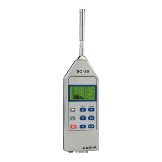
SC-30 User’s Manual 1.3 Description of the SC-30 The main components of the SC-30 are listed below, the numbers corresponding to those in the outline drawing: 1. ½’’ condenser microphone. The SC-30 works with either with the C-130 microphone (polarised at 200 V) + PA-13 preamplifier or the C-250 pre-polarised microphone + Pa-14 preamplifier. -
Page 11: Screen
SC-30 User’s Manual 1.4 Screen The current SC-30 mode is always indicated in the top right-hand corner of the screen: • Sound Level meter mode • Octave band Spectrum Analyser While the SC-30 is measuring, the following information appears at the bottom right of the screen: •... - Page 12 Key to begin or terminate a measurement a) Key to temporarily interrupt a measurement (PAUSE) ►) (while the SC-30 is in b) To start recording data into memory (when SC-30 is stopped i.e. Key to select the frequency weighting displayed on the screen...
-
Page 13: Using The Sc-30
2.1.2 SC-30 power supply Before you turn the SC-30 on, the first thing you must do is connect it to a battery or other power supply. Note: The components referred to in the text are indicated on the outline on page 7 and listed in parenthesis, e.g. -
Page 14: Connecting And Disconnecting The Preamplifier, Using The Extension Cable And The Outdoor Kit
When an external power source is used (mains feeder or battery), it is recommended that new batteries be fitted. If you are not going to use the SC-30 for some time, remove the battery to prevent damage caused by battery leakage. - Page 15 SC-30 User’s Manual To reconnect the preamplifier to the sound level meter, introduce the preamplifier LEMO male plug ( 3) into the sound level meter LEMO socket ( 4) until they click together. The red dot on the preamplifier connector must coincide with the red dot on the sound level meter connector.
-
Page 16: Beginning A Measurement
A few seconds later, the initial screen predetermined in the menu configuration option will appear. If the SC-30 does not switch on, check that a fully charged battery is fitted or that it is connected to a suitable power supply. - Page 17 Readjustment of the sensitivity entails the loss of traceability in the calibration of the instrument. If the results of checking the SC-30 show a deviation of more than 0.3 dB, adjust the sensitivity as follows: 1) Press the key to terminate the measurement process.
-
Page 18: Measuring In Sound Level Meter Mode
4) Access the SETTINGS SENSITIVITY ADJUST option. 5) The display will show the sound pressure level measured by the SC-30 and the time and date of the last time the sensitivity was modified: 6) Use the keys to adjust the calculated value (94 dB + corrections). - Page 19 SC-30 User’s Manual When the previous screen appears, select the function you want to configure, F1, F2, F3 or T, by using the keys, then press Use the key to cancel Modify the F1, F2 and F3 functions as follows: •...
-
Page 20: Beginning A Measurement
), press to stop it. Next, switch the SC-30 to sound level meter mode and select the screen you want to see displayed (numeric, graphic or statistical sound level meter), either from the SC-30 menu or by pressing the keys:... - Page 21 SC-30 User’s Manual • The main function (large digits) • The secondary functions: except on the preferential screen, these are the maximum and minimum values of the main function (see table). Main Secondary Secondary function function 1 function 2 XFmax...
-
Page 22: Stopping And Pausing The Measurement
2.3.5 Consulting the measured data While the SC-30 is stopped ( ) you can consult all the functions measured. The way to consult them is the same as the one in section 2.3.3. for displaying data while measurement is in progress. -
Page 23: Measuring In Spectrum Analyser Mode
First, check that there is no measurement in progress ( ). If there is ( ), press to stop it. Next, switch the SC-30 to spectrum analyser mode and select the screen you want to display (numeric or graphic analyser), either through the SC-30 menu or using the keys:... -
Page 24: Functions Display
2.4.3 Functions display The SC-30 measures all the functions simultaneously. Below is described the different ways to display the acoustic functions while measurement is in progress. If you change the kind of display, the octave band or the frequency weighting, the measurement continues. While measurement is in progress, you cannot switch from the spectrum analyser mode to the sound level meter mode. - Page 25 SC-30 User’s Manual • A graph of the equivalent continuous sound pressure levels with T integration time (bars [ ]) in real time for octave bands centred on the frequencies 31.5, 63, 125, 250, 500, 1,000, 2,000, 4,000, 8,000 and 16,000 Hz (without frequency weighting).
-
Page 26: Stopping And Pausing The Measurement
When over appears in the indication of the value of a function, this means that the measured value exceeds the upper limit of the measurement range (over-range). When this happens, the maximum range of the SC-30 has been exceeded and the actual level cannot be known, thus any such measurements should be discarded. -
Page 27: The Sc-30 Menu: Register Management And Configuration
SC-30 User’s Manual 2.6 The SC-30 menu: Register management and configuration This section covers all the options accessible from the SC-30 menu, the major features of which include register management and SC-30 configuration (screens, language, date and time, etc). When supplied, the SC-30 is already programmed with an initial configuration that allows you to carry out measurements without first having to reconfigure the instrument before beginning to measure. -
Page 28: Register Management
4.3 2.6.5 Settings • SETTINGS: This option allows you to configure several features of the SC-30, such as definition of the initial screen, adjustment of the clock/calendar, of the language or of the sensitivity of the SC-30. SETTINGS... -
Page 29: Turning The Sc-30 Off
DATE AND TIME This option allows you to adjust the date and time of the SC-30 clock. 2.7 Turning the SC-30 off To turn the SC-30 off, first make sure that no measurement is in progress ( ), then press:... -
Page 30: Precautions
When attaching or detaching the microphone, use the fingers only, never use tools. And never do it when the SC-30 is functioning. Note, if a 200 volt polarised microphone is in use there will be 200 volts on the centre pin if the unit is ON. This is not dangerous, but may cause you to drop the microphone capsule. - Page 31 SC-30 User’s Manual This equipment only can work with the accessories mentioned in the accessories section. In case that using a different accessories and that this causes a failure in the equipment, would not be responsible of this failure. Then the equipment will lose its...
-
Page 32: Data Registration
Maximum peak sound pressure level of the T interval and with frequency weightings A, C and Z The integration time T. The SC-30 may store a total of 1,000 final results in both sound level meter mode and spectrum analyser mode. -
Page 33: Making A Recording
3.3.1 Recording in sound level meter mode The option SETTINGS SLM RECORDING configures the periods and the functions that SC-30 stores in the memory while recording in sound level meter mode. Four possibilities exist: • ALL each second: this saves all the functions measured in sound level meter mode (see 3.1.) second by second. -
Page 34: Recording In Spectrum Analyser Mode
NOTE: If the power supply to the sound level meter is suddenly interrupted in the middle of a recording, the recording will be incomplete and will not be displayed on screen of the SC-30. The “INCOMPLETE RECORDING” message will appear on screen when recovering. We... -
Page 35: Data Transfer
The communications software supplied with the SC-30 ( Capture Studio) allows you to carry out the following operations: • Transmission to a PC, in real time, of data measured by the SC-30. • Downloading of the registers stored by the SC-30. •... -
Page 36: The Ac Output: Recording Calibrated Measurements
The SC-30 AC output also allows you to hear which signal is being measured and to verify whether it is being influenced by noises other than those being measured. - Page 37 SC-30 User’s Manual The serial printer must have 80 columns. The format for printing is the same that it is used for the data transference in section 4.1.
-
Page 38: Technical Specifications
5. TECHNICAL SPECIFICATIONS 5.1 Measurement range and L functions Lower limit of the indicator: 0 dB Upper limit of the indicator: 137.0 dB Operating limits are modified by the sensitivity of the microphone. For C-130 + PA-13: FREQUENCY WEIGHTING Primary Range Upper limit 120.0 120.0... -
Page 39: Detector - Functions L , L And L
SC-30 User’s Manual For C-250 + PA-14: FREQUENCY WEIGHTING Primary Range Upper limit 120.0 120.0 120.0 Lower limit 50.0 50.0 50.0 Measurement Range (with nominal sensitivity of the microphone) at 1kHz: 137.0 137.0 137.0 Upper limit 130.0 130.0 130.0 Upper limit for crest factor 3: 126.0... -
Page 40: Peak Detector - L Function
Maximum overshot: 1.1 dB 1.6 dB Maximum error of level linearity (31.5 to 12500 Hz): ± 0.7 dB Maximum error of differential level linearity( 31.5 to 12500 ± 0.2 dB Hz): Peak detector - L function 2.9 dB/s ± 0.5 dB/s Decay rate: Onset time constant: <... -
Page 41: Ac Output
SC-30 User’s Manual Frequency Weighting A Weighting C Tolerance for type 1 (dB) (Hz) (dB) (dB) - 56.7 - 8.5 + 3; -∞ ± 1.5 31.5 - 39.4 - 3.0 ± 1.5 - 26.2 - 0.8 ± 1 - 16.1 - 0.2... -
Page 42: Measurement Range (Octave Band Spectrum Analyser)
Octave band nominal central frequencies Nominal central frequency Exact base 10 frequency 31.5 Hz 31.623 63 Hz 63.096 125 Hz 125.89 250 Hz 251.19 500 Hz 501.19 1 kHz 1,000 2 kHz 1,995.3 4 kHz 2,511.9 8 kHz 7,943.3 16 kHz 15,849 5.8 Measurement range (octave band spectrum analyser) Function... -
Page 43: Microphone
SC-30 User’s Manual 5.9 Microphone C-130 ½ ″ condenser microphone Polarisation 200 V Nominal capacitance 22.5 pF Nominal sensitivity: 17.5 mV/Pa ± 0.5dB in reference conditions Effect of the windscreen < 1 dB for frequencies < 10 kHz < 3 dB for frequencies < 12.5 kHz... -
Page 44: Diffuse Field Sensitivity (S)
5.10 Diffuse field sensitivity (S) C130 microphone Frequency (Hz) S (mV/Pa) 2,000 26.44 3,000 17.35 4,000 20.61 12,500 12.05 5.11 Directivity Sensitivity variation at 30° and 90° Frequency (Hz) 30° (dB) 90° (dB) 40 – 1,000 1,000 – 2,000 2,000 – 4,000 4,000 –... -
Page 45: Reference Conditions
SC-30 User’s Manual 5.12 Reference conditions Type of sound field: Free Reference direction Perpendicular to the microphone diaphragm 94 dB (referred to 20 µPa) Reference sound pressure level: Reference frequency: 1 kHz Reference temperature: 20 ° C Reference relative humidity:... -
Page 46: Warm-Up Time
5.16 Magnetic field influence Influence of the Magnetic Fields In a magnetic field of 80 A/m (1 oersted) at 50 Hz, the reading will be under 25 dB(A) Sound pressure level at which the SC-30 74 dBA meets requirements radiated electromagnetic field. -
Page 47: Battery & External Supply
573 g 5.20 Preamplifier connector The preamplifier is connected to the SC-30 by means of LEMO-type connectors: a socket LEMO connector in the sound level meter and a male plug LEMO-type connector in the preamplifier. The pin out of the connectors is the following (exterior... -
Page 48: Calibration
Should your SC-30 cease to comply with any of these specifications, contact your nearest official service technicians, who will gladly check, adjust and/or repair it for you. The SC-30 should be calibrated and tested by a competent entity, at least, once a year. 5.24 Accessories Standard accessories Case (FNS-030) - Page 49 SC-30 User’s Manual Optional accessories Class 1 acoustic calibrator (CB006) Tripod (TR-40) and (TR050) Transport briefcase 49x36x14 cm (ML-50) Transport briefcase 39x32x12 cm (ML-10) Special outdoors briefcase 51x38x15 cm (ML060) Mains feeder (A-200) and (AM201) DC converter/regulator (A-100) for external battery (car battery)
-
Page 50: Function Summary Table
6. APPENDIX A 6.1 Function summary table 6.1.1 Sound level meter mode functions Function Frequency Nomenclature Maximum Minimum weighting value value Sound pressure level with fast time AFmax AFmin weighting (Fast) CFmax CFmin ZFmax ZFmin Sound pressure level with slow ASmax ASmin time weighting (Slow) -
Page 51: Definition Of Functions
SC-30 User’s Manual 6.2 Definition of functions 6.2.1 Sound pressure level with fast and slow time weightings (Fast) RMS value with 125 ms fast exponential averaging, in decibels. (Slow) RMS with 1 s slow exponential averaging, in decibels. EXPONENTIAL 10 ⋅... -
Page 52: Sound Pressure Peak Level
T (a programmable parameter). It is displayed every T time period. In other words, every T time period the SC-30 shows the equivalent level of the last T time period. -
Page 53: Percentile Levels
SC-30 User’s Manual ∫ ⋅ p(t): instantaneous sound pressure reference sound pressure (20 µPa) duration of the measurement 1 second 6.2.6 Percentile levels and L These are the levels that were exceeded during 99%, 95%, 90%, 50%, 10%, 5% and 1% of the analysis time, in decibels. -
Page 54: Appendix B: Reverberation Time Module
The module of measurement of the RT is not included with the SC-30. It is an optional module and it can be acquired when buying the SC-30 or later. To incorporate it, you just... -
Page 55: Using The Sc-30
A few seconds later, the initial screen predetermined in the menu configuration option will appear. If the SC-30 does not switch on, check that a fully charged battery is fitted or that it is connected to a suitable power supply. - Page 56 You will see that these values will stop oscillating. The initial maximum levels to calculate the RT will be obtained from these values. • From this instant, the SC-30 will wait until you interrupt the noise emission. • Stop the noise emission.
-
Page 57: Stopping The Measurement
SC-30 User’s Manual The SC-30 also measures the decay curves of the sound pressure level, but this only can be displayed by recording the final result of the measurement and downloading these data to the computer through the CAPTURE Studio software application. -
Page 58: Indicator
The reverberation time cannot be calculated. 7.3.8 Turning the SC-30 off To turn the SC-30 off, first make sure that no measurement is in progress ( ), then press 7.3.9 Menu of SC-30 While no measurement is in progress ( ) you can access to the SC-30 menu by pressing: All the options of the menu are available. -
Page 59: View Register
SC-30 User’s Manual The SC-30 may store a total of 100 final results in reverberation time mode. 7.4.2 View register This option allows you to display on the screen the final results of the registers stored in the SC-30 memory. To use this option, access VIEW REGISTER on the SC-30 menu. -
Page 60: Estimation Of The Slope Of The Decay Curve
0.48 s to 11.4 s 0.24 s to 11.4 s 0.12 s to 11.4 s 0.12 s to 11.4 s 0.12 s to 11.4 s 0.12 s to 11.4 s 0.12 s to 11.4 s 7.5.2 Estimation of the slope of the decay curve The estimation of the slope of the decay curve is automatically achieved from the lineal regression by least square approximation of itself. -
Page 61: Definition Of Functions
SC-30 User’s Manual 7.7 Definition of functions 7.7.1 Decay curve Decay Curve Decay of the sound pressure level according to time inside the room after the source is stopped. This decay can be measured after a real cut of the continuous emission of a sound source at the room that is being studied. -
Page 62: Appendix C: Dosimeter Module For The Assessment Of Noise At Workplace
The dosimeter module for the assessment of noise at workplace is not included with the SC- 30. It is an optional module and it can be acquired when buying the SC-30 or later. To incorporate it, you just have to contact your official distributor and supply him the serial number of your sound level meter and manage the transaction. -
Page 63: Using The Keyboard For The Dosimeter Mode
A few seconds later, the initial screen predetermined in the configuration menu option will appear. If the SC-30 does not switch on, check that fully charged batteries are fitted or that it is connected to a suitable power supply. -
Page 64: Turn Off The Sc-30
To turn off the SC-30, check that no measurement is running ( ) and press: 8.3.4 SC-30 Menu While there is no measurement running ( ) you can access to the SC-30 menu by pressing: All the menu options are available. -
Page 65: Beginning Measurement
( ), press to stop it. Next, set the SC-30 in dosimeter mode and choose the screen you want to display (numeric, 1/1 Spectrum analyser or graphic), with the following keys: Once you have selected your screen, press to start the measurement process. - Page 66 Described below are the different ways of displaying the acoustic functions for the assessment of noise at workplace while measurement is taking place. If you change the kind of display (screen) or the octave band selected (spectrum analyser screen), measurement will continue uninterrupted.
-
Page 67: Interrupting The Measurement
T and frequency weighting A. • Measurement time (t) and the elapsed integration time 8.4.4 Interrupting the measurement By pressing you temporarily interrupt the measurement. The state of measurement indicator will change from While the SC-30 is paused ( ) you may continue to... -
Page 68: Consulting Measured Data
The SC-30 can record in the internal memory the values of the measured functions. When switching on the equipment, the recorded data will not be lost and can be retrieved and displayed directly from the SC-30 or transmitted to a PC. The memory can be erased directly from the SC-30 . -
Page 69: Making A Recording
The SC-30 has enough capacity for up to 1000 final results. 8.5.2 Making a recording A recording consists of making a measurement and storing a series of functions with a certain periodicity in the memory. These functions and periodicity are specified, for each mode, in the recording setting. -
Page 70: View The Register
The storage times for each type of recording correspond to one single recording, until the memory is completely full. The SC-30 has enough capacity for up to 1000 registers (final results or recordings) of any kind. When the built-in memory is full, no more recordings can be made and no more final results saved. -
Page 71: Technical Specifications
SC-30 User’s Manual 8.7 Technical specifications. The technical features of the measurement parameters are according with chapter 5 of this manual 8.7.1 Standards Standards IEC 60804:00 type 1, IEC 60651:01 type 1 DIRECTIVE 2003/10/EC OF THE EUROPEAN PARLIAMENT AND OF THE COUNCIL of... - Page 73 SC-30 User’s Manual...
- Page 76 Villar, 20, bajos – 08041 BARCELONA (ESPAÑA) Tel. (+34) 934 335 240 – FAX (+34) 933 479 310 info@cesva.com e-mail: www.cesva.com...
Need help?
Do you have a question about the SC-30 and is the answer not in the manual?
Questions and answers