
Subscribe to Our Youtube Channel
Related Manuals for CESVA SC310


Summary of Contents for CESVA SC310
- Page 1 SC310 Sound Level Meter Spectrum Analyser User’s Manual M_SC310_v0033_20070502_ENG...
- Page 2 NOTE: This version of the manual is valid for instruments with serial number from T224599...
-
Page 3: Table Of Contents
Beginning measurement..................36 2.5.3 Functions display ....................36 2.5.4 Interrupting measurement...................37 2.5.5 Consulting measured data..................38 2.6 Overload indicator......................38 2.7 SC310 menu: Register and setting management ............38 2.7.1 Access to the menu ....................38 2.7.2 The SC310 menu....................39 2.7.3 Register management ..................39 2.7.4 Printing........................39 2.7.5... - Page 4 3. DATA REGISTERING......................45 3.1 Saving results .......................45 3.2 Carrying out a recording ....................46 3.2.1 Time synchronisation..................46 3.3 Kinds of recording ......................47 3.3.1 Recording in sound meter mode.................47 3.3.2 Recording in spectrum analyser 1/1 mode ............48 3.3.3 Recording in spectrum analyser 1/3 mode ............49 3.3.4 Circular memory ....................51 3.4 Viewing the register ......................51...
- Page 5 Percentile levels....................76 7. APPENDIX B: Reverberation Time Module ..............77 7.1 Activation of the Reverberation Time Module ...............77 7.2 Using the keyboard .......................78 7.3 Using the SC310 ......................78 7.3.1 Switch on the SC310 ..................78 7.3.2 Access to the Reverberation Time Mode 1/1.............78 7.3.3...
- Page 6 8.12 FFT narrow band frequency analyser ...............110 9. APENDIX D: Dosimeter Module for the assessment of noise at workplace .....111 9.1 Dosimeter module activation..................111 9.2 Using the keyboard for the dosimeter mode ...............112 9.3 Using the SC310 ......................112 9.3.1 Switch on the SC310 ..................112 9.3.2 Accessing to the Dosimeter mode ..............113...
- Page 7 10.4.1 Starting the SC310 ...................126 10.4.2 Accessing to the Vibration mode ..............126 10.4.3 Accessing to the FFT narrow band frequency analysis mode ......126 10.4.4 Turn off the SC310 ...................126 10.4.5 SC310 Menu.....................126 10.5 Measuring in Vibration mode ..................127 10.5.1 Prior adjustments: Sensitivity................127 10.5.2 Prior adjustments: Evaluation time ..............128...
-
Page 9: General Features
American standards ANSI S1.4 and ANSI S1.43. The SC310 is also a spectrum analyser measuring in real time and in one third octave bands and octave bands, with type 1 filters, which comply with IEC 61260 and EN61260. They also comply with ANSI S1.11. - Page 10 The overall percentile levels corresponding to 1, 5, 10, 50, 90, 95 and 99 % of the total equivalent continuous sound pressure level measured with frequency weighting A and corresponding to the integration time T. The SC310 has a background noise evaluation screen where the following acoustic functions are shown: •...
- Page 11 APPENDIX A: Functions * The functions in italics are measured by the SC310 but are not shown on its screen. The way to get the results of these functions is to make a real time measurement with the Capture Studio software application...
-
Page 12: Main Features Of The Sc310
The SC310 has been designed to be user friendly; a single reading of the manual will allow you to work intuitively with it. • The SC310 has a single user range; there is therefore no need to adjust the scale prior to beginning a measurement, whatever the dynamic range of the sound event to be measured. - Page 13 • The SC310 has two communication ports: RS-232 and USB. The USB port allows data to be downloaded at high speed rate and the RS-232 offers compatibility with all the computers and permits to generate communication ports through modem (telephone, mobile) or Wireless.
-
Page 14: Description Of The Sc310
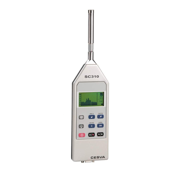
1.3 Description of the SC310 The main components of the SC310 are listed below, the numbers corresponding to those in the outline drawing: 1. ½’’ condenser microphone. The SC310 works with either the C-130 microphone (polarised at 200 V) + PA-13 preamplifier or the C-250 pre-polarised microphone + Pa-14 preamplifier. - Page 15 SC310 User’s Manual...
-
Page 16: Screen
1.4 Screen The current SC310 mode is always indicated in the top right-hand corner of the screen: • Sound Level meter mode • Octave band Spectrum Analyser • One third octave band Spectrum Analyser While the SC310 is measuring, the following information appears at the bottom right of the screen: •... - Page 17 Key to begin or finish a measurement Key to temporarily interrupt a measurement (PAUSE) (while the SC310 is in b. To start recording data into memory (when SC310 is stopped i.e. Key to select the frequency weighting displayed on the...
- Page 18 Key to temporarily interrupt a measurement (PAUSE) (while the SC310 is in d) To begin recording (when SC310 is in Key to return to the previous third octave band Key to go on to the next third octave band...
-
Page 19: Using The Sc310
2.1 First steps This section tells you what to do before starting to use the SC310. 2.1.1 Material and literature The first step is to check that all the material and literature supplied with the SC310 is there: Material: •... -
Page 20: Connecting And Disconnecting The Preamplifier, Using The Extension Cable, The Windscreen And The Outdoor Kit
TIPS: If you are not going to use the SC310 for some time, remove the battery to prevent damage caused by battery leakage. Make sure you always carry spare batteries with you, since you may be measuring somewhere where it isn’t easy to find new ones... - Page 21 [3]. This will damage the sound level meter. NOTE: Extension cables do not have any effect inside the measuring frequency band. In any case, it is necessary to readjust the SC310 when using extension cables. If you have purchased any of the...
-
Page 22: Beginning A Measurement
A few seconds later, the initial screen predetermined in the menu configuration option will appear (see 2.7.5). If the SC310 does not switch on, check that fully charged batteries are fitted or that it is connected to a suitable power supply (see 2.1.2). - Page 23 To identify the current measurement mode, just look at the top right-hand corner of the screen. As long as the SC310 is stopped ( ), you can always sequentially switch between the modes by pressing this key: When you change the mode, a sign identifying it will appear in the screen, during a few seconds.
-
Page 25: Checking The Sc310
SC310 User’s Manual 2.2.3 Checking the SC310 It is advisable to check the SC310 before beginning a measurement, adjust its sensitivity if necessary, and check it again once measurement has terminated. To check the SC310 use the model CB-5 sound calibrator as follows:... -
Page 26: Measuring In Sound Level Meter Mode
If the results of checking the SC310 show a deviation of more than 0.3 dB, adjust the sensitivity as follows: 1) Press the key to finish the measurement process. 2) Do not switch the CB-5 calibrator off; keep it in the calibration position. -
Page 27: Prior Adjustments: Preferential Screen And Integration Time
To configure these parameters, access the SETTINGS MEASURING SOUND LEVEL METER option on the SC310 menu (see 2.7.2) When the previous screen appears, select the function you want to configure, F1, F2, F3 or T, by using the keys, then press... -
Page 28: Beginning A Measurement
), press to stop it. Next, switch the SC310 to sound level meter mode and select the screen you want to see displayed (numeric, graphic, statistical or advanced sound level meter), either from the SC310 menu or by pressing the keys:... - Page 29 The SC310 measures “short” functions (125 ms Functions) but they are not shown in the screen. They only can be seen by making a real time connection between the SC310 and the Capture Studio software or by making a recording with the Sc310 and then downloading the registers to Capture Studio.
- Page 30 In this group of functions, one can find impulsivity detectors, indicators of low spectral content and several functions from international, national or local standards. The SC310, in its basic version (without modulus), has the following functions on this screen:...
-
Page 31: Interrupting Measurement
NOTE: The functions values will be refreshed on the screen each second. 2.3.4 Interrupting measurement When you press the measurement will be temporarily interrupted. The state of measurement indicator will change from While the SC310 is in pause mode ( ) you... -
Page 32: Consulting Measured Data
2.3.5 Consulting measured data While the SC310 is in stop mode ( ) you may consult all the functions measured so far. To consult them, follow the same procedure as described in the section 2.3.3 on displaying data while measurement is in progress. -
Page 33: Beginning Measurement
) press to stop it. Next, set the SC310 in spectrum analyser 1/1 mode and select the screen you want to view (numerical, graphic statistical or NC spectrum analyser 1/1) using the keys: One you have selected the screen, press to set the measurement process in motion. - Page 34 By pressing you access the numerical spectrum analyser 1/1 screen. The SC310 measures "short" functions (125 ms functions), although these are not displayed on the screen. They may be viewed only through the software by means of real-time connection with the sound level meter or by making a recording and subsequently downloading it into a PC.
- Page 35 SC310 User’s Manual • Continuous equivalent sound-pressure level with T integration time for octave bands centred on frequencies 31.5, 63, 125, 250, 500, 1000, 2000, 4000, 8000 and 16000 Hz (without frequency weighting). • Overall continuous equivalent sound-pressure level with T integration time and frequency weightings A, C and Z.
-
Page 36: Stopping Measurement
By pressing you temporarily halt measurement. The state of measurement indicator will change from While the SC310 is in pause mode ( ) you may continue to consult the functions measured until the measurement was temporarily interrupted. To resume measurement, press... -
Page 37: Consulting The Measured Data
2.4.5 Consulting the measured data While the SC310 is not measuring ( ) you may consult all the functions measured so far. To consult them, apply the same formula described in section 2.4.3 to display data while measurement is in progress. -
Page 38: Beginning Measurement
( ) press to stop it. Next, set the SC310 in spectrum analyser 1/3 mode and choose the screen you want to display (numerical or graphic spectrum analyser 1/3) with the following keys: Once you have selected your screen, press to set the measurement process in motion. -
Page 39: Interrupting Measurement
The state of measurement indicator will change from While the SC310 is in pause mode ( ) you may continue to consult the measured functions prior to the temporary interruption of measurement. To resume measurement, press... -
Page 40: Consulting Measured Data
2.7 SC310 menu: Register and setting management This section describes all options accessible from the SC310 menu, a major one of which is memory management and SC310 settings (screens, language, date and time, etc.). When supplied, the SC310 is programmed with an initial setting that allows you to carry out measurements without having to reset the unit prior to beginning measurement. -
Page 41: The Sc310 Menu
• SAVE RESULTS: When you select this option, the SC310 will record the final results of all the functions measured in the memory. The SC310 indicates the register number in which the data has been recorded. For further information, see section 3.1. -
Page 42: Settings
4. 2.7.5 Settings • SETTINGS: This option allows you to set several features of the SC310, such as definition of the initial screen, adjusting the clock/calendar, selecting language or adjusting the sensitivity of the unit. SETTINGS... - Page 43 SETTINGS LANGUAGE This option allows you to select the language in which all the messages and menus of the SC310 will be displayed. To access the option, with the sound meter on press MENU go to SETTINGS with go to LANGUAGE...
-
Page 44: Turning The Sc310 Off
2.8 Turning the SC310 off To turn the SC310 off, make sure no measurement is in progress ( ) and press: 2.9 Warnings and precautions • When you connect or disconnect the microphone, use the strength of your fingers only, never tools. -
Page 45: Advice For Carrying Out Measurements
See section 2.2.3. • If you do not intend to use the SC310 for a long period of time, remove the batteries. • SC310 sound level meter is built to work reliably for a long time. If you do... - Page 46 Measurement range specifications of the sound level meter must be took into account for the measurement of low sound levels. In order to measure sound levels lower than those specified by the lower limit range, the self generated noise from the sound level meter must be took into account.
-
Page 47: Data Registering
SC310 or downloaded into a PC. The memory may also be erased directly from the SC310. Two kinds of registers may be saved in the memory: •... -
Page 48: Carrying Out A Recording
4000, 5000, 6300, 8000 and 10000 Hz Integration time T. Date and time of the beginning of measurement. The SC310 may store a total of 1000 final results, either in sound meter mode or in spectrum analyser 1/1 or 1/3 modes. 3.2 Carrying out a recording A recording consists of conducting a measurement and storing a series of functions with a certain periodicity in the memory. -
Page 49: Kinds Of Recording
The option SETTING RECORDING SOUND METER RECORDING allows you to set the periodicity and functions to be saved in the SC310 memory when a recording is made in sound meter mode. Six possibilities are available: • 1s functions: these save all the functions measured each second: and their maximums and minimums each second plus total measurement time. -
Page 50: Recording In Spectrum Analyser 1/1 Mode
4 years 9 months F1, F2 and F3 are the acoustic functions chosen by the user on the preferential screen. They may be any of those that the SC310 measures in sound meter mode. 3.3.2 Recording in spectrum analyser 1/1 mode... -
Page 51: Recording In Spectrum Analyser 1/3 Mode
Through the SETTING RECORDING SPECTRUM ANALYSER RECORDING option on the SC310 menu you may select the way to store the measured data in the memory: • T functions: once each integration period T has come to an end, the following values are stored in the memory: for each of the one-third octave bands centred on frequencies 20, 25, 31.5,... - Page 52 The storage times for each type of recording correspond to one single recording, until the memory is completely full. The SC310 has enough capacity for up to 1000 registers (final results or recordings) of whatever type. When the built-in memory is full, no more recordings may be made and no more final results saved.
-
Page 53: Circular Memory
This means that as from this moment onwards, when you begin a recording, the SC310 will save data until its memory is full. When this moment comes, it will continue to save data, though deleting the oldest data stored in the memory space prior to beginning the recording. -
Page 54: Data Transfer And Print-Out
To do this, follow the steps detailed below: 1) Connect the AC output of the SC310 to the D.A.T. recorder. 2) Adjust the input gain of the D.A.T. recorder and the output gain of the AC output (see section 2.7.5) to adapt the margin of the measured signal to that of the D.A.T. -
Page 55: Communications Port
PC. It also allows you to transfer the measured functions to a serial printer. When supplied, the SC310 is set by default to communicate with a PC; consequently, the print mode is deactivated. To change this setting, select the PRINTING option from the SC310 menu. -
Page 56: Usb Communications Port
None Stop bits In order to print, the PRINTING option of the SC310 menu must be activated. While it is activated, it will not be possible to carry out serial communication with a PC. When you switch the S310 off, the PRINTING option is automatically deactivated. - Page 57 Sound meter programming (time, sound-meter mode functions, spectrum analyser 1/1 and 1/3, etc.). The SC310 allows you to download recorded data as it is being recorded. In other words, while data is being recorded, it may also be downloaded. This feature, together with the memory setting as a circular buffer, places a limitless memory at your disposal.
-
Page 58: Technical Specifications
5. TECHNICAL SPECIFICATIONS 5.1 Measurement range and L functions Lower limit of the indicator: 0 dB Upper limit of the indicator: 157.0 dB Operating limits are modified by the sensitivity of the microphone. Starting point for level linearity tests 94 dB For C-130 + PA-13: FREQUENCY WEIGHTING Primary Range... - Page 59 SC310 User’s Manual For C-250 + PA-14: FREQUENCY WEIGHTING Primary Range Upper limit 120.0 120.0 120.0 Lower limit 28.2 28.6 34.0 Measurement Range (with nominal sensitivity of microphone) at 1kHz: 137.0 137.0 137.0 Upper limit 130.0 130.0 130.0 Upper limit for crest factor 3: 126.0...
-
Page 60: Detector - Functions L And L
5.2 Detector - Functions L and L For electrical calibration, use the ADM0C130 adapter. Greatest peak-to-peak voltage applicable with the 26 Vpp ADM0C130 adapter Maximum error in the maximum response to a tone burst Function Duration of the tone burst (ms) Maximum error (dB) ±... -
Page 61: Display Update Rates
SC310 User’s Manual 5.5 Display update rates Display update rate When a measurement starts the value of the functions that depend on the integration time T will appear when the integration time T is finished. This value will be updated each second but the changes on the display will not happen until the integration time T is finished. -
Page 62: Ac Output
AC output to audio devices. CESVA only guarantees the correct operating of the equipment when original CESVA accessories are used. Any damage caused to the equipment due to the use of non original CESVA accessories will not be covered by the equipment warranty. 5.8 Octave band filters... -
Page 63: Measurement Range (Octave Band Spectrum Analyser)
SC310 User’s Manual 5.9 Measurement range (octave band spectrum analyser) Function for C-130 + PA-13: Measurement range (with linearity error lower than 0.4 dB): Octave bands with nominal central frequency Lower than 63 Hz: Upper limit: 137 dB Lower limit:... -
Page 64: Measurement Range (One Third Octave Spectrum Analyser)
63 Hz 63.10 Hz 1600 Hz 1584.89 Hz 80 Hz 79.43 Hz 2000 Hz 1995.26 Hz 100 Hz 100.00 Hz 2500 Hz 2511.89 Hz 125 Hz 125.89 Hz 3150 Hz 3162.28 Hz 160 Hz 158.49 Hz 4000 Hz 3981.07 Hz 200 Hz 199.53 Hz 5000 Hz... - Page 65 SC310 User’s Manual Nominal sensitivity: 17.5 mV/Pa in reference conditions Constant pressure to free field correction C-130 Frequency (Hz) Correction (dB) Frequency (Hz) Correction (dB) 31.5 -0.1 2.000 -0.1 4.000 8.000 12.500 16.000 1.000 Corrections of reflections from the case of the sound level meter...
-
Page 66: Diffuse Field Sensitivity (S)
0,50 0,40 0,30 0,20 0,10 0,00 -0,10 -0,20 -0,30 -0,40 -0,50 1000 10000 100000 C-250 ½ ″ prepolarised condenser microphone Polarisation Nominal capacitance 17.0 pF Nominal sensitivity: 46.4 mV/Pa in reference conditions Constant pressure to free field correction C-250 Frequency (Hz) Correction (dB) Frequency (Hz) Correction (dB) -
Page 67: Directivity
SC310 User’s Manual 5.14 Directivity Maximum sensitivity variation at 30º, 90º and 150º from reference direction Vertical plane Frequency (kHz) 30° (dB) 90° (dB) 150º (dB) 0.5 to 1 >1 to 2 >2 to 4 >4 to 8 >8 to 12.5 Maximum sensitivity variation at 30º, 90º... -
Page 68: Effect Of The Accessories On The Microphone
C-130 microphone Directivity (horizontal plane) 1000 2000 4000 0º 0º 0º 340º 350º 10º 20º 340º 350º 10º 20º 340º 350º 10º 20º -1,0 330º -2,0 30º -1,0 -1,0 330º 30º -3,0 330º -2,0 30º -2,0 -4,0 -3,0 -3,0 320º 40º... - Page 69 SC310 User’s Manual Effect of the outdoor kit TK-1000 1000 1995 3981 7943 15849 Effect of the TK-1000 windscreen 1000 1995 3981 7943 15849 Effect of the TK-1000 rain cover 1000 1995 3981 7943 15849 Effect of the TK-1000 Effect of the extension cables The extension cables do not influence into the measuring frequency band.
-
Page 70: Reference Conditions
Classification group Influence of the Magnetic Fields In a magnetic field of 80 A/m (1 oersted) at 50 Hz, the reading will be under 25 dB(A) Sound pressure level at which the SC310 74 dBA meets requirements radiated electromagnetic field. -
Page 71: Vibration Influence
The ones described in chapter the electromagnetic compatibility requirements. 5.29. Configuration for the normal mode of working. Sound level meter mode, L function. Configuration for the reference orientation. The SC310 in vertical position, with SC310 main axis (preamplifier) perpendicular to the field propagation direction... -
Page 72: Preamplifier Connector
5.24 Preamplifier connector The preamplifier is connected to the SC310 by means of LEMO-type connectors: a socket LEMO connector in the sound level meter and a male plug LEMO-type connector in the preamplifier. The pin out of the connectors is the following (exterior view):... -
Page 73: Notes
Serial printer IM003 CESVA only guarantees the correct operating of the equipment when original CESVA accessories are used. Any damage caused to the equipment due to the use of non original CESVA accessories will not be covered by the equipment warranty. -
Page 74: Appendix A: Functions
6. APPENDIX A: Functions 6.1 Function summary table 6.1.1 Sound level meter mode functions Function Frequency Nomenclature Maximum Minimum weighting value value Sound pressure level with fast time weighting AFmax AFmin (Fast) CFmax CFmin ZFmax Zfmin Sound pressure level with slow time ASmax ASmin weighting (Slow) -
Page 75: 1/1 Spectrum Analyser Mode Functions
SC310 User’s Manual Dynamic subtraction of the equivalent A y C continuous sound pressure level with frequency weighting C and A, both with integration time equal to the measurement time. Measurement time Integration time Percentile 1% Percentile 5% Percentile 10%... -
Page 76: Definition Of Functions
6.2 Definition of functions 6.2.1 Sound pressure level with fast and slow time weightings (Fast) RMS value with 125 ms fast exponential averaging, in decibels. (Slow) RMS with 1 s slow exponential averaging, in decibels. EXPONENTIAL 10 ⋅ p(t) AVERAGING ... -
Page 77: Sound Pressure Peak Level
T (a programmable parameter). It is displayed every T time period. In other words, every T time period the SC310 shows the equivalent level of the last T time period. -
Page 78: Percentile Levels
⎛ ⎞ ⎜ ∫ ⎟ ⋅ ⎜ ⎟ ⎝ ⎠ p(t): instantaneous sound pressure reference sound pressure (20 µPa) duration of the measurement 1 second Its relation with the equivalent continuous level is the following one: ⎛ ⎞ ⎜ ⎜ ⎟... -
Page 79: Appendix B: Reverberation Time Module
The module of measurement of the RT is not included with the SC310. It is an optional module and it can be acquired when buying the SC310 or later To incorporate it, you just... -
Page 80: Using The Keyboard
A few seconds later, the initial screen predetermined in the menu configuration option will appear. If the SC310 does not switch on, check that a fully charged battery is fitted or that it is connected to a suitable power supply. -
Page 81: End The Sc310
To switch off the SC310, check there is no measurement in progress ( ) and press: 7.3.5 SC310 menu While there is no measurement in progress ( ) it can be accede to the SC310 menu by pressing: All the menu options are available. - Page 82 You will see that these values will stop oscillating. The initial maximum levels to calculate the RT will be obtained from these values. • From this instant, the SC310 will wait until you interrupt the noise emission. • Stop the noise emission.
-
Page 83: Stopping The Measurement
If during the measurement the sign appears, the SC310 will have not validate the measured values and it can not pass to the next measurement step. If the overload occurs during the decay curve measurement, the measurement will be... -
Page 84: Indicator
7.5.2 Visualizing the third octave bands The SC310 shows the measured data for all the third octave bands in three different sections (50 – 200 Hz), (250 Hz – 1 kHz) and (1,25 kHz – 5 kHz) to accede to its visualization press . -
Page 85: Beginning A Measurement
First of all, check that is no measurement in progress ( ) . If there is, ( ), press to stop it. Next, switch the SC310 to REVERBERATION TIME 1/3 mode and follow the next steps: • Be sure that the noise emission of the sound pressure source is stopped. -
Page 86: Stopping The Measurement
• From this instant, the SC310 will wait until you interrupt the noise emission. • Stop the noise emission. • After a few seconds from the noise emission stop, it will appear at the screen the values of and T and the measurement will finish automatically showing up ( ) on the screen. -
Page 87: Overload Indicator)
The values of the measured functions may be stored in the SC310 internal memory. When the unit is switched off, the data is saved and may be retrieved and displayed directly from the SC310 or transferred to a PC. The memory may be erased directly from the SC310 . 7.6.1 Saving results Once a measurement has been completed ( ), the results may be stored in the memory. -
Page 88: View Register
The SC310 can store more than 7900 final results in REVERBERATION TIME 1/1 mode and more than 2600 in REVERBERATION TIME1/3 mode. 7.6.2 View register This option allows you to display on the screen the final results of the registers stored in the SC310 memory. -
Page 89: Technical Specifications
SC310 User’s Manual 7.7 Technical Specifications 7.7.1 Measurement Range The decay curves are measured from the equivalent levels with integration time: Integration time of the equivalent level 1/1 octave band 1/3 octave band Integration time 50 Hz 40 ms 63 Hz... - Page 90 160 Hz 0,14 s a 17,1 s 200 Hz 0,07 s a 17,1 s 250 Hz 0,07 s a 17,1 s 315 Hz 0,07 s a 17,1 s 400 Hz 0,07 s a 17,1 s 500 Hz 0,07 s a 17,1 s 630 Hz 0,07 s a 17,1 s 800 Hz...
-
Page 91: Estimation Of The Slope Of The Decay Curve
SC310 User’s Manual 5 kHz 0,07 s a 11,4 s 7.7.2 Estimation of the slope of the decay curve The estimation of the slope of the decay curve is automatically achieved from the lineal regression by least square approximation of itself. -
Page 92: Function Summary Table
7.8 Function summary table 7.8.1 Reverberation time mode functions Function Reverberation TimeT Reverberation Time T Sound pressure level of the background noise Initial maximum sound pressure level Time history of the decay curve available (without freq. weighing) All the functions are measured simultaneously Function Reverberation TimeT Reverberation Time T... - Page 93 SC310 User’s Manual below the initial level, until a level 35 dB lower than the initial one. Is the time in seconds that is required for the sound pressure level to decreases 60 dB, calculated on a line from a lineal regression by least squares approximation of a decay curve measured from a 5 dB level below the initial level, until a level 25 dB lower than the initial one.
-
Page 94: Appendix C: Extended Frequency Module
The Extended Frequencial Module for 1/3 octave band analysis of the SC310 it is not included with the SC310. Is an optional module and it can be acquired when buying the SC310 or later. To incorporate it, you just have to contact your official distributor and supply him the serial number of your sound level meter and manage the transaction. -
Page 95: Using The Keyboard For 1/3 Extended Spectrum Analyser Mode
Key to begin or terminate a measurement a) Key to temporarily interrupt a measurement (PAUSE) (while the SC310 is in b) To start recording data into memory (when SC310 is stopped i.e. Key to return to the previous third octave band... -
Page 96: Using The Sc310
If the SC310 does not switch on, check that a fully charged battery is fitted or that it is connected to a suitable power supply. -
Page 97: Measuring In 1/3 Extended Spectrum Analyser Mode
To turn back to the measurement mode press: 8.5 Measuring in 1/3 extended Spectrum Analyser mode In this mode, the SC310 makes a frequency analysis in real time in the one-third octave band from 10 Hz a 20 kHz. Measuring the continuous equivalent sound-pressure level with a... -
Page 98: Functions Display
Next, set the SC310 in extended spectrum analyser 1/3 mode and choose the screen you want to display (numerical or graphic) with the following keys: Once you have selected your screen, press to set the measurement process in motion. 8.5.3 Functions display The SC310 measures all functions simultaneously. - Page 99 SC310 User’s Manual • Continuous equivalent sound-pressure level with 125 ms consecutive integration time (short Leq) in real time for one-third octave bands centred on frequencies 10, 12.5, 16, 20, 25, 31.5, 40, 50, 63, 80, 100, 125, 160, 200, 250, 315, 400, 500, 630, 800, 1000, 1250, 1600, 2000, 2500, 3150, 4000, 5000, 6300, 8000, 10000, 12500, 16000 and 20000 Hz (without frequency weighting).
-
Page 100: Interrupting The Measurement
8.5.5 Consulting measured data While the SC310 is not measuring, ( ) you may consult all the measured functions. To consult them, apply the same procedure as described in the section 8.5.3 on viewing data while measurement is in progress. -
Page 101: Overload Indicator
8.6 Measuring in FFT Narrow Band frequency Analyser Mode This mode of the SC310 sound level meter carries out a FFT frequency analysis in real time. As a result a spectrum of 430 effective lines is obtained, 86 of them are displayed on the screen. -
Page 102: Beginning Measurement
( ) press to stop it. Next, set the SC310 in FFT narrow band frequency analysis and choose the screen you want to display with the following keys: Once you have selected your screen, press to set the measurement process in motion. - Page 103 SC310 User’s Manual To change the chosen FFT line (bar ) press (left) and (right). By pressing you access the FFT narrow band frequency analysis with an interval of visualization x 2.5. Graphic FFT narrow band frequency analysis, zoom x2.5 This screen displays the following information in real time: •...
-
Page 104: Interrupting The Measurement
SC310 or downloaded into a PC. The memory may also be erased directly from the SC310. Two kinds of registers may be saved in the memory: •... -
Page 105: Saving Results
8.7.1 Saving results Once you have completed a measurement ( ), the results may be stored in the memory by selecting the SAVE RESULTS option from the main menu. The SC310 will indicate the register number in which to record the data. -
Page 106: Time Synchronisation
RECORDING SPECTRUM ANALYSER RECORDING option on the SC310 menu you may select the way to store the measured data in the memory: • T functions : once each integration period T has come to an end, the following values are stored in the memory: for each of the one-third octave bands centred on frequencies 10, 12.5, 16,... - Page 107 The storage times for each type of recording correspond to one single recording, until the memory is completely full. The SC310 has enought capacity for up to 1000 registers (final results or recordings) of whatever type. When the built-in memory is full, no more recordings may be made and no more final results saved.
-
Page 108: Circular Memory
This means that as from this moment onwards, when you begin a recording, the SC310 will save data until its memory is full. When this moment comes, it will continue to save data, though deleting the oldest data stored in the memory space prior to beginning the recording. -
Page 109: Technical Specifications
SC310 User’s Manual 8.10 Technical specifications 8.10.1 Third octave band filters Type 1 filters in compliance with IEC 61260:1995/A1:2001. Frequency evaluation system Base 10 Reference attenuation 0 dB Operative linearity range same as the measurement range Third octave band nominal central frequencies... -
Page 110: Measurement Range (One Third Octave Spectrum Analyser)
8.10.2 Measurement range (one third octave spectrum analyser) Function for C-130 + PA-13: Measurement range (with linearity error lower than 0.4 dB): One third octave bands with nominal central frequency From 10 Hz to 16 Hz: Upper limit: 137 dB Lower limit: 39 dB From 20 Hz to 31.5 Hz: Upper limit:... -
Page 111: Function Summary Table
SC310 User’s Manual 8.11 Function summary table 8.11.1 1/3 Extended Spectrum analyser mode functions Function Name TOTAL 12.5 31.5 Equivalent continuous A, C, Z sound pressure level with integration time T Function 1000 1250 1600 Equivalent continuous sound pressure level with... -
Page 112: Fft Narrow Band Frequency Analyser
8.12 FFT narrow band frequency analyser Time window Hanning No. of lines Analysis Resolution 46.5 Hz Frequency range displayed on Zoom x1 20 kHz the screen Zoom x2.5 8 kHz Zoom x5 4 kHz Dynamic measurement range > 80 dB... -
Page 113: Apendix D: Dosimeter Module For The Assessment Of Noise At Workplace
The dosimeter module for the assessment of noise at workplace is not included with the SC310. It is an optional module and it can be acquired when buying the SC310 or later. To incorporate it, you just have to contact your official distributor and supply him the serial number of your sound level meter and manage the transaction. -
Page 114: Using The Keyboard For The Dosimeter Mode
A few seconds later, the initial screen predetermined in the configuration menu option will appear. If the SC310 does not switch on, check that fully charged batteries are fitted or that it is connected to a suitable power supply. -
Page 115: Accessing To The Dosimeter Mode
User’s Manual 9.3.2 Accessing to the Dosimeter mode Switch on the SC310 and check there is no measurement running ( ), press sequentially the key until appears the title “DOSIMETER”. Then will appear the dosimeter mode on the screen. This mode can be identified by the indication that will appear at the right upper corner of the screen. -
Page 116: Beginning Measurement
First of all, ensure that the sound level meter has no measuring process in progress ( ). If it has ( ), press to stop it. Next, set the SC310 in dosimeter mode and choose the screen you want to display (numeric, 1/1 Spectrum analyser or graphic), with the following keys:... -
Page 117: Function Display
9.4.3 Function display The SC310 measures all functions simultaneously. Described below are the different ways of displaying the acoustic functions for the assessment of noise at workplace while measurement is taking place. If you change the kind of display (screen) or the octave band selected (spectrum analyser screen), measurement will continue uninterrupted. - Page 118 • Projected daily noise exposure level (L EX,8h p • Projected sound exposure (E • Projected noise dose (DOSE • Measurement time (t) and projected time (t To return to the previous screen press When a register recovered from the memory is displayed on the screen the sound level meter uses the L criterion level and the t projection time configured.
-
Page 119: Interrupting The Measurement
The SC310 can record in the internal memory the values of the measured functions. When switching on the equipment, the recorded data will not be lost and can be retrieved and displayed directly from the SC310 or transmitted to a PC. The memory can be erased directly from the SC310 . -
Page 120: Making A Recording
During the recording process, the measurement in progress icon ( ) will flicker. 9.5.3 Time synchronisation The SC310 allows you to begin recording at the o’clock (hh:00:00). To access this option, select SETTING RECORDING TIME SYNCHRONISATION from the SC310 menu. -
Page 121: Kinds Of Recording
SC310 User’s Manual 9.5.4 Kinds of recording The dosimeter mode stores the following information: T Functions: once each integration interval T has come to an end, the following values are stored in the memory: • Equivalent continuous sound pressure level with frequency weighting A (L •... -
Page 122: Circular Memory
The storage times for each type of recording correspond to one single recording, until the memory is completely full. The SC310 has enough capacity for up to 1000 registers (final results or recordings) of any kind. When the built-in memory is full, no more recordings can be made and no more final results saved. -
Page 123: Technical Specifications
SC310 User’s Manual 9.8 Technical specifications. The technical features of the measurement parameters are according with chapter 5 of this manual 9.8.1 Standards Standards IEC 61672 type 1, IEC 60804:00 type 1, IEC 60651:01 type 1 DIRECTIVE 2003/10/EC OF THE EUROPEAN PARLIAMENT AND OF THE COUNCIL of... -
Page 124: Apendix E: Module For Vibration Measurements
The Human exposure to whole-body vibration in buildings module is not included with the SC310. It is an optional module and it can be acquired when buying the SC310 or later. In order to acquire it, you just have to contact your official distributor and supply him the serial number of your sound level meter. -
Page 125: Vibration Measurement Module Activation
BNC type connector. If you do not have it please contact your distributor. 10.1.2 Vibration measurement module activation To activate the Module for vibration measurements (VT) in the firmware of the SC310, follow the next steps: • Insert in the CD-ROM drive the CD that you have received. The activation program ‘SC310 VT module Activator’... -
Page 126: If You Want To Connect A Different Accelerometer
• Connect the accelerometer to the PA001 preamplifier, introducing the BNC male connector from the accelerometer plug into the BNC female connector from the preamplifier. To introduce it you should make the groove coincide from both connectors. Once it is introduced, turn the external ring from the accelerometer until this gets fixed. -
Page 127: Using The Keyboard For The Vibration Mode
Key to begin and to finish a measurement. c) Key to temporarily interrupt a measurement (PAUSE) (while the SC310 is in d) To start recording data into memory (when SC310 is stopped i.e. Key to return to the previous one-third octave band or one-... -
Page 128: Using The Sc310
A few seconds later, the initial screen predetermined in the configuration menu option will appear. If the SC310 does not switch on, check that fully charged batteries are fitted or that it is connected to a suitable power supply. -
Page 129: Measuring In Vibration Mode
To go back to the measurement mode press: 10.5 Measuring in Vibration mode In this mode, the SC310 makes an analysis in real time of the overall acceleration and frequential acceleration in third octave band from 1Hz to 80Hz. To evaluate the frequential parameters, it is measured the RMS value of the averaged acceleration during the evaluation time T that can be programmed. -
Page 130: Prior Adjustments: Evaluation Time
3) Select the model of the accelerometer. In this way the sensitivity of the SC310 will be adjust to the nominal sensitivity of the selected accelerometer: AC001 S = 100 mV/g, or AC005 S = 500 mV/g or AC006 S = 1000 mV/g If you have the CV111 CESVA calibrator for vibration you can adjust the sensitivity value in a more precise way by following the next steps. -
Page 131: Beginning Measurement
), press to stop it. Next, set the SC310 in vibration mode and choose the screen you want to display (Graphic Spectrum analyser 1/3 + K, Numeric Spectrum Analyser 1/3 or Numeric overall analyser with weighted), with the following keys: Once you have selected your screen, press to start the measurement process. - Page 132 The SC310 measures “short” functions (Functions 125 ms) but are not shown on the screen. Only can be seen through the Capture Studio, through a real time connection with the SC310 or doing a recording and downloading the data to the PC. These functions are: Averaged acceleration (RMS) with evaluation time 125 ms (Short) in real time for one third octave band centred in the frequencies 1, 1.25, 1.6, 2, 2.5, 3.15, 4, 5, 6.3, 8, 10,...
- Page 133 SC310 User’s Manual • Numeric average acceleration (RMS) with evaluation time T, in real time for the one third octave band centred in the frequencies 1, 1.25, 1.6, 2, 2.5, 3.15, 4, 5, 6.3, 8, 10, 12.5, 16, 20, 25, 31.5, 40, 50, 63 and 80 Hz (without frequency weighting) expressed in m/s...
-
Page 134: Interrupting The Measurement
10.6 Measuring FFT Narrow Band Frequency Analysis This mode of the SC310 sound level meter carries out a FFT frequency analysis in real time. As a result a spectrum of 430 effective lines is obtained, 86 of them are displayed in the screen. -
Page 135: Prior Adjustments: Sensitivity
ACCELEROMETER from the SC310 menu. 2) It appears the next screen: 3) Select the model of the accelerometer. In this way the sensitivity of the SC310 will be adjust to the nominal sensitivity of the selected accelerometer: AC001 S = 100... -
Page 136: Prior Adjustments: Evaluation Time
ACCELEROMETER ADJUSTS from the SC310 menu 6) The acceleration level measured by the SC310 will appear on the screen, this acceleration level is measured without frequency weighting: 7) Verify that the reading value is 140 dB (corresponding to the nominal acceleration value). -
Page 137: Beginning The Measurement
Then, ensure that the sound level meter has no measuring process in progress ( ). If it has ), press to stop it. Next, set the SC310 in FFT narrow band frequency analysis for vibration and choose the screen you want to display, with the following keys: Once you have selected your screen, press to start the measurement process. - Page 138 FFT Narrow band frequency analysis screen, zoom x1 This screen shows, in real time, the next information: • Visualization of the whole frequency range analysis (0 Hz – 1 kHz) in only one screen. The line with the greatest value from each group of 5 lines of the frequency analysis is showed (the frequency analysis consists on 430 effective lines and 86 display lines.
-
Page 139: Interrupting The Measurement
To resume measurement, press By pressing you stop the measurement. The state of measurement indicator will change from 10.6.6 Consulting measured data While the SC310 is not measuring ( ), you may consult all the measured functions. -
Page 140: Overload Indicator
The SC310 can record in the internal memory the values at the measured functions. When turning on the equipment, the recorded data will not be lost and can be retrieved and displayed directly from the SC310 or transmitted to a PC. The memory can be erased directly from the SC310 . -
Page 141: Making A Recording
During the recording process, the measurement in progress icon ( ) will flicker. 10.7.3 Time synchronisation The SC310 allows you to begin recording on the hour (hh:00:00). To access this option, select SETTING RECORDING TIME SYNCHRONISATION from the SC310 menu. - Page 142 VDV: Vibration Dose Value. With frequency weighting W and evaluation time 1,75 T. Expressed in m/s Remark the type of recording that we have when programming T=t. This way, we will have a register each second where it is saved the time history of the averaging. •...
-
Page 143: Circular Memory
The storage times for each type of recording correspond to one single recording, until the memory is completely full. The SC310 has enought capacity for up to 1000 registers (final results or recordings) of any kind. When the built-in memory is full, no more recordings can be made and no more final results saved. -
Page 144: View The Register
SC310 menu. By pressing , the SC310 allows you to select the register you want to view. The screen will display an index of all the registers stored in the memory (register number + date and time when the measurement process began). -
Page 145: Technical Specifications
SC310 User’s Manual 10.10 Technical specifications 10.10.1 One third octave band filters Type 1 filters according to IEC 61260:1995/A1:2001. Frequency evaluation system Base 10 Reference attenuation 0 dB Operative linearity range Same as the measurement range Third octave band nominal central frequencies... -
Page 146: Standards
Frequency weighting W Frequency Frequency weighting W Nominal Real Factor 0.1995 Hz 0.0629 -24.02 0.25 0.2512 Hz 0.0994 -20.05 0.315 0.3162 Hz 0.156 -16.12 0.3981 Hz 0.243 -12.29 0.5012 Hz 0.368 -8.67 0.63 0.6310 Hz 0.530 -5.51 0.7943 Hz 0.700 -3.09 1.000 Hz 0.833... -
Page 147: Function Summary Table
SC310 User’s Manual Measurement standards ISO 2631-1 ISO 2631-2 10.11 Function summary table 10.11.1 Vibration mode functions Function Weigh. Name TOTAL 1.25 3.15 Average acceleration with evaluation time T [m/s Average acceleration level with evaluation time T [dB ref 10 Function 12.5... -
Page 148: Function Definitions
10.12 Function definitions 10.12.1 Average acceleration with frequency weighting W evaluation time T R.M.S. value of acceleration expressed in m/s , defined by: ⎛ ⎞ ⎜ ∫ ⎟ ⎜ ⎟ ⎝ ⎠ (t): instantaneous acceleration based on the time t and with frequency weighting W , in m/s duration of the measurement (evaluation) -
Page 149: Vibration Dose Value
SC310 User’s Manual ⎡ ⎤ ⎛ ⎞ ζ ζ τ ζ ⎢ ⋅ ⎥ - (t ⎜ ⎟ MTVV ∫ τ ⎝ ⎠ ⎢ ⎥ ∞ ⎣ ⎦ instantaneous acceleration based on the time ξ and with frequency (ξ): weighting W... -
Page 150: Narrow Band Frequency Analysis For Vibration
10.12.8 Narrow band frequency analysis for vibration Time window Hanning No. of lines Analysis Resolution 2.3 Hz Frequency range displayed on Zoom x1 1 kHz the screen Zoom x2.5 400 Hz Zoom x5 200 Hz Dynamic measurement range > 80 dB... - Page 152 Villar, 20, bajos – 08041 BARCELONA (ESPAÑA) Tel. (+34) 934 335 240 – FAX (+34) 933 479 310 e-mail: info@cesva.com www.cesva.com...
Need help?
Do you have a question about the SC310 and is the answer not in the manual?
Questions and answers