Table of Contents
Advertisement
Quick Links
Advertisement
Table of Contents

Related Manuals for CESVA SC260


Summary of Contents for CESVA SC260
- Page 1 SC260 Sound Level Meter Spectrum Analyser User’s Manual M_SC260_v0008_20171024_EN...
-
Page 3: Table Of Contents
ENGLISH CONTENTS 1. GENERAL FEATURES ..................... 5 1.1 Operating modes and functions ..................5 1.2 Main features of the SC260 ..................7 1.3 Description of the SC260....................9 1.4 Screen .........................11 1.5 Using the keyboard .....................11 2. USING THE SC260 ......................14 2.1 First steps ........................14... - Page 4 3. DATA REGISTRATION ....................40 3.1 Saving results ......................40 3.2 Making a recording ......................41 3.2.1 Time synchronisation ..................41 3.3 Kinds of recording .......................42 3.3.1 Recording in sound level meter mode ...............42 3.3.2 Recording in spectrum analyser 1/1 mode ............43 3.3.3 Recording in spectrum analyser 1/3 mode ............44 3.3.4 Circular memory ....................46 3.4 Viewing registers ......................46...
- Page 5 Percentile levels ....................67 7. APPENDIX B: Reverberation Time Module ..............68 7.1 Activation of the Reverberation Time Module ..............68 7.2 Using the keyboard .....................69 7.3 Using the SC260 ......................69 7.3.1 Switching on the SC260 ..................69 7.3.2 Accessing the Reverberation Time Mode 1/1 ...........69 7.3.3...
- Page 6 9.3 Using the SC260 ......................99 9.3.1 Switching on the SC260 ..................99 9.3.2 Accessing the Dosimeter mode ............... 100 9.3.3 Turning off the SC260 ..................100 9.3.4 SC260 Menu ....................100 9.4 Measuring in dosimeter mode ................... 100 9.4.1 Prior adjustments .................... 100 9.4.2...
-
Page 7: General Features
American standards ANSI S1.4 and ANSI S1.43. The SC260 is also a spectrum analyser measuring in real time and in one third octave bands and octave bands*, with class 2 filters, which comply with IEC 61260 and EN61260. It also complies with ANSI S1.11. - Page 8 T interval of the sound pressure level with time averaging ‘F’ and frequency weighting A. The SC260 also displays the following acoustic functions: The subtraction of the equivalent continuous sound pressure level with time averaging ‘I’...
-
Page 9: Main Features Of The Sc260
The functions in italics are measured by the SC260 but are not shown on its screen. The way to get the results of these functions is to make a real time measurement with the Capture Studio software application or making a recording and downloading the results to a PC with the help of Capture Studio (see chapter 4). - Page 10 The SC260 has multiple language support and once a language is selected, it will remain selected even if the unit is turned OFF (see paragraph 2.7.5) The SC260 stores in its memory the time and date of the last time the sensitivity was modified. (See 2.2.3) ...
-
Page 11: Description Of The Sc260
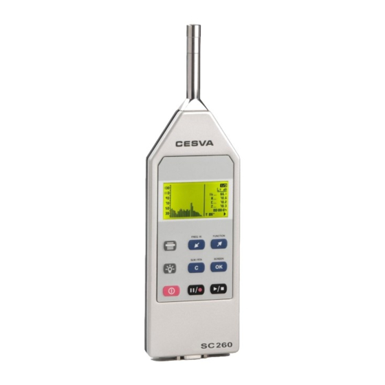
SC260 User’s Manual 1.3 Description of the SC260 The main components of the SC260 are listed below, the numbers corresponding to those in the outline drawing: 1. ½’’ condenser microphone. The SC260 works with the P-05 microphone. This kind of microphone is removable. To move it away from the SC260 body, use the CNRITV cable. -
Page 13: Screen
SC260 User’s Manual 1.4 Screen The SC260 mode in use is always indicated in the top right-hand corner of the screen: Sound Level meter mode Octave band Spectrum Analyser One-third octave band Spectrum Analyser While the SC260 is measuring, the following information appears in the bottom right-hand corner of the screen: ... - Page 14 Key to begin or finish a measurement Key to temporarily interrupt a measurement (PAUSE) (while the SC260 is in b. To start recording data into memory (when SC260 is stopped i.e. Key to select the frequency weighting displayed on the...
- Page 15 Key to temporarily interrupt a measurement (PAUSE) (while the SC260 is in d) To begin recording (when SC260 is in Key to return to the previous third octave band Key to go on to the next third octave band...
-
Page 16: Using The Sc260
2.1 First steps This section describes what to do before starting to use the SC260. 2.1.1 Material and literature The first step is to check that all the material and literature supplied with the SC260 is there: Material: SC260 sound level meter ... -
Page 17: Connecting And Disconnecting The Preamplifier, Using The Extension Cable, The Windscreen And The Outdoor Kit
The SC260 microphone is completely detachable. This allows it to be moved it away from the sound level meter and user. In this way the SC260 can be operated far from the place of measurement, thereby avoiding possible interference. To do this, use the CNRITV extension cable. - Page 18 To detach the microphone from the sound level meter, simply unscrew it by hand (no tools). To reconnect the microphone to the sound level meter, simply screw it back on. NOTE: accepts no responsibility for any operations by unauthorised personnel, which will be sufficient grounds for voiding the warranty.
-
Page 19: Beginning A Measurement
A few seconds later, the initial screen predetermined in the menu configuration option will appear (see 2.7.5). If the SC260 does not switch on, check that fully charged batteries are fitted or that it is connected to a suitable power supply (see 2.1.2). -
Page 21: Checking The Sc260
SC260 User’s Manual 2.2.3 Checking the SC260 It is advisable to check the SC260 before beginning a measurement, adjust its sensitivity if necessary, and check it again once the measurement has terminated. To check the SC260 use the model CB006 or CB004 sound calibrator as... -
Page 22: Measuring In Sound Level Meter Mode
If the results of checking the SC260 show a deviation of more than 0.3 dB, adjust the sensitivity as follows: 1) Press the key to finish the measurement process. 2) Do not switch the CB006/CB004 calibrator off; keep it in the calibration position. - Page 23 This integration is carried out in consecutive intervals of duration T. To set these parameters, access the SETTINGS MEASURING SOUND LEVEL METER option on the SC260 menu (see 2.7.2) When the above screen appears, select the function to be set, F1, F2, F3 or T, by using the...
-
Page 24: Beginning A Measurement
First of all, check that there is no measurement in progress ( ). If there is, ( ), press to stop it. Next, switch the SC260 to sound level meter mode and select the screen to be displayed (numeric, graphic, statistical or advanced sound level meter), either from the SC260 menu or by pressing the keys: Once the screen has been selected, press to start the measurement process. - Page 25 The SC260 measures “short” functions (125 ms Functions) but they are not shown on the screen. They only can be seen by making a real time connection between the SC260 and the Capture Studio software or by making a recording with the SC260 and then downloading the registers to Capture Studio.
- Page 26 In this group of functions are impulsivity detectors, indicators of low spectral content and several functions for international, national or local standards. The SC260, in its basic version (without modules), has the following functions on this screen: Name Function The equivalent continuous sound pressure level with time averaging ‘I’...
-
Page 27: Interrupting A Measurement
2.3.5 Consulting the data measured While the SC260 is in stop mode ( ) all the functions measured so far may be consulted. This is done the same way as described in section 2.3.3 for displaying data while a... -
Page 28: Measuring In Spectrum Analyser Mode 1/1
125, 250, 500, 1000, 2000, 4000, 8000 and 16000 Hz (without frequency weighting), and Overall values with all frequency weightings (A, C and Z). The SC260 also measures the peak sound pressure level for the consecutive integration time T with all frequency weightings (A, C and Z). -
Page 29: Beginning A Measurement
) press to stop it. Next, set the SC260 to spectrum analyser 1/1 mode and select the screen to be displayed (numerical, graphic statistical or NC spectrum analyser 1/1) using the keys: One the desired screen has been selected, press to start the measurement process. - Page 30 (right). The numerical spectrum analyser 1/1 screen is accessed by pressing The SC260 measures "short" functions (125 ms functions), although these are not displayed on the screen. They may be viewed only through the software by means of real-time connection with the sound level meter or by making a recording and subsequently downloading it on to a PC.
- Page 31 SC260 User’s Manual The equivalent continuous overall sound pressure level with T integration interval and with frequency weightings A, C and Z. The maximum of the peak sound pressure level of the T integration interval with frequency weighting (A, C and Z).
-
Page 32: Stopping A Measurement
2.4.5 Consulting the data measured All the functions measured so far may be consulted while the SC260 is not measuring ( ). This is done in the same way as described in section 2.4.3 on displaying data while a... -
Page 33: Measuring In Spectrum Analyser 1/3 Mode
The spectrum analyser 1/3 mode has been designed to measure spectral contents with one- third octave definition. The SC260 conducts a frequency analysis in bands from 20 Hz to 10 kHz. This analysis is carried out in real time for all bands and throughout the entire dynamic range of measurement (without scale changes), measuring the continuous equivalent sound- pressure level with integration time programmable from 1 second to 99 hours. -
Page 34: Beginning A Measurement
First of all, check that there is no measurement in progress ( ). If there is ( ) press to stop it. Next, set the SC260 in spectrum analyser 1/3 mode and choose the screen to be displayed (numeric or graphic spectrum analyser 1/3) with the following keys: Once the screen has been selected, press to start the measurement process. -
Page 35: Interrupting A Measurement
2.5.5 Consulting the data measured While the SC260 is not measuring, ( ) all the functions measured may be consulted. This is done the same way as described in section 2.5.3 on displaying data while a measurement is in progress. -
Page 36: Overload Indicator
SC260 settings (screens, language, date and time, etc.). When supplied, the SC260 is programmed with an initial setting that allows you to carry out measurements without having to reset the unit prior to beginning measurement. -
Page 37: The Sc260 Menu
SAVE RESULTS: When this option is selected, the SC260 will record the final results of all the functions measured in the memory. The SC260 indicates the register number in which the data has been recorded. For further information, see section 3.1. -
Page 38: Settings
2.7.5 Settings SETTINGS: This option allows several features of the SC260 to be set, such as definition of the initial screen, adjustment of the clock/calendar, the language or the sensitivity of the unit. SETTINGS MEASURING SOUND LEVEL METER... - Page 39 This option allows the gain of this output to be adjusted: 0 dB or 40 dB. SETTINGS LANGUAGE This option allows the language in which all the messages and menus of the SC260 will be displayed to be selected. To access the option, with the sound go to SETTINGS with ...
-
Page 40: Turning The Sc260 Off
Remove the batteries if the SC260 is not going to be used for a long period of time,. SC260 sound level meter is built to work reliably for a long time. I Should... -
Page 41: Advice For Carrying Out Measurements
SC260 User’s Manual This equipment can only work with the accessories described in the accessories section. In the case of different accessories being used, resulting in a failure in the equipment, will accept no responsibility for this failure. In this case the equipment will lose its warranty 2.10 Advice for carrying out measurements... -
Page 42: Data Registration
The SC260 built-in memory registers the values of the functions measured. When the unit is switched off the data is saved and may be retrieved and displayed directly on the SC260 or downloaded onto a PC. The memory may also be erased directly from the SC260. -
Page 43: Making A Recording
4000, 5000, 6300, 8000 and 10000 Hz Integration time T. Date and time of the beginning of measurement. The SC260 may store a total of 1000 final results, either in sound meter mode or in spectrum analyser 1/1 or 1/3 modes. 3.2 Making a recording A recording consists of conducting a measurement and storing a series of functions in the memory with a certain periodicity. -
Page 44: Kinds Of Recording
3.3.1 Recording in sound level meter mode The option SETTING RECORDING SOUND METER RECORDING sets the periodicity and functions to be saved in the SC260 memory when a recording is made in sound meter mode. Six possibilities are available: ... -
Page 45: Recording In Spectrum Analyser 1/1 Mode
4 years 9 months F1, F2 and F3 are the acoustic functions chosen by the user on the preferred screen. They may be any of those that the SC260 measures in sound level meter mode. 3.3.2 Recording in spectrum analyser 1/1 mode Recording in spectrum analyser 1/1 mode may be set through the SETTINGS ... -
Page 46: Recording In Spectrum Analyser 1/3 Mode
3.3.3 Recording in spectrum analyser 1/3 mode Through the SETTING RECORDING SPECTRUM ANALYSER RECORDING option on the SC260 menu the way to store the measured data in the memory may be selected: T functions: once each integration period T has come to an end, the following values are stored in the memory: for each of the one-third octave bands centred on frequencies 20, 25, 31.5,... - Page 47 The storage times for each type of recording correspond to one single recording, until the memory is completely full. The SC260 has capacity for up to 1000 registers (final results or recordings) of any type. When the built-in memory is full, no more recordings may be made and no more final results saved.
-
Page 48: Circular Memory
This means that from this moment onwards, when a recording begins the SC260 will save data until its memory is full. When this moment comes, it will continue to save data, though deleting the oldest data stored in the memory space prior to beginning the recording. -
Page 49: Data Transfer And Print-Out
The SC260 AC output also enables the user to listen to the signal being measured and ascertain whether it is being influenced by noises other than those being measured. -
Page 50: Communications Port
PC. It also enables the functions measured to be transferred to a serial printer. When supplied, the SC260 is set by default to communicate with a PC; consequently, the print mode is deactivated. To change this setting, select the PRINTING option from the SC260 menu. -
Page 51: Usb Communications Port
None Stop bits In order to print, the PRINTING option of the SC260 menu must be activated. While it is activated, it will not be possible to carry out serial communication with a PC. When the SC260 is switched off, the PRINTING option is automatically deactivated. - Page 52 Sound level meter programming (time, SLM mode functions, spectrum analyser 1/1 and 1/3, etc.) The SC260 enables data to be downloaded as it is being recorded. This feature, together with the memory setting as a circular buffer, makes a limitless memory available. It is simply necessary to periodically download data before the memory reaches its maximum capacity.
-
Page 53: Technical Specifications
SC260 User’s Manual 5. TECHNICAL SPECIFICATIONS 5.1 Measurement range and L functions Starting point for level linearity tests 94 dB FREQUENCY WEIGHTING Electric Measurement Range (with nominal sensitivity of the microphone) at 1kHz: Upper limit 137.0 137.0 137.0 Upper limit for crest factor 3: 130.0... -
Page 54: Detector - Functions L And L
5.2 Detector - Functions L and L For electrical calibration, use the adapter. ADM0P05 Greatest voltage applicable with the ADM0P05 adapter 26 Vpp Maximum error in the maximum response to a tone burst Function Duration of the tone burst (ms) Maximum error (dB) ±... -
Page 55: Display Update Rates
SC260 User’s Manual 5.5 Display update rates Display update rate When a measurement starts the value of the functions that depend on the integration time T will appear when the integration time T is finished. This value will be updated every second but the changes on the display will not show until the integration time T is finished. -
Page 56: Ac Output
5.7 AC output Frequency weighting: Linear Sensitivity at 137 dB and 1 kHz (Gain: 0 dB): 3.8 Vrms (max) Upper limit: 7 Vpeak 100 Output impedance: 0 or 40 dB 0.2 dB Gain Central pin AC signal Connector with 1.3 mm central pin 5.8 Octave band filters Frequency evaluation system... -
Page 57: Measurement Range (Octave Band Spectrum Analyser)
SC260 User’s Manual 5.9 Measurement range (octave band spectrum analyser) Function for P-05: Measurement range (with linearity error lower than 0.4 dB): Octave bands with nominal central frequency Lower than 63 Hz: Upper limit: 137 dB Lower limit: 30 dB... -
Page 58: Measurement Range (One-Third Octave Spectrum Analyser)
5.11 Measurement range (one-third octave spectrum analyser) Function for P-05: Measurement range (with linearity error lower than 0.4 dB): Octave bands with nominal central frequency Lower than 40 Hz: Upper limit: 137 dB Lower limit: 40 dB From 40 Hz to 100 Hz: Upper limit: 137 dB Lower limit: 32 dB... -
Page 59: Effect Of The Accessories On The Microphone
SC260 User’s Manual 5.14 Effect of the accessories on the microphone Corrections for the effects of the PVM-05 windscreen Frequency (Hz) Correction microphone P-05 (dB) 1000 0,00 1259 0,10 1585 0,20 1995 0,30 2512 0,35 3162 0,30 3981 0,25 5012... -
Page 60: Reference Conditions
5.15 Reference conditions Type of sound field: Free Reference direction Perpendicular to the microphone diaphragm Microphone Reference point Central point of the microphone diaphragm 94 dB (referred to 20 Pa) Reference sound pressure level: Reference frequency: 1 kHz Reference temperature: 23 °C Reference relative humidity: 50 %... -
Page 61: Electromagnetic Compatibility
Operating mode and position that produces the Sound level meter mode, L greatest radio frequency. function. SC260 vertical, with the main axis of the SC260 (preamplifier) perpendicular to the field propagation direction with vertical polarization. With all leads connected, and with the... -
Page 62: Batteries & External Supply
5.21 Batteries & external supply Battery Two AA sized (LR6) 1.5 V batteries Typical battery life with continuous use: Sound Level Meter 13:30 hours Spectrum Analyser 1/1 12:30 hours Spectrum Analyser 1/3 9:30 hours The typical battery life with the display light on can be reduced by 50% with respect to the values above External Supply Voltage input range... -
Page 63: Standards
Should your SC260 cease to comply with any of these specifications, contact the nearest official service technicians, who will gladly check, adjust and/or repair it . The SC260 should be calibrated and tested by a competent entity, at least, once a year. -
Page 64: Accessories
Charger for 1,5 V 2600 mA batteries CP015 CESVA only guarantees the correct operation of the equipment when original CESVA accessories are used. Any damage caused to the equipment due to the use of non original CESVA accessories will not be covered by the equipment warranty. -
Page 65: Appendix A: Functions
SC260 User’s Manual 6. APPENDIX A: Functions 6.1 Function summary table 6.1.1 Sound level meter mode functions Function Frequency Nomenclature Maximum Minimum weighting value value Sound pressure level with fast time weighting AFmax AFmin (Fast) CFmax CFmin ZFmax Zfmin Sound pressure level with slow time... -
Page 66: 1/1 Spectrum Analyser Mode Functions
Dynamic subtraction of the equivalent A y C continuous sound pressure level with C and A frequency weighting, both with integration time equal to the measurement time. Measurement time Integration time Percentile 1% Percentile 5% Percentile 10% Percentile 50% Percentile 90% Percentile 95% Percentile 99% -: unavailable... -
Page 67: Definition Of Functions
SC260 User’s Manual 6.2 Definition of functions 6.2.1 Sound pressure level with fast and slow time weightings (Fast) RMS value with 125 ms fast exponential averaging, in decibels. (Slow) RMS with 1 s slow exponential averaging, in decibels. ... -
Page 68: Sound Pressure Peak Level
The equivalent L level is the equivalent level corresponding to integration time T (a programmable parameter). Every T interval the SC260 shows the equivalent level of the last T interval. -
Page 69: Sound Exposure Level (Sel)
SC260 User’s Manual 6.2.5 Sound exposure level (SEL) (SEL) Sound exposure level. This is the sound level that, kept constant for 1 second, presents energy equivalent to the energy accumulated throughout the entire measurement, in decibels. ... -
Page 70: Appendix B: Reverberation Time Module
The RT measurement module is not included with the SC260. It is an optional module and it can be acquired when buying the SC260 or later To incorporate it simply contact an official distributor and supply him the serial number of the sound level meter. -
Page 71: Using The Keyboard
A few seconds later, the initial screen predetermined in the menu setting option will appear. If the SC260 does not switch on, check that a fully charged battery is fitted or that it is connected to a suitable power supply. -
Page 72: Switching Off The Sc260
7.3.4 Switching off the SC260 To switch off the SC260, check there is no measurement in progress ( ) and press: 7.3.5 SC260 menu While there is no measurement in progress ( )the SC260 menu can be accessed by pressing: All the menu options are available. - Page 73 You will see that these values will stop oscillating. The initial maximum levels to calculate the RT will be obtained from these values. From this instant, the SC260 will wait until the noise emission is interrupted. Stop the noise emission.
-
Page 74: Stopping The Measurement
7.4.4 Overload indicator The SC260 has an overload indicator. If during the measurement an overload has occurred, the sign ^ will appear before the value of the function affected. While there is an overload, the sign will appear in the bottom right-hand corner of the screen. -
Page 75: Indicator
7.5.2 Displaying the one-third octave bands The SC260 shows the data measured for all the one-third octave bands in three different sections (50 – 200 Hz), (250 Hz – 1 kHz) and (1,25 kHz – 5 kHz). To access the display press . -
Page 76: Beginning A Measurement
First of all, check that there is no measurement in progress ( ) . If there is, ( ), press to stop it. Next, switch the SC260 to reverberation time 1/3 mode and proceed as follows: Make sure that the sound pressure source is stopped. -
Page 77: Stopping The Measurement
( )showing on the screen. The SC260 also measures the decay curves of the sound pressure level, but this only can be displayed by recording the final result of the measurement and downloading these data to the computer using the CAPTURE Studio software application. -
Page 78: Indicator
The values of the functions measured may be stored in the SC260 internal memory. When the unit is switched off, the data is saved and may be retrieved and displayed directly from the SC260 or transferred to a PC. The memory may be erased directly from the SC260. 7.6.1 Saving results Once a measurement has been completed ( ), the results may be stored in the memory. -
Page 79: Technical Specifications
SC260 User’s Manual The SC260 allows the required register to be selected, using the keys, with index appearing on-screen showing all the registers stored in the memory (register number + date and time of the beginning of the measurement process). - Page 80 The range of measurement for the T and T functions is: 1/1 octave band 1/3 octave band 50 Hz 0.48 s a 17.1 s 63 Hz 0.48 s a 17.1 s 80 Hz 0.48 s a 17.1 s 100 Hz 0.24 s a 17.1 s 125 Hz 0.24 s a 17.1 s...
-
Page 81: Estimation Of The Slope Of The Decay Curve
SC260 User’s Manual 800 Hz 0.12 s a 11.4 s 1 kHz 0.12 s a 11.4 s 1.25 kHz 0.12 s a 11.4 s 1,6 kHz 0.12 s a 11.4 s 2 kHz 0.12 s a 11.4 s 2.5 kHz 0.12 s a 11.4 s... -
Page 82: Definition Of Functions
Function Reverberation TimeT Reverberation Time T Sound pressure level of the background noise Initial maximum sound pressure level Time history of the decay curve Function 1k25 1k6 3k15 Reverberation TimeT Reverberation Time T Sound pressure level of the background noise Initial maximum sound pressure level Time history of the decay... -
Page 83: Appendix C: Extended Frequency Module
The Extended Frequencial Module for 1/3 octave band analysis of the SC260 is not included with the SC260. Is an optional module and it can be acquired when buying the SC260 or later. To incorporate it, simply contact an official distributor and supply the serial number of the sound level meter and carry out the transaction. -
Page 84: Using The Keyboard For 1/3 Extended Spectrum Analyser Mode
Key to begin or terminate a measurement a) Key to temporarily interrupt a measurement (PAUSE) (while the SC260 is in b) To start recording data into memory (when SC260 is stopped i.e. Key to return to the previous one-third octave band... -
Page 85: Using The Sc260
If the SC260 does not switch on, check that a fully charged battery is fitted or that it is connected to a suitable power supply. -
Page 86: Measuring In 1/3 Extended Spectrum Analyser Mode
8.5 Measuring in 1/3 extended Spectrum Analyser mode In this mode, the SC260 makes a frequency analysis in real time in the one-third octave band from 10 Hz a 20 kHz. Measuring the equivalent continuous sound-pressure level with a programmable integration time for all the bands without frequency weighting and the overall continuous equivalent sound pressure level for the programmable integration time with frequency weightings A, C and Z. -
Page 87: Function Display
8.5.3 Function display The SC260 measures all functions simultaneously. The value of the functions measured is updated at the end of every consecutive integration time; every T, or less if “t” integration time is chosen, in which case it is updated every second. - Page 88 25, 31.5, 40, 50, 63, 80, 100, 125, 160, 200, 250, 315, 400, 500, 630, 800, 1000, 1250, 1600, 2000, 2500, 3150, 4000, 5000, 6300, 8000, 10000, 12500, 16000 and 20000 Hz (without frequency weighting). Overall equivalent continuous sound pressure level with 125 ms consecutive integration time and with frequency weightings A, C and Z.
-
Page 89: Interrupting The Measurement
8.5.5 Consulting measured data While the SC260 is not measuring, ( )all the measured functions may be consulted. To do this, follow the same procedure as described in section 8.5.3 on viewing data while a measurement is in progress. -
Page 90: Overload Indicator
8.6 Measuring in FFT Narrow Band frequency Analyser Mode This mode of the SC260 sound level meter carries out a FFT frequency analysis in real time. As a result a spectrum of 430 effective lines is obtained, 86 of them are displayed on the screen. -
Page 91: Beginning A Measurement
( ) press to stop it. Next, set the SC260 to FFT narrow band frequency analysis and choose the screen to be displayed with the following keys: Once the screen has been selected, press to start the measurement process. - Page 92 By pressing the FFT narrow band frequency analysis is accessed with a display interval of x 2.5. Graphic FFT narrow band frequency analysis, zoom x2.5 This screen displays the following information in real time: The frequency range displayed on the screen is 8 kHz. The greatest value of the line from each group of 5 lines of the analysis is shown (the frequency analysis consists of 430 effective lines and 86 lines of display).
-
Page 93: Interrupting The Measurement
SC260 or downloaded on to a PC. The memory may also be erased directly from the SC260. Two kinds of registers may be saved in the memory: ... -
Page 94: Saving Results
8.7.1 Saving results Once a measurement has been completeded ( ), the results may be stored in the memory by selecting the SAVE RESULTS option from the main menu. The SC260 will indicate the register number in which to record the data. -
Page 95: Time Synchronisation
User’s Manual 8.7.3 Time synchronisation The SC260 allows a recording to begin on the hour (hh:00:00). To access this option, select SETTING RECORDING TIME SYNCHRONISATION from the SC260 menu. Once the setting has been made, all recordings will begin on the hour. In other words, once a... - Page 96 The storage times for each type of recording correspond to one single recording, until the memory is completely full. The SC260 has capacity for up to 1000 registers (final results or recordings) of whatever type. When the built-in memory is full, no more recordings may be made and no more final results saved.
-
Page 97: Circular Memory
SC260 User’s Manual The SC260 has capacity for up to 285 registers (final results or recordings) of any type. When the built-in memory is full, no more recordings may be made and no more final results saved. If this is attempted, the 'MEMORY FULL' message will appear on screen. If the memory reaches its maximum capacity before a recording has finished and the CIRCULAR MEMORY option is inactive (see 8.8) data recording will stop, although measurement will... -
Page 98: Standards
Third octave band nominal central frequencies Nominal central Exact base 10 Nominal central Exact base 10 frequency frequency frequency frequency 10.00 Hz 10 Hz 500 Hz 501.19 Hz 12.5 Hz 12.59 Hz 630 Hz 630.96 Hz 16 Hz 15.85 Hz 800 Hz 794.33 Hz 20 Hz... -
Page 99: Fft Narrow Band Frequency Analyser
SC260 User’s Manual Function Freq. Name Weigh. Equivalent continuous sound pressure level with time averaging ‘I’ and integration time T. Maximum sound pressure level with time averaging ‘F’. AFmax Maximum sound pressure level with time averaging ‘I’. AImax Maximum sound pressure level with time averaging ‘S’. -
Page 100: Apendix D: Dosimeter Module For The Assessment Of Noise In The Workplace
The dosimeter module for the assessment of noise in the workplace is not included with the SC260. It is an optional module and it can be acquired when buying the SC260 or later. To incorporate it, simply contact an official distributor and supply them with the serial number of the sound level meter and carry out the transaction. -
Page 101: Dosimeter Module Activation
A few seconds later, the initial screen predetermined in the settings menu option will appear. If the SC260 does not switch on, check that fully charged batteries are fitted or that it is connected to a suitable power supply. -
Page 102: Accessing The Dosimeter Mode
To turn off the SC260, check that no measurement is running ( ) and press: 9.3.4 SC260 Menu While there is no measurement running ( ) the SC260 menu can be accessed by pressing: All the menu options are available. -
Page 103: Beginning A Measurement
First of all, ensure that the sound level meter has no measuring process in progress ( ). If it has ( ), press to stop it. Next, set the SC260 to dosimeter mode and choose the screen to be displayed (numeric, 1/1 Spectrum analyser or graphic), with the following keys:... -
Page 104: Function Display
9.4.3 Function display The SC260 measures all functions simultaneously. Described below are the different ways of displaying the acoustic functions for the assessment of noise in the workplace while measurement is taking place. If the kind of display (screen) or the octave band selected (spectrum analyser screen) is changed, measurement will continue uninterrupted. - Page 105 SC260 User’s Manual Projected daily noise exposure level (L EX,8h p Projected sound exposure (E Projected noise dose (DOSE Measurement time (t) and projected time (t To return to the previous screen press When a register recovered from the memory is displayed on the screen the sound level...
-
Page 106: Interrupting The Measurement
The SC260 can record in the internal memory the values of the measured functions. When switching on the equipment, the recorded data will not be lost and can be retrieved and displayed directly from the SC260 or transmitted to a PC. The memory can be erased directly from the SC260. -
Page 107: Making A Recording
( ) will flash on and off. 9.5.3 Time synchronisation The SC260 allows a recording to begin on the hour (hh:00:00). To access this option, select SETTING RECORDING TIME SYNCHRONISATION from the SC260 menu. Once the setting has been made, all recordings will begin on the hour. -
Page 108: Kinds Of Recording
9.5.4 Kinds of recording The dosimeter mode stores the following information: T Functions: once each integration interval T has come to an end, the following values are stored in the memory: Equivalent continuous sound pressure level with frequency weighting A (L ... -
Page 109: Circular Memory
The storage times for each type of recording correspond to one single recording, until the memory is completely full. The SC260 has capacity for up to 1000 registers (final results or recordings) of any kind. When the built-in memory is full, no more recordings can be made and no more final results saved. -
Page 110: Technical Specifications
9.8 Technical specifications. The technical features of the measurement parameters are in accordance with chapter 5 of this manual 9.8.1 Standards Standards IEC 61672 class 2, IEC 60804:00 class 2, IEC 60651:01 class 2 DIRECTIVE 2003/10/EC OF THE EUROPEAN PARLIAMENT AND OF THE COUNCIL of 6 February de 2003 on the minimum health and safety requirements regarding the exposure of workers to the risks arising from physical agents (noise) 9.9 Functions definitions... - Page 112 Maracaibo, 6 – 08030 BARCELONA (ESPAÑA) Tel. (+34) 934 335 240 – FAX (+34) 933 479 310 e-mail: info@cesva.com www.cesva.com...
Need help?
Do you have a question about the SC260 and is the answer not in the manual?
Questions and answers