Table of Contents
Troubleshooting

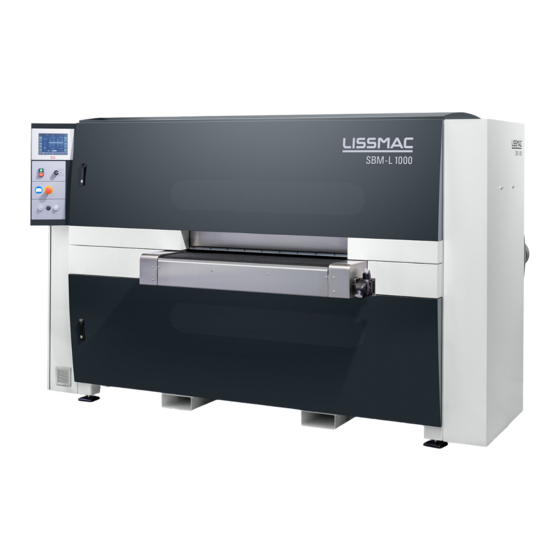
Related Manuals for Lissmac SBM-L 1000 G1S2


Summary of Contents for Lissmac SBM-L 1000 G1S2
- Page 1 METAL PROCESSING OPERATING MANUAL GRINDING MACHINE SBM-L 1000 G1S2 SBM-L 1500 G1S2 LISSMAC Maschinenbau GmbH Lanzstraße 4 D-88410 Bad Wurzach Telephone +49 (0) 7564 / 307 - 0 Telefax +49 (0) 7564 / 307 - 500 lissmac@lissmac.com www.lissmac.com...
-
Page 3: Imprint
Imprint Imprint Operating manual for Grinding Machine SBM-L 1000 G1S2 SBM-L 1500 G1S2 with Siemens S7 control Issue date: 02-2019 Translation of the original operating manual Manufacturer: LISSMAC Maschinenbau GmbH Lanzstraße 4 D-88410 Bad Wurzach Telephone: +49 (0) 7564 / 307 - 0... -
Page 4: Table Of Contents
Table of Contents Table of Contents Imprint ............................3 Table of Contents ........................4 About this manual ......................7 Target group ........................ 7 Additional documents ....................7 Presentation of warnings .................... 8 Additional representations ..................8 Safety ..........................9 Safety instructions ...................... 9 Organisational measures .................... - Page 5 Table of Contents 5.2.1 Setup function with key switch ..............30 Operation using display functions ................31 5.3.1 Overview (main screen) ................31 5.3.2 Start screen ....................32 5.3.3 Setting sheet thickness ................34 5.3.4 Setting grinding unit G ................35 5.3.5 Setting grinding unit S ................
- Page 6 Table of Contents 7.1.2 Removing grinding belt drive poly-V belt ..........61 7.1.3 Putting on the poly-V belt ................62 7.1.4 Tensioning the poly-V belts ............... 63 7.1.5 Replacing sliding block drive toothed belt ..........64 Replacing S-unit drive belts ..................65 7.2.1 Remove support bar ...................
-
Page 7: About This Manual
About this manual 1 About this manual Target group The operating manual is directed at the machine operator and the operating and maintenance personnel. This operating manual contains important information on how to operate the machine safely, properly and economically. Each person responsible for operating and maintenance work on the machine must have read and understood this operating manual. -
Page 8: Presentation Of Warnings
About this manual Presentation of warnings In this operating manual warnings are presented according to the following examples: SIGNAL WORD! Type and source of danger Consequences of non-compliance Actions to avert the danger. The signal word next to the danger symbol indicates the degree of danger. This signal word signifies an extremely dangerous situation. -
Page 9: Safety
Safety 2 Safety Safety instructions The SBM-L 1000/1500 G1S2 grinding machine is constructed according to the state of the art and recognised technical safety rules. However, during its use, danger for persons and property damage can occur. The machine is to be used only for intended use in technically faultless condition and in observance of safety instructions. -
Page 10: Normal Operation
Safety Normal operation Before beginning work become familiar with the operating location and working environment. The work environment includes, for example, work area obstructions and assistance options in case of accidents. Only operate the machine in a safe and functional condition. ... -
Page 11: Safety Instructions For Special Types Of Dangers
Safety Safety instructions for special types of dangers 2.7.1 Electric power Work on the machine's electrical systems may only be carried out by electricians according to the rules of electronics. In case of problems with the electrical power supply, turn the machine off immediately. -
Page 12: Explosion Hazard
Safety 2.7.4 Explosion hazard When machining metals and especially non-ferrous metals, grinding causes dusts that, when mixed with air, can form an explosive atmosphere. 2.7.4.1 Measures for explosion protection The operator/owner is responsible for the operation of the system and the system components –... -
Page 13: Symbols On The Machine
Safety 2.7.5 Symbols on the machine The following symbols are located on the machine and warn of dangers coming from the machine: Symbol Meaning This symbol on both conveyor belts indicates the danger that hands or body parts can be pulled in and sheared off. - Page 14 Safety Notes: SBM-L 1000/1500 G1S2 Grinding Machine...
-
Page 15: Product Description
Product description 3 Product description The SBM-L 1000/1500 G1S2 grinding machine is described below. Appropriate usage The grinding machine SBM-L 1000/1500 G1S2 is intended exclusively for one or both side deburring and edge rounding of punched, laser and fine plasma cut workpieces. This machine may only be operated as an installation with a dedicated and approved extraction system. -
Page 16: Technical Data
Product description Technical data The following specifications apply to the SBM-L-1000/1500 grinding machine. SBM-L 1000 G1S2 SBM-L 1500 G1S2 Dimensions and weight Length approx. 2800 mm 3300 mm of the machine Width (incl. conveyor belt) 1500 mm 1500 mm approx. - Page 17 Product description SBM-L 1000 G1S2 SBM-L 1500 G1S2 Number Hydraulic Unit Drive power 0,37 kW / 44 kW 0,37 kW / 44 kW Motor Speed 2800 1/min 2800 1/min Motor Volatage 400 V / 480V 400 V / 480V Power consumption...
-
Page 18: Type Plate
Product description Type plate Type plate Name of machine Serial number of machine Manufactured year Connection values Weight The type plate is located on the back of the grinding machine. SBM-L 1000/1500 G1S2 Grinding Machine... -
Page 19: Structure Of The Grinding Machine
Product description Structure of the grinding machine Components of the machine, input side (front side of SBM-L 1000/1500 G1S2) Control panel with selection switches Display control element Upper device door Conveyor belt for input of workpieces Safety shut off bar Adjustable machine foot Support for transport with forklift Lower device door... - Page 20 Product description Components of the machine, output side (back of SBM-L1000/1500 G1S2) Upper device door Conveyor belt for output of workpieces Main switch OFF/ON for entire machine "EMERGENCY STOP" switch for immediate shutdown of the entire machine Type plate Ventilation grate on switching cabinet Electrical connection Optional interface Lower device door...
-
Page 21: Machining Units
Product description Machining units Machining unit, top Upper edge rounding unit Grinding belt tensioning lever Conveyor belt for input of workpieces Safety shut off bar Belt roller Locking lever Machining unit, bottom Safety shut off bar Grinding belt tensioning lever Belt roller Lower edge rounding unit Grinding Machine SBM-L 1000/1500 G1S2... -
Page 22: Control Elements
Product description Control elements Control and display elements (front side) Display control and display field Key switch for setup function Automatic Start / Stop EMERGENCY STOP ID-key switch (option) RJ45 interface USB-port SBM-L 1000/1500 G1S2 Grinding Machine... -
Page 23: Function
Product description Function There are two machining units built into the grinding machine each in different designs. The front grinding units (3) and (4) remove slight burrs and splashes on the sheet surface. The rear edge rounding units (1) and (6) are equipped with two sanding belts running in opposite directions. -
Page 24: Safety Equipment
Product description Safety equipment The grinding machine has the following safety equipment: »EMERGENCY STOP« buttons (1) on the front and (6) on the back of the machine for the immediate shutdown of the machine in case of emergency. The »EMERGENCY STOP« buttons must be disengaged again after an emergency stop. ... -
Page 25: Preparation For Use
Preparation for use 4 Preparation for use Transporting the machine For transport of the machine by crane, there are two steel carriers (1) and (2) fastened to the top of the machine with attachment points. To do this, it is necessary to unscrew the top cover, to screw in the two steel carriers and to reattach the top cover. -
Page 26: Storing The Machine
Preparation for use Storing the machine Disconnect the electrical connection to the grinding machine. Thoroughly clean all grinding dust and material residue from the grinding machine. Clean the dust extraction shafts using an industrial vacuum cleaner. Completely grease the grinding machine. ... -
Page 27: Connecting The Machine Electrically
Preparation for use 4.3.2 Connecting the machine electrically DANGER High voltage Death or injury from electric shock. Only to be carried out by a certified electrician: Place the main switch on the back of the machine into the "Off" position. ... -
Page 28: Connecting The Extractor System
The flow speed in the extraction ducts must be at least 20 m/s in order to achieve the best results. The specified volume flow must be complied with. LISSMAC: SBM-L 1000/1500 G1S2 min. 3000 m³/h... -
Page 29: Operation
Operation 5 Operation The central functions of the machine are controlled using control elements on the front of the grinding machine. The display provides information about the current settings and status of the machine. The following list gives an overview of the operating functions and associated displays. 5.1.1 Control elements Control elements... -
Page 30: Operation Using Function Switches
Operation Operation using function switches 5.2.1 Setup function with key switch Setup function Open the key oft the machine door Key switch for setup function Button Acknowledge EMERGENCY OFF Open the machine door (1) Turn and hold key switch (2). ... -
Page 31: Operation Using Display Functions
Operation Operation using display functions 5.3.1 Overview (main screen) Bediener Overview (main screen) The following menu items are available on the start screen: Machine malfunction, Emergency Stop activated and Connection error Displays the current menu User level (Option ID key switch) / Date / Time Selection menu for grinding unit G Selection menu for grinding unit S Constant buttons... -
Page 32: Start Screen
Operation 5.3.2 Start screen Description of images on start screen Main menu Return to start screen of the machine. Pos. 1 Sheet thickness The sheet thickness can be adjusted. Pos.2 Grinding unit G Grinding unit G can be adjusted. Pos. 3 Grinding unit S Grinding unit S (Edge rounding unit) can be adjusted. - Page 33 Operation Error messages “Error messages” button. When pressed, the screen with the error messages is shown. Pos. 8 Acknowledge error With this button, the error messages can be acknowledged after the error has been corrected. Pos. 9 Unit activate / inactive By pressing the button, the G-unit at the top can be activated or deactivated.
-
Page 34: Setting Sheet Thickness
Operation 5.3.3 Setting sheet thickness Menu The following menu items are available on the screen: Sheet thickness actual value Increase sheet thickness in jog mode (+) Decrease sheet thickness in jog mode (-) Sheet thickness target value (after corresponding input) Sheet thickness direct input Numerical value direct input The value can be directly entered via the input on the button. -
Page 35: Setting Grinding Unit G
Operation 5.3.4 Setting grinding unit G Grinding unit G New grinding belts must be set on the retracted grinding unit G according to the wear. In job mode the drive motor will control the grinding unit only as long as the icon (1 and 2) on the screen is pushed. -
Page 36: Setting Grinding Unit S
Operation 5.3.5 Setting grinding unit S grinding unit S New abrasive belts must be set on the retracted grinding unit S according to the wear. In job mode the drive motor will control the grinding unit only as long as the icon (1 and 2) on the screen is pushed. -
Page 37: Settings
Operation 5.3.6 Settings Operating hours The operating hours of the individual assemblies are indicated. Settings Next button Offset values Offset values can only be changed by service Next – button Grinding Machine SBM-L 1000/1500 G1S2... -
Page 38: Cleaningintervall And Material Change
Operation 5.3.7 Cleaningintervall and material change Cleaning interval display Expiring time display for the cleaning interval of the machine yellow: clean the machine red: urgently clean the machine Next – button Display Choice of material Steel/Optional aluminium Steel machining is selected. Cleaning interval indicator steel. -
Page 39: Listing Of Tool Wear
Operation Display choice of material aluminium (option) Aluminium machining is selected. Cleaning interval display adjusts to the cleaning interval of aluminium. (Option) 5.3.8 Listing of tool wear Tool wear compensation (option) Tool wear compensation values (option) In this view, the function of the upper and lower tool wear compensation is graphically displayed. -
Page 40: Language Selection And Dimensions
Operation 5.3.9 Language selection and dimensions Language selection Selection mm / inch Setting the language Next – button Pop-up language selection Press the button to display the popup with the available languages of the HMI. Select the language by pressing the respective button. SBM-L 1000/1500 G1S2 Grinding Machine... -
Page 41: Setting Sheet Thickness
Operation 5.3.10 Setting sheet thickness Before processing, the sheet thickness of the workpieces must be measured and adjusted on the machine. Setting sheet thickness Symbol for the sheet thickness +/ - buttons Direct input NOTE Workpieces remaining in the machine Damage to the machine ... -
Page 42: Starting The Machine
Operation 5.3.11 Starting the machine Before starting the machine, the following conditions must be checked: Acceptance of the workpieces at the output side of the machine is ensured. Contamination such as material residue and dust deposits are removed. ... -
Page 43: Id Key Switch (Option)
The set level is displayed on the switch and in the display (item 3) when selecting the position. User level: No key inserted No operation of the system possible Operator Setter Service Administrator* *LISSMAC reserved ID key colour Possible functions on the machine: Operator Level: System start System stop ... - Page 44 Administrator level *: All functions are unlocked and changing the machine references is also possible. Blue *LISSMAC reserved (Level 4/6/8/9) The display of the ID key switch indicates permissible and selected positions by means of yellow, green and red colours.
-
Page 45: Usb Port / Rj45 Interface On The Outside Of The Control Cabinet
Operation USB port / RJ45 interface on the outside of the control cabinet Universally applicable anywhere, where fast access to interfaces and sockets, such as the USB port on the HMI, is necessary and required. The affected housing (control cabinet) thereby remains closed. -
Page 46: Material Data Memory / Recipe Memory Internally
Other freely writeable input fields for identifying / naming the recipes are available for the machine parameters. The graph below shows the scope of services that the customer or LISSMAC must provide. The HMI (KEB Touch) is included in the grinding / deburring machine and the customer has to lay the Ethernet cable from his network to the HMI. -
Page 47: Interface Machine Data Acquisition For External Evaluation (Option)
Operation Interface machine data acquisition for external evaluation (option) Interface in the form of a Harting connector on the back of the machine mounted on the control cabinet. The following information or operating states in digital form are made available as potential-free contacts at this interface. These signals can also be displayed for the visualization of the different operating conditions additionally in the form of an LED lamp “a”... -
Page 48: Processing Material
Operation Processing material WARNING Explosion or fire hazard When using fire- or explosion-prone cleaners to clean the workpieces, there is a risk of fire or explosion during processing or in the event of unfavorable flying sparks. Do not clean workpieces with fire or explosion-prone cleaners. Processing material Pictogram on the machine Place workpieces onto the conveyor belt as shown. -
Page 49: Changing Abrasives
Changing abrasives 6 Changing abrasives Replacing G units grinding belts 6.1.1 Removing upper and lower G units grinding belt Move the upper and lower G units to change the sanding belts completely to their final positions using the tool change button Changing the grinding belt is shown on the upper G unit. -
Page 50: Putting On Grinding Belts
Changing abrasives 6.1.2 Putting on grinding belts Putting on grinding belts Put on the new grinding belt according to running direction arrows. Tighten the grinding belt with the tensioning lever Pay attention to the running direction of the grinding belt; the running direction is marked with arrows. -
Page 51: Replace The Sliding Blocks
Changing abrasives 6.1.4 Replace the sliding blocks The G units are equipped with a slowly following sliding block belt for stabilizing the grinding belts. The sliding block belt is equipped with exchangeable sliding blocks. Check the sliding blocks at each replacement of the grinding belts and exchange if necessary. -
Page 52: Remove The Sliding Block Belt
Changing abrasives 6.1.5 Remove the sliding block belt The G unit must be moved into its end position for replacing the sliding block belt. (tool change look at 5.3.2) In order to work on the sliding blocks or sliding block belts, the safety plate (1) must first be removed on the respective G unit and replaced after the work is completed. -
Page 53: Placing On And Tensioning The Sliding Block Belt
Changing abrasives 6.1.6 Placing on and tensioning the sliding block belt Tensioning the sliding block belt. Tensioning roller Counter nut Tensioning bolt Screw fasteners Put on the sliding block belt according to running direction arrows. Slide the deflection roller to the maximum end position and fix with the screw fasteners (4) (for tightening torque, see Chapter 8.3). -
Page 54: Replacing S-Unit Abrasive Belt
Changing abrasives Replacing S-unit abrasive belt 6.2.1 Preparing to replace the abrasive belt The abrasive belts on the S-unit differ according to the material to be processed. The abrasive belts have opposite operating directions in both the upper and the lower S-unit. The existing wear must be reset to reuse the abrasive belts. -
Page 55: Access To S Unit
Changing abrasives 6.2.3 Access to S unit To change the sanding belts, the upper and lower S units must be moved to their final Upper S-unit positions via the button Changing the abrasive belt is shown on the upper S unit. Changing the abrasive belt in the Lower S unit lower S unit is identical. -
Page 56: Releasing The Tension On The S-Unit Abrasive Belt
Changing abrasives 6.2.4 Releasing the tension on the S-unit abrasive belt The abrasive belts in the S-units are hydraulically tensioned and actuated via the control unit. To release the tension of the abrasive belts, press the button Belt tension (1) on the operating screen on the side of the S-unit. -
Page 57: Place The Abrasive Belt On The S-Unit
Changing abrasives 6.2.5 Place the abrasive belt on the S-unit Removing the grinding belts Back abrasive belt Front abrasive belt Wear noted on abrasive belt Replace the abrasive belts onto the pulleys according to their labels (S-unit, position, and operating direction). ... -
Page 58: Setting Wear
Changing abrasives 6.2.7 Setting wear Measure new belt according to 6.2.8. When reusing existing abrasive belts, reset the to the noted wear value on the abrasive belt, or measure according to 6.2.8. Setting wear Current position of the upper grinding unit Current wear of the abrasive belt Upper grinding unit S up Upper grinding unit S down... -
Page 59: Measuring Wear
Changing abrasives 6.2.8 Measuring wear After replacing an abrasive belt, always adjust the S-unit so that the wear display is on "Zero". If the upper and lower wear measuring device is on zero, a normal edge rounding should be achieved. If a heavy edge rounding is desired, a deviation can also be made. -
Page 60: Setting Wear Display To "Zero
Changing abrasives 6.2.9 Setting wear display to "zero". Correct the wear values of the S-unit until the wear indicator is set to "zero". Apply the wear query. Under the setup level (Password), the units in the S-unit menu can be zeroed using the buttons (3,4,5,6) in the display. ... -
Page 61: Service/Repair
Service/Repair 7 Service/Repair G-unit drive belt 7.1.1 Grinding belt and sliding block belt drive The grinding and sliding block belts are driven via drive belts. These belts must be inspected at regular intervals (see Service intervals, Chapter 8.1) and if necessary retightened or replaced. -
Page 62: Putting On The Poly-V Belt
Service/Repair 7.1.3 Putting on the poly-V belt Putting on the poly-V belt Poly-V belt Put on new poly-V belt. NOTE To prevent damage to the poly-V belt and to the belt drive, make sure that the poly-V belt lies completely on all belt pulleys. SBM-L 1000/1500 G1S2 Grinding Machine... -
Page 63: Tensioning The Poly-V Belts
Service/Repair 7.1.4 Tensioning the poly-V belts Tensioning the poly-V belts Grinding belt drive tensioning roller Grinding belt drive poly-V belt Belt tensioner grinding belt drive screw fastener Upper belt tensioner counter nut Lower belt tensioner counter nut Slide the tensioning roller (1) with the counter nut (4) until the poly-V belt is pre- tensioned. -
Page 64: Replacing Sliding Block Drive Toothed Belt
Service/Repair 7.1.5 Replacing sliding block drive toothed belt Sliding block drive toothed belt Toothed belt Belt tensioner screw fastener Belt tensioner Check toothed belt (1) for wear, replace if necessary Loosen screw fasteners (2). Pull back belt tensioner (3). ... -
Page 65: Replacing S-Unit Drive Belts
Service/Repair Replacing S-unit drive belts To be able to replace the V-belts on the inner side of the S-units, the abrasive belts must first be removed; see Chapter 6.2. 7.2.1 Remove support bar Remove support bar Support bar Screw fasteners ... -
Page 66: Installing The V-Belt
Service/Repair 7.2.3 Installing the V-belt NOTE Always replace the V-belts in pairs. If V-belts are replaced individually, secure drive is no longer possible. Installing the V-belt Inner V-belt Outer V-belt Place both V-belts (1) and (2) onto the pulley. SBM-L 1000/1500 G1S2 Grinding Machine... -
Page 67: Tensioning The V-Belts
Service/Repair 7.2.4 Tensioning the V-belts Tensioning the V-belts Drive motor screw fasteners Counter nut Counter nut Drive motor V-belt pulley Turn counter nut (3) all the way back. Use counter nut (2) to tension the drive motor V-belt pulley (4) until the V-belt can still be pushed in about 1 cm on its longest segment. -
Page 68: Replacing The V-Belt On The Back Of The S-Unit
Service/Repair 7.2.6 Replacing the V-belt on the back of the S-unit NOTE Always replace the V-belts in pairs. If V-belts are replaced individually, secure drive is no longer possible. Outer V-belt drive motor fastening nuts V-belts Counter nuts Counter nut Tensioning bolt ... -
Page 69: Tensioning The V-Belt On The Back Of The S-Unit
Service/Repair 7.2.7 Tensioning the V-belt on the back of the S-unit Tensioning the V-belts Drive motor Fastening nuts V-belts Counter nut Counter nut Tensioning bolt Put new V-belt (3) into place. Turn counter nut (4) back. Use counter nut (5) to tension the drive motor (1) until the V-belt (3) can still be pushed in about 1 cm on its longest segment. -
Page 70: Lubrication Points/ Hydraulic Oil
Service/Repair Lubrication points/ Hydraulic oil 7.3.1 Left guide shafts lubrication points Left guide shafts lubrication points Upper left lubrication points Lower left lubrication points Lubrication points (1) and (2) according to the service schedule. 7.3.2 Right guide shaft lubrication points Right guide shaft lubrication points Upper right lubrication points Lower right lubrication points... -
Page 71: Lubrication Points Of G Unit Upper Operator Side
Service/Repair 7.3.3 Lubrication points of G unit upper operator side Lubrication points of G unit Grease lubrication point Plugs Move tools with the tool change button to maximum position (See 5.3.2) Remove plugs (2) from the cover guide shafts. ... -
Page 72: Lubricating The S-Unit Belt Flanged Bearing
Service/Repair 7.3.4 Lubricating the S-unit belt Flanged bearing Lubricating the Flanged bearing Lubrication nipple of Flanged bearing Lubricate the lubricating nipple (1). SBM-L 1000/1500 G1S2 Grinding Machine... -
Page 73: Check Hydraulic Oil Level
Service/Repair 7.3.5 Check hydraulic oil level NOTE The hydraulic oil level must always be between the minimum and maximum markings. If the hydraulic oil level is too low, the hydraulic belt tensioner for the S-unit cannot work correctly, and belt tension is not assured. Hydraulic oil level Hydraulic oil container Minimum mark... -
Page 74: Cleaning
Service/Repair Cleaning WARNING Cleaning agents - Risk of fire or explosion When using cleaning agents that may cause a fire or explosion, in the event of unfavorable flying sparks in the machine, a fire may start or even explode. Do not use flammable or explosive cleaning agents ... -
Page 75: Cleaning Interval
Service/Repair Clean both dust collection containers (pos. 1) on the grinding machine, as well as the suction pipes for extraction. Close doors again Grinding dust and material residue must be disposed of in accordance with applicable country-specific law. Cleaning interval NOTE The machine is programmed with an automatic cleaning stop. -
Page 76: Service
Service 8 Service Service intervals The following service work should be performed regularly in the specified intervals. The intervals are shortened corresponding to multiple-shift operation. Service work Interval Clean interior of the machine and catch boxes daily/once per shift (see 7.4) every 8 hrs. -
Page 77: Tightening Torques
Service Tightening torques Tightening torque for standard metric thread All maximum permissible tightening torques listed here apply to threaded connections with ISO 4014 – 4018 hexagon head screws and ISO 4762 hexagon socket head screws, as well as screws with analogous head strength for a friction coefficient of μtot = 0.12. Maximum tightening torque Maximum Ma in Nm Hexagon head screws / hexagon... -
Page 78: Troubleshooting
Service Troubleshooting If the machine is not working or is not working correctly, the following causes may pertain. Error Display/behaviour Cause Solution Turn phases (may only be done Indicator lamp »Phase sequence Phase sequence of the power supply does by an electrician) incorrect«... -
Page 79: Customer Service
Service Customer service If malfunctions occur which cannot be remedied by the customer themselves, contact the following customer service address: LISSMAC Maschinenbau GmbH Lanzstraße 4 D-88410 Bad Wurzach Telephone: +49 (0) 7564 / 307 - 0 Fax: + 49 (0) 7564 / 307 - 500 E-mail: lissmac@lissmac.com... -
Page 80: Taking Out Of Operation And Disposal
Taking out of operation and disposal 9 Taking out of operation and disposal If the machine should be dismantled after the end of its service life, it must be properly disassembled and the individual parts delivered to recycling and disposal. The following parts of the machine contain environmentally hazardous substances: ... -
Page 81: 10 Warranty
Warranty 10 Warranty The warranty for this machine is 12 months. For the following listed wear parts the warranty only applies if the wear is not caused by operation. Feed and drive elements, such as toothed racks, gears, pinions, spindles, spindle nuts, spindle bearing, cables, chains, chain wheels, belts ... -
Page 82: Preface Declaration Of Incorporation
For machining of non- ferrous metals other than steel or stainless steel, or non-ferrous light metals other than aluminum, or for mixed operation with such materials, the extractor solution must always be agreed with LISSMAC... -
Page 83: Declaration Of Incomplete Machine
Technical documentation retained by LISSMAC Maschinenbau GmbH, Lanzstraße 4, D-88410 Bad Wurzach. Description of the The LISSMAC SBM-L series grinding machine is used to round the edges of stamped, machine: laser and fine plasma-cut workpieces and may only be operated in combination with an extractor which is approved according to the relevant EC Directive.
Need help?
Do you have a question about the SBM-L 1000 G1S2 and is the answer not in the manual?
Questions and answers
SBM-L 1000 толщина металла 5мм...при запуске наждачная лента не касается метала, в чем может быть проблема? Есть ли какие то настройки стандартные на эту толщину?